pulley TOYOTA RAV4 2006 Service Repair Manual
[x] Cancel search | Manufacturer: TOYOTA, Model Year: 2006, Model line: RAV4, Model: TOYOTA RAV4 2006Pages: 2000, PDF Size: 45.84 MB
Page 23 of 2000
ENGINE - 2AZ-FE ENGINE
01NEG45Y
RegulatorB
M
IG
RLO
L
Ignition Switch
To Discharge
Wa r n i n g L i g h t
Generator
ECM
281EG13
281EG12
Coil SpringPulley
Helical Coil Type One-way Clutch EG-26
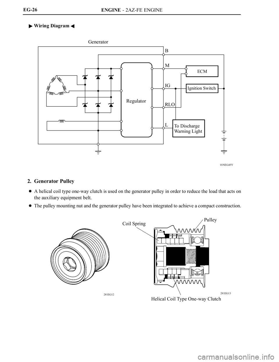
Wiring Diagram
2. Generator Pulley
A helical coil type one-way clutch is used on the generator pulley in order to reduce the load that acts on
the auxiliary equipment belt.
The pulley mounting nut and the generator pulley have been integrated to achieve a compact construction.
Page 26 of 2000
ENGINE - 2AZ-FE ENGINE
240EG98
Idler Pulley for Automatic Tensioner
Generator Pulley
Water Pump Pulley
Air Conditioning
Compressor Pulley Crankshaft Pulley Idler Pulley
258RV77
ArmIdler Pulley
Te n s i o n e r
A - A Cross SectionAAEG-29
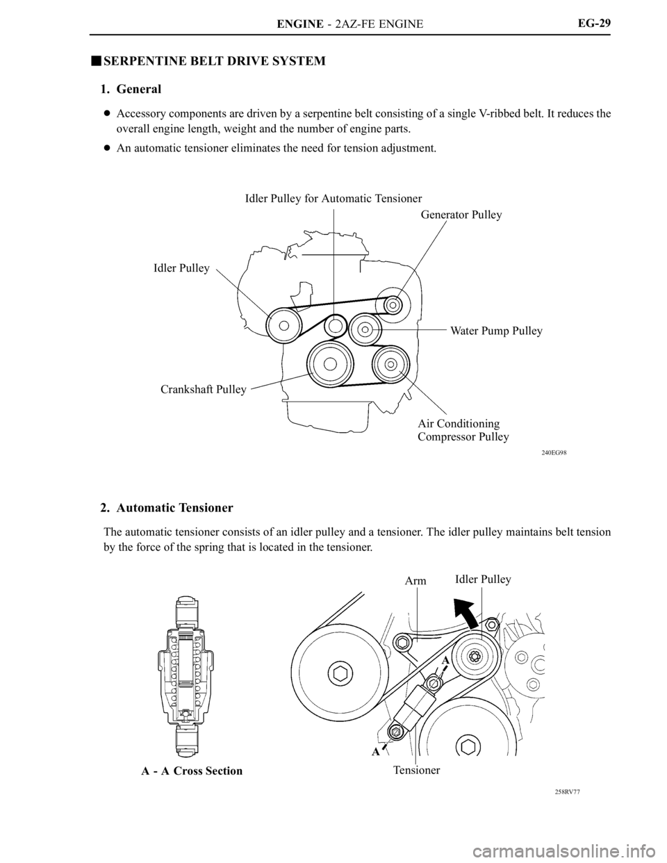
SERPENTINE BELT DRIVE SYSTEM
1. General
Accessory components are driven by a serpentine belt consisting of a single V-ribbed belt. It reduces the
overall engine length, weight and the number of engine parts.
An automatic tensioner eliminates the need for tension adjustment.
2. Automatic Tensioner
The automatic tensioner consists of an idler pulley and a tensioner. The idler pulley maintains belt tension
by the force of the spring that is located in the tensioner.
Page 68 of 2000
ENGINE - 2GR-FE ENGINE EG-72
Item
(1)(2)(3)(4)(5)
ChargingA segment conductor type generator is used.Charging
SystemA generator pulley with a clutch is used.
Starting
SystemThe PS (Planetary reduction-Segment conductor motor)
type starter is used.
Serpentine Belt
Drive SystemA serpentine belt drive system is used.
The MRE (Magnetic Resistance Element) type VVT sensorsThe MRE (Magnetic Resistance Element) type VVT sensors
are used.
The ETCS-i (Electronic Throttle Control System-intelligent)
Engine
The ETCS i (Electronic Throttle Control System intelligent)
is used.
Control
SystemThe ACIS (Acoustic Control Induction System) is used.SystemThe air intake control system is used.
The charging control is used.
Evaporative emission control system is used.
Page 74 of 2000
ENGINE - 2GR-FE ENGINE
285EG81
Plastic Region
Tightening Bolts
Crankshaft
Bearing CapSeal WasherUpper Main Bearing
Oil Grooved
Micro-grooved
Lower Main Bearing
285EG80
Torsional Damper
Rubber EG-78
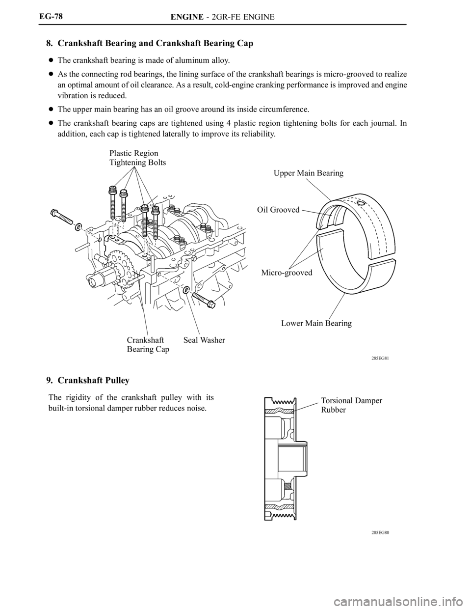
8. Crankshaft Bearing and Crankshaft Bearing Cap
The crankshaft bearing is made of aluminum alloy.
As the connecting rod bearings, the lining surface of the crankshaft bearings is micro-grooved to realize
an optimal amount of oil clearance. As a result, cold-engine cranking performance is improved and engine
vibration is reduced.
The upper main bearing has an oil groove around its inside circumference.
The crankshaft bearing caps are tightened using 4 plastic region tightening bolts for each journal. In
addition, each cap is tightened laterally to improve its reliability.
9. Crankshaft Pulley
The rigidity of the crankshaft pulley with its
built-in torsional damper rubber reduces noise.
Page 95 of 2000

ENGINE - 2GR-FE ENGINE
279EG32
30
A
B
Two Sets of Three-Phase WindingsC
Three-Phase Winding
Vo l t a g e
Staggered 30
A
BRotational
AngleVo l t a g e
C
Rotational
Angle
Dual WindingSingle Winding
281EG13 281EG12
Generator Pulley Cross Section Generator PulleyPulley
Shaft
Coil SpringOne-way ClutchEG-99
2. Dual Winding System (For Towing Package Models and Models with RSES)
A dual winding system is used. This system consists of two sets of three-phase windings whose phases are
staggered 30
. Because the generated waves from the respective windings cancel out each other, magnetic
noise is reduced.
3. Generator Pulley
A one-way clutch is set to the generator pulley. Operation of the one-way clutch cancels generator pulley
inertia and helps to prevent slipping of the V-ribbed belt. This realizes a low tension V-ribbed belt that
achieves reduced friction.
Page 96 of 2000
ENGINE - 2GR-FE ENGINE
01MEG38Y
Water Pump Pulley
Crankshaft Pulley
Air Conditioning
Compressor PulleyIdler Pulley for
Automatic
Te n s i o n e rGenerator Pulley Belt Idler
285EG78
Idler
PulleySpring
Arm
BracketBelt Pulling
Direction
Belt Tension
Direction
Fulcrum
Cross Section EG-98
STARTING SYSTEM
The 2GR-FE engine uses the same starter as the 2AZ-FE engine. For details, see page EG-27.
SERPENTINE BELT DRIVE SYSTEM
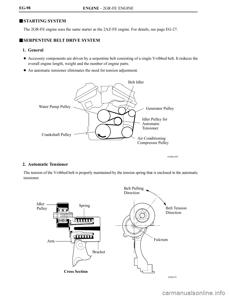
1. General
Accessory components are driven by a serpentine belt consisting of a single V-ribbed belt. It reduces the
overall engine length, weight and the number of engine parts.
An automatic tensioner eliminates the need for tension adjustment.
2. Automatic Tensioner
The tension of the V-ribbed belt is properly maintained by the tension spring that is enclosed in the automatic
tensioner.
Page 203 of 2000
EM–282GR-FE ENGINE MECHANICAL – ENGINE ASSEMBLY
EM
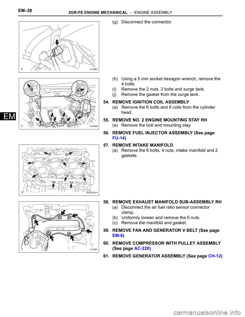
(g) Disconnect the connector.
(h) Using a 5 mm socket hexagon wrench, remove the
4 bolts.
(i) Remove the 2 nuts, 2 bolts and surge tank.
(j) Remove the gasket from the surge tank.
54. REMOVE IGNITION COIL ASSEMBLY
(a) Remove the 6 bolts and 6 coils from the cylinder
head.
55. REMOVE NO. 2 ENGINE MOUNTING STAY RH
(a) Remove the bolt and mounting stay.
56. REMOVE FUEL INJECTOR ASSEMBLY (See page
FU-14)
57. REMOVE INTAKE MANIFOLD
(a) Remove the 6 bolts, 4 nuts, intake manifold and 2
gaskets.
58. REMOVE EXHAUST MANIFOLD SUB-ASSEMBLY RH
(a) Disconnect the air fuel ratio sensor connector
clamp.
(b) Uniformly loosen and remove the 6 nuts.
(c) Remove the manifold and gasket.
59. REMOVE FAN AND GENERATOR V BELT (See page
EM-8)
60. REMOVE COMPRESSOR WITH PULLEY ASSEMBLY
(See page AC-220)
61. REMOVE GENERATOR ASSEMBLY (See page CH-12)
A129467
A129468
A076533E01
A139491
Page 204 of 2000
2GR-FE ENGINE MECHANICAL – ENGINE ASSEMBLYEM–29
EM
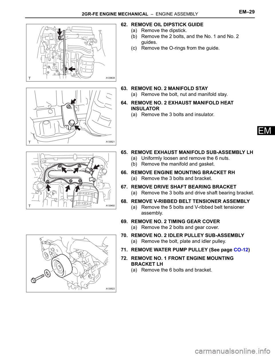
62. REMOVE OIL DIPSTICK GUIDE
(a) Remove the dipstick.
(b) Remove the 2 bolts, and the No. 1 and No. 2
guides.
(c) Remove the O-rings from the guide.
63. REMOVE NO. 2 MANIFOLD STAY
(a) Remove the bolt, nut and manifold stay.
64. REMOVE NO. 2 EXHAUST MANIFOLD HEAT
INSULATOR
(a) Remove the 3 bolts and insulator.
65. REMOVE EXHAUST MANIFOLD SUB-ASSEMBLY LH
(a) Uniformly loosen and remove the 6 nuts.
(b) Remove the manifold and gasket.
66. REMOVE ENGINE MOUNTING BRACKET RH
(a) Remove the 3 bolts and bracket.
67. REMOVE DRIVE SHAFT BEARING BRACKET
(a) Remove the 3 bolts and drive shaft bearing bracket.
68. REMOVE V-RIBBED BELT TENSIONER ASSEMBLY
(a) Remove the 5 bolts and V-ribbed belt tensioner
assembly.
69. REMOVE NO. 2 TIMING GEAR COVER
(a) Remove the 2 bolts and gear cover.
70. REMOVE NO. 2 IDLER PULLEY SUB-ASSEMBLY
(a) Remove the bolt, plate and idler pulley.
71. REMOVE WATER PUMP PULLEY (See page CO-12)
72. REMOVE NO. 1 FRONT ENGINE MOUNTING
BRACKET LH
(a) Remove the 6 bolts and bracket.
A129638
A139521
A139492
A139522
Page 249 of 2000
LU–142GR-FE LUBRICATION – OIL PUMP
LU
(c) Remove the 2 O-rings from the oil pump.
12. REMOVE WATER INLET HOUSING (See page CO-12)
13. REMOVE OIL PIPE (See page EM-52)
14. REMOVE CYLINDER HEAD COVER SUB-ASSEMBLY
(for Bank 1) (See page EM-52)
15. REMOVE NO. 1 OIL PIPE (See page EM-53)
16. REMOVE CYLINDER HEAD COVER SUB-ASSEMBLY
(for Bank 2) (See page EM-53)
17. REMOVE CRANKSHAFT PULLEY (See page EM-54)
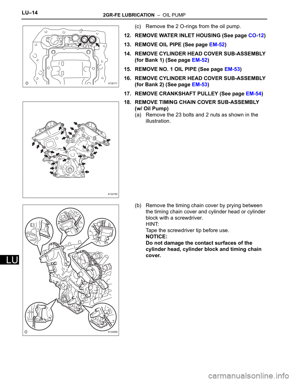
18. REMOVE TIMING CHAIN COVER SUB-ASSEMBLY
(w/ Oil Pump)
(a) Remove the 23 bolts and 2 nuts as shown in the
illustration.
(b) Remove the timing chain cover by prying between
the timing chain cover and cylinder head or cylinder
block with a screwdriver.
HINT:
Tape the screwdriver tip before use.
NOTICE:
Do not damage the contact surfaces of the
cylinder head, cylinder block and timing chain
cover.
A132111
A132150
A132099
Page 340 of 2000
2AZ-FE CHARGING – CHARGING SYSTEMCH–5
CH
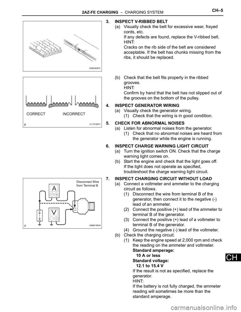
3. INSPECT V-RIBBED BELT
(a) Visually check the belt for excessive wear, frayed
cords, etc.
If any defects are found, replace the V-ribbed belt.
HINT:
Cracks on the rib side of the belt are considered
acceptable. If the belt has chunks missing from the
ribs, it should be replaced.
(b) Check that the belt fits properly in the ribbed
grooves.
HINT:
Confirm by hand that the belt has not slipped out of
the grooves on the bottom of the pulley.
4. INSPECT GENERATOR WIRING
(a) Visually check the generator wiring.
(1) Check that the wiring is in good condition.
5. CHECK FOR ABNORMAL NOISES
(a) Listen for abnormal noises from the generator.
(1) Check that no abnormal noises are heard from
the generator while the engine is running.
6. INSPECT CHARGE WARNING LIGHT CIRCUIT
(a) Turn the ignition switch ON. Check that the charge
warning light comes on.
(b) Start the engine and check that the light goes off.
If the light does not operate as specified,
troubleshoot the charge warning light circuit.
7. INSPECT CHARGING CIRCUIT WITHOUT LOAD
(a) Connect a voltmeter and ammeter to the charging
circuit as follows.
(1) Disconnect the wire from terminal B of the
generator, then connect it to the negative (-)
lead of an ammeter.
(2) Connect the positive (+) lead of the ammeter to
terminal B of the generator.
(3) Connect the positive (+) lead of a voltmeter to
terminal B of the generator.
(4) Ground the negative (-) lead of the voltmeter.
(b) Check the charging circuit.
(1) Keep the engine speed at 2,000 rpm and check
the reading on the ammeter and voltmeter.
Standard amperage:
10 A or less
Standard voltage:
12.1 to 15.4 V
If the result is not as specified, replace the
generator.
HINT:
If the battery is not fully charged, the ammeter
reading will sometimes be more than the
standard amperage.
A095340E01
A111819E01
A088419E04