navigation system TOYOTA RAV4 2020 Owners Manual (in English)
[x] Cancel search | Manufacturer: TOYOTA, Model Year: 2020, Model line: RAV4, Model: TOYOTA RAV4 2020Pages: 736, PDF Size: 30.79 MB
Page 18 of 736
18Pictorial index
When the warning messages are displayed ........................P. 6 3 9
Turn signal lever.............................................. ................... P.202
Headlight switch ............................................... ................. P.209
Headlights/parking lights/tail lights/
license plate lights/daytime running lights .................... ........ P.209
Fog lights
*1............................................................... ............ P.437
Windshield wiper and washer switch............................... P.215
Rear window wiper and washer switch ........................... P.218
Usage.......................................................... ................. P.215, 218
Adding washer fluid .............................................................. P.580
Warning messages ............................................... ............... P.639
Emergency flasher switch ....................................... .......... P.618
Hood lock release lever ........................................ ............. P.571
Tilt and telescopic steering lock release lever ................P. 1 4 2
Adjustment ..................................................... ...................... P.142
Air conditioning system ............................. ............... P.510, 515
Usage.......................................................... ................. P.510, 515
Rear window defogger ........................................... ...... P.511, 517
Audio
*1............................................................... ................. P.375
Audio Plus
*1, 2
Premium Audio*1, 2
Fuel filler door opener lever .................................. ............ P.221
*1: If equipped
*2: Refer to “NAVIGATION AND MULTIMEDIA SYSTEM OWNER’S MAN-
UAL”.
E
F
G
H
I
J
K
L
Page 20 of 736
20Pictorial index
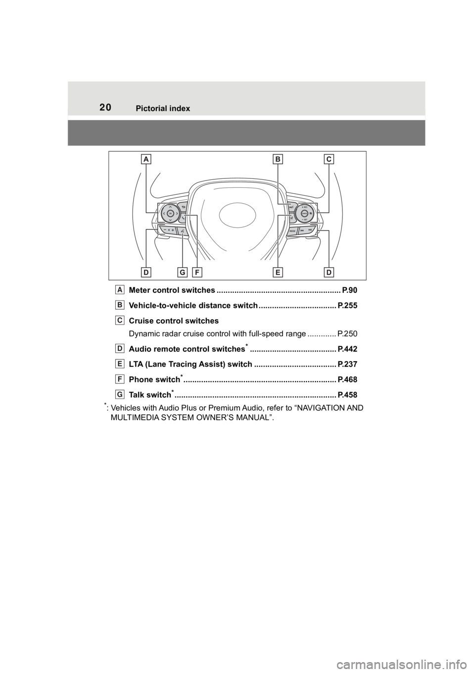
Meter control switches ........................................................ P.90
Vehicle-to-vehicle distance switch ................................... P.255
Cruise control switches
Dynamic radar cruise control with full-speed range ............. P. 2 5 0
Audio remote control switches
*....................................... P.442
LTA (Lane Tracing Assist) switch ............................... ...... P.237
Phone switch
*............................................................... ...... P.468
Talk switch
*............................................................... .......... P.458
*: Vehicles with Audio Plus or Premium Audio, refer to “NAVIGATION AND
MULTIMEDIA SYSTEM OWNER’S MANUAL”.
A
B
C
D
E
F
G
Page 84 of 736
842-1. Instrument cluster
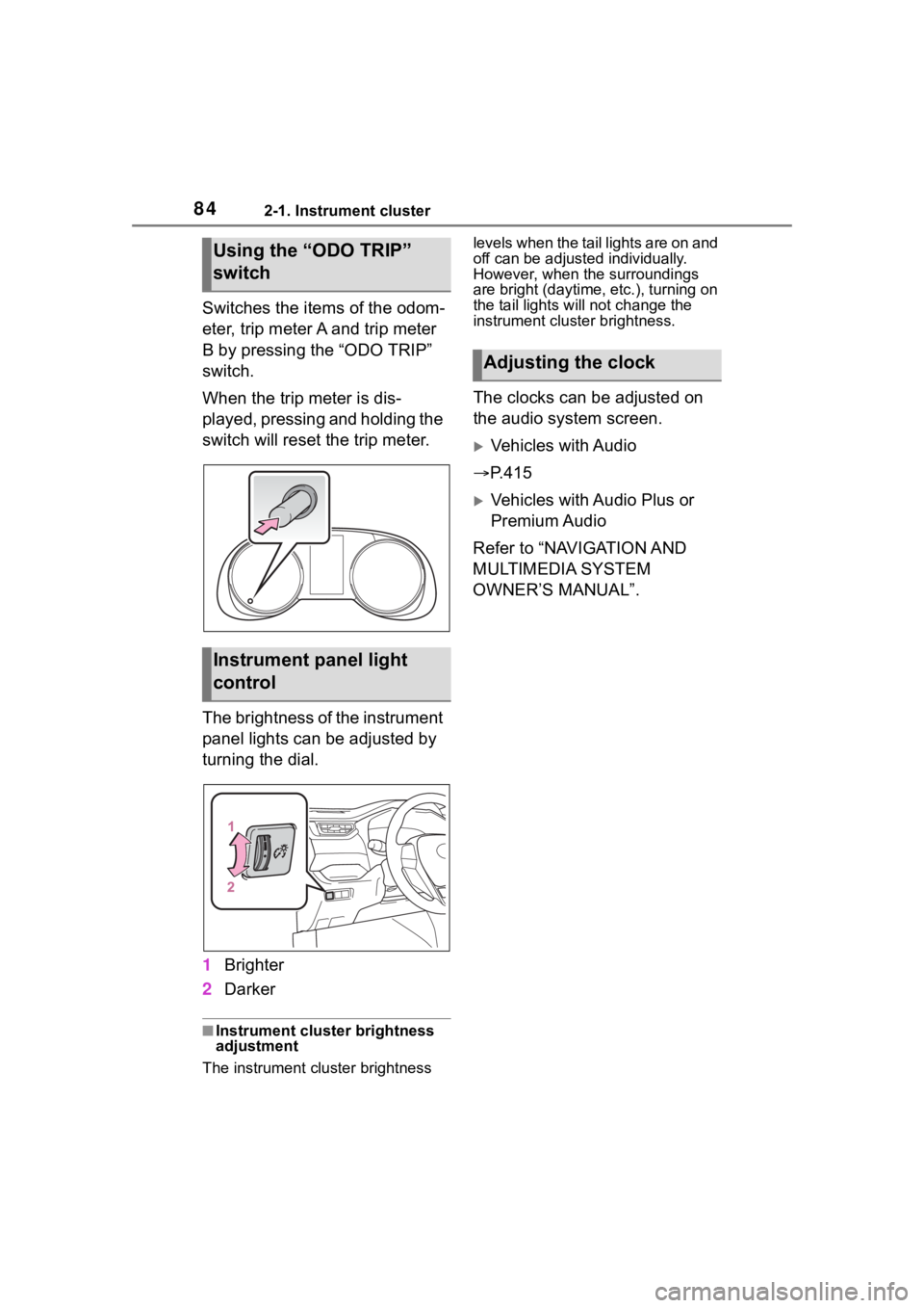
Switches the items of the odom-
eter, trip meter A and trip meter
B by pressing the “ODO TRIP”
switch.
When the trip meter is dis-
played, pressing and holding the
switch will reset the trip meter.
The brightness of the instrument
panel lights can be adjusted by
turning the dial.
1Brighter
2 Darker
■Instrument cluster brightness
adjustment
The instrument cluster brightness levels when the tail lights are on and
off can be adjusted individually.
However, when the surroundings
are bright (daytime, etc.), turning on
the tail lights will not change the
instrument cluster brightness.
The clocks can be adjusted on
the audio system screen.
Vehicles with Audio
P.415
Vehicles with Audio Plus or
Premium Audio
Refer to “NAVIGATION AND
MULTIMEDIA SYSTEM
OWNER’S MANUAL”.
Using the “ODO TRIP”
switch
Instrument panel light
control
Adjusting the clock
Page 88 of 736
882-1. Instrument cluster
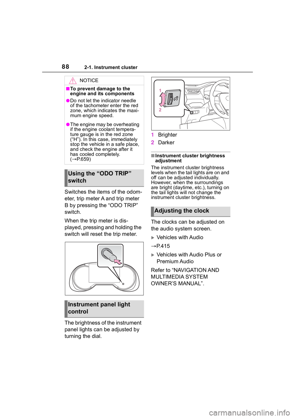
Switches the items of the odom-
eter, trip meter A and trip meter
B by pressing the “ODO TRIP”
switch.
When the trip meter is dis-
played, pressing and holding the
switch will reset the trip meter.
The brightness of the instrument
panel lights can be adjusted by
turning the dial.1
Brighter
2 Darker
■Instrument cluster brightness
adjustment
The instrument cluster brightness
levels when the tail lights are on and
off can be adjusted individually.
However, when the surroundings
are bright (daytime, etc.), turning on
the tail lights will not change the
instrument cluster brightness.
The clocks can be adjusted on
the audio system screen.
Vehicles with Audio
P.415
Vehicles with Audio Plus or
Premium Audio
Refer to “NAVIGATION AND
MULTIMEDIA SYSTEM
OWNER’S MANUAL”.
NOTICE
■To prevent damage to the
engine and its components
●Do not let the i ndicator needle
of the tachomete r enter the red
zone, which indicates the maxi-
mum engine speed.
●The engine may be overheating
if the engine coolant tempera-
ture gauge is in the red zone
(“H”). In this case, immediately
stop the vehicle in a safe place,
and check the engine after it
has cooled completely.
( P.659)
Using the “ODO TRIP”
switch
Instrument panel light
control
Adjusting the clock
Page 90 of 736
902-1. Instrument cluster
■The multi-information display is
displayed when
The engine switch is in ON.
■When changing driving mode
●Background color of the multi-
information display is changed fol-
lowing the select ed driving mode.
( P.351)
●AWD models: Background color of
the multi-informat ion display is
changed following the selected
driving mode or Multi-terrain
Select mode. ( P.351, 353)
■Liquid crystal display
Small spots or light spots may
appear on the display. This phenom-
enon is characteristi c of liquid crys-
tal displays, and there is no problem
continuing to use the display.
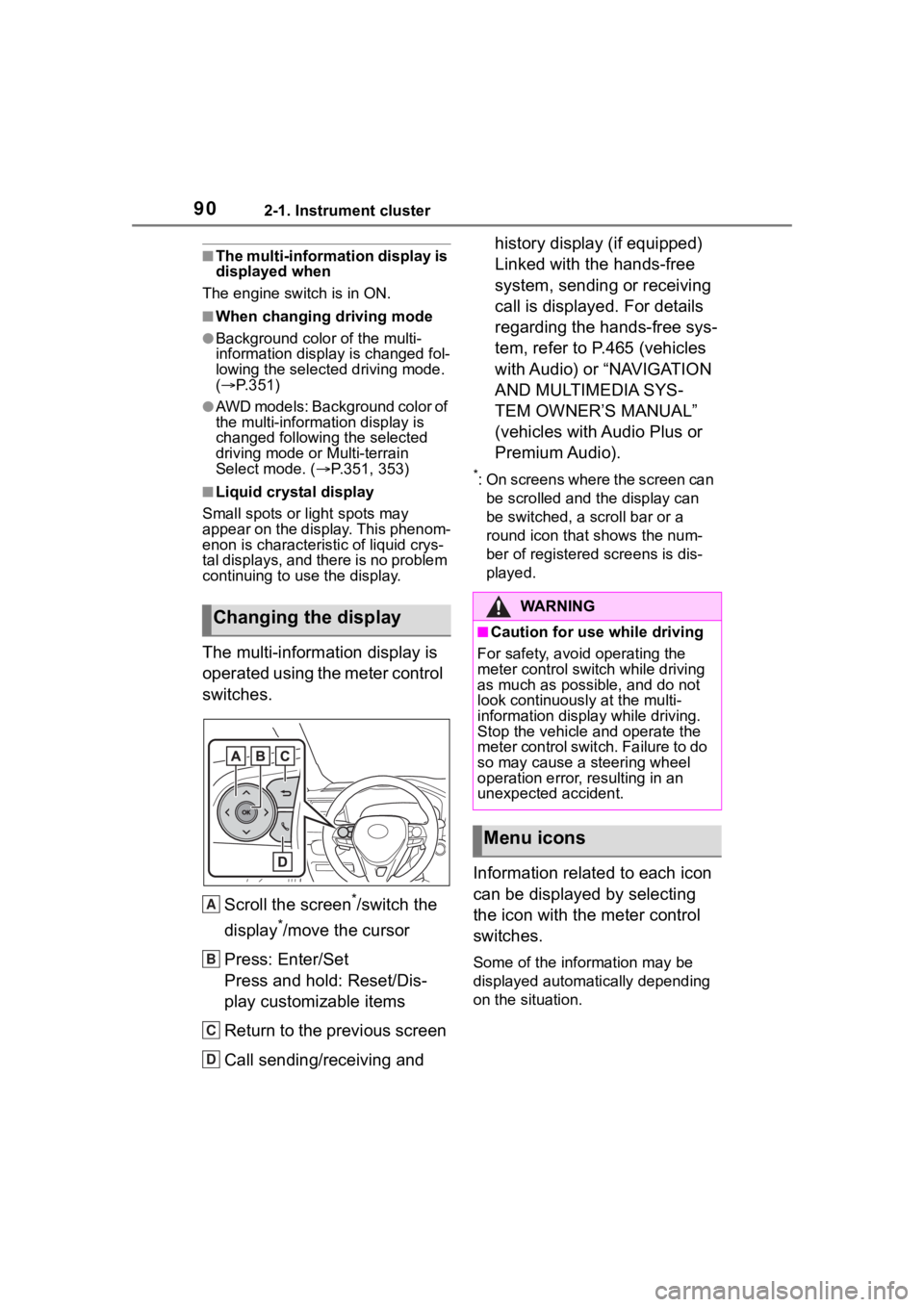
The multi-information display is
operated using the meter control
switches.
Scroll the screen
*/switch the
display
*/move the cursor
Press: Enter/Set
Press and hold: Reset/Dis-
play customizable items
Return to the previous screen
Call sending/receiving and history display (if equipped)
Linked with the hands-free
system, sending or receiving
call is displayed. For details
regarding the hands-free sys-
tem, refer to P.465 (vehicles
with Audio) or “NAVIGATION
AND MULTIMEDIA SYS-
TEM OWNER’S MANUAL”
(vehicles with Audio Plus or
Premium Audio).
*: On screens where the screen can
be scrolled and the display can
be switched, a scroll bar or a
round icon that shows the num-
ber of registered screens is dis-
played.
Information related to each icon
can be displayed by selecting
the icon with the meter control
switches.
Some of the information may be
displayed automatically depending
on the situation.
Changing the display
A
B
C
D
�:�$ �5 �1 �, �1 �*
■Caution for use while driving
For safety, avoid operating the
meter control switch while driving
as much as possible, and do not
look continuously at the multi-
information displa y while driving.
Stop the vehicle and operate the
meter control swit ch. Failure to do
so may cause a steering wheel
operation error, resulting in an
unexpected accident.
Menu icons
Page 93 of 736
932-1. Instrument cluster
2
Vehicle status information and indicators
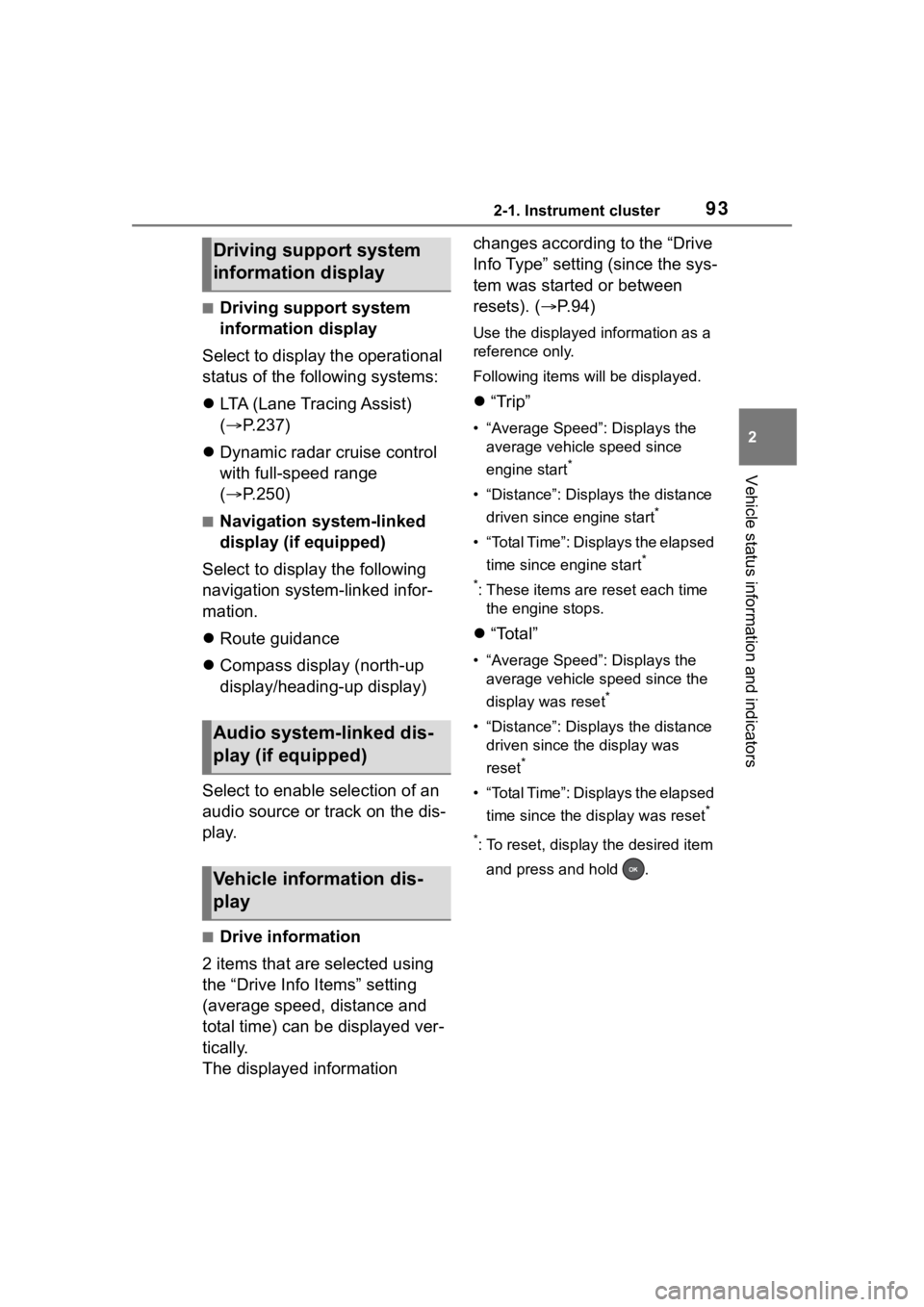
■Driving support system
information display
Select to display the operational
status of the following systems:
LTA (Lane Tracing Assist)
( P.237)
Dynamic radar cruise control
with full-speed range
( P.250)
■Navigation system-linked
display (if equipped)
Select to display the following
navigation system-linked infor-
mation.
Route guidance
Compass display (north-up
display/heading-up display)
Select to enable selection of an
audio source or track on the dis-
play.
■Drive information
2 items that are selected using
the “Drive Info Items” setting
(average speed, distance and
total time) can be displayed ver-
tically.
The displayed information changes according to the “Drive
Info Type” setting (since the sys-
tem was started or between
resets). (
P. 9 4 )
Use the displayed information as a
reference only.
Following items will be displayed.
“Trip”
• “Average Speed”: Displays the
average vehicle speed since
engine start
*
• “Distance”: Displ ays the distance
driven since engine start
*
• “Total Time”: Displays the elapsed time since engine start
*
*
: These items are r eset each time
the engine stops.
“Total”
• “Average Speed”: Displays the
average vehicle speed since the
display was reset
*
• “Distance”: Displ ays the distance
driven since the display was
reset
*
• “Total Time”: Displays the elapsed
time since the display was reset
*
*
: To reset, display the desired item and press and hold .
Driving support system
information display
Audio system-linked dis-
play (if equipped)
Vehicle information dis-
play
Page 97 of 736
972-1. Instrument cluster
2
Vehicle status information and indicators
Select to change the units of mea-
sure displayed.
“Meter Type” (7-inch display)
Select to change the speedometer
display.
(Eco Driving Indicator
Light) ( P.92)
Select to activate/deactivate the
Eco Driving Indicator Light.
(Driving information dis-
play settings)
Select to change the display on
Fuel Economy ( P. 9 1 ) .
(Audio settings) (if
equipped)
Select to enable/disable
screen.
(Vehicle information dis-
play settings)
• “Display Contents”
Select to enable/disable the AWD
system display ( P.94). (AWD
models)
• “Drive Info Type”
Select to change the drive informa-
tion type display between trip and
total. ( P. 9 3 ) .
• “Drive Info Items”
Select to set the items on the upper
and lower side of the drive informa-
tion screen. from three items, aver-
age speed, distance and total time.
“Pop-Up Display”
Select to enable/d isable the follow-
ing pop-up displays, which may
appear in some situations. • Intersection guidance display of
the navigation s ystem-linked sys-
tem (if equipped)
• Incoming call display of the hands-free phone system (if
equipped)
• Audio operation (if equipped)
• Volume operation (if equipped)
• Voice control (if equipped)
• Stop & Start system duration (if equipped)
• Stop & Start system status (if equipped)
“MID OFF”
A blank screen is displayed
“Default Settings”
Select to reset the meter display
settings.
■Suspension of the settings dis-
play
●In the following situations, opera-
tion of the settings display will be
temporarily suspended.
• When a warning message appears on the multi-information
display
• When the vehicle begins to move
●Settings for functions not
equipped to the vehicle are not
displayed.
●When a function is turned off, the
related settings for that function
are not selectable.
Page 247 of 736
2474-5. Using the driving support systems
4
Driving
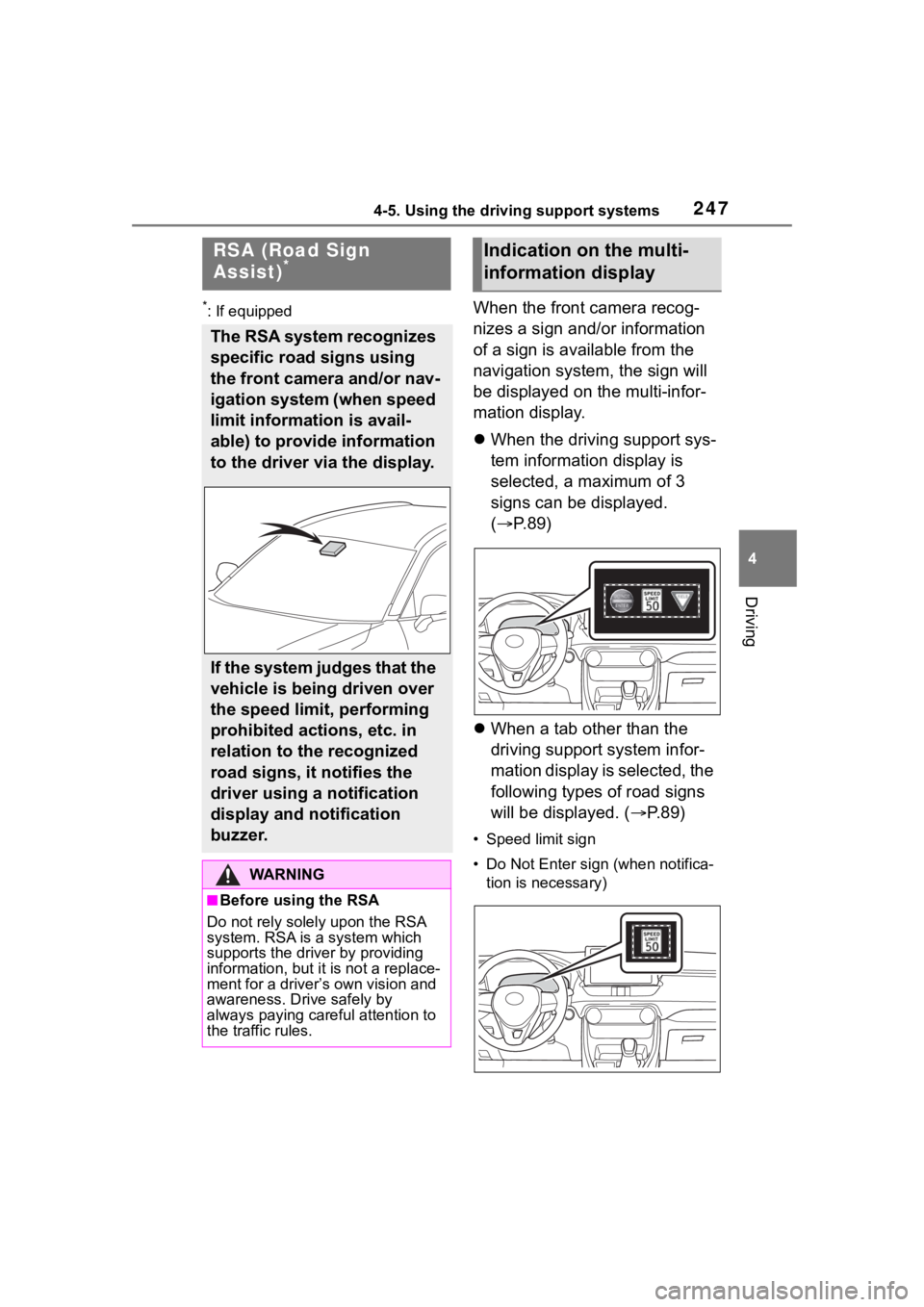
*: If equippedWhen the front camera recog-
nizes a sign and/or information
of a sign is available from the
navigation system, the sign will
be displayed on the multi-infor-
mation display.
When the driving support sys-
tem information display is
selected, a maximum of 3
signs can be displayed.
( P.89)
When a tab other than the
driving support system infor-
mation display is selected, the
following types of road signs
will be displayed. ( P.89)
• Speed limit sign
• Do Not Enter sign (when notifica-
tion is necessary)
RSA (Road Sign
Assist)*
The RSA system recognizes
specific road signs using
the front camera and/or nav-
igation system (when speed
limit information is avail-
able) to provide information
to the driver via the display.
If the system judges that the
vehicle is being driven over
the speed limit, performing
prohibited actions, etc. in
relation to the recognized
road signs, it notifies the
driver using a notification
display and notification
buzzer.
WA R N I N G
■Before using the RSA
Do not rely solely upon the RSA
system. RSA is a system which
supports the driver by providing
information, but it is not a replace-
ment for a driver’s own vision and
awareness. Drive safely by
always paying careful attention to
the traffic rules.
Indication on the multi-
information display
Page 249 of 736
2494-5. Using the driving support systems
4
Driving
heavy rain, fog, snow or sand
storms
●Light from an oncoming vehicle,
the sun, etc. enters the front cam-
era.
●The sign is dirty, faded, tilted or
bent, and if an electronic sign, the
contrast is poor.
●All or part of the sign is hidden by
the leaves of a tree, a pole, etc.
●The sign is only visible to the front
camera for a short amount of time.
●The driving scene (turning, lane
change, etc.) is judged incorrectly.
●Even if it is a sign not appropriate
for the currently traveled lane,
such a sign exists directly after a
freeway branches, or in an adja-
cent lane just before merging.
●Stickers are attached to the rear of
the preceding vehicle.
●A sign resembling a system com-
patible sign is recognized.
●Side road speed signs may be
detected and displayed (if posi-
tioned in sight of the front camera)
while the vehicle is traveling on
the main road.
●Roundabout exit road speed signs
may be detected and displayed (if
positioned in sight of the front
camera) while traveling on a
roundabout.
●The front of the vehicle is raised or
lowered due to the carried load.
●The surrounding brightness is not
sufficient or changes suddenly.
●When a sign intended for trucks,
etc. is recognized.
●The speed information displayed
on the meter and that displayed
on the navigation system may be
different due to the navigation sys-
tem using map data.
■Speed limit sign display
If the engine switch was last turned
off while a speed limit sign was dis- played on the multi-information dis-
play, the same sig
n displays again
when the engine switch is turned to
ON.
■If “RSA Malfunction Visit Your
Dealer” is shown
The system may be malfunctioning.
Have the vehicle inspected by your
Toyota dealer.
■Customization
Some functions can be customized.
(Customizable features: P. 9 4 )
Page 267 of 736
2674-5. Using the driving support systems
4
Driving
■Operation of the RCTA
function
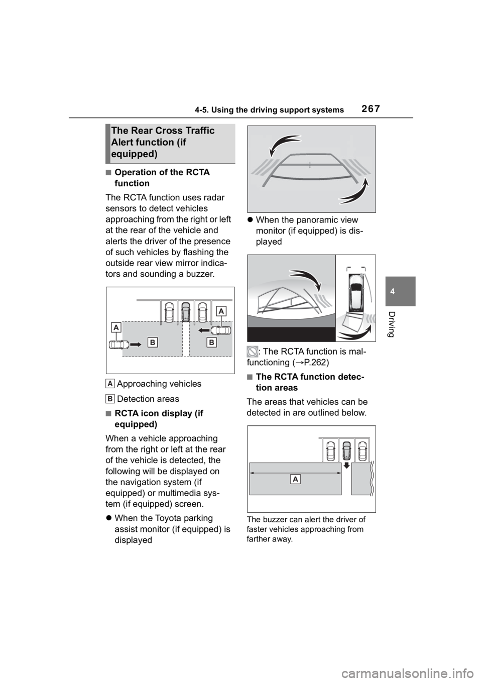
The RCTA function uses radar
sensors to detect vehicles
approaching from the right or left
at the rear of the vehicle and
alerts the driver of the presence
of such vehicles by flashing the
outside rear view mirror indica-
tors and sounding a buzzer.
Approaching vehicles
Detection areas
■RCTA icon display (if
equipped)
When a vehicle approaching
from the right or left at the rear
of the vehicle is detected, the
following will be displayed on
the navigation system (if
equipped) or multimedia sys-
tem (if equipped) screen.
When the Toyota parking
assist monitor (if equipped) is
displayed
When the panoramic view
monitor (if equipped) is dis-
played
: The RCTA function is mal-
functioning ( P.262)
■The RCTA function detec-
tion areas
The areas that vehicles can be
detected in are outlined below.
The buzzer can alert the driver of
faster vehicles approaching from
farther away.
The Rear Cross Traffic
Alert function (if
equipped)
A
B