wheel torque TOYOTA RAV4 2020 Owners Manual (in English)
[x] Cancel search | Manufacturer: TOYOTA, Model Year: 2020, Model line: RAV4, Model: TOYOTA RAV4 2020Pages: 736, PDF Size: 30.79 MB
Page 94 of 736
942-1. Instrument cluster
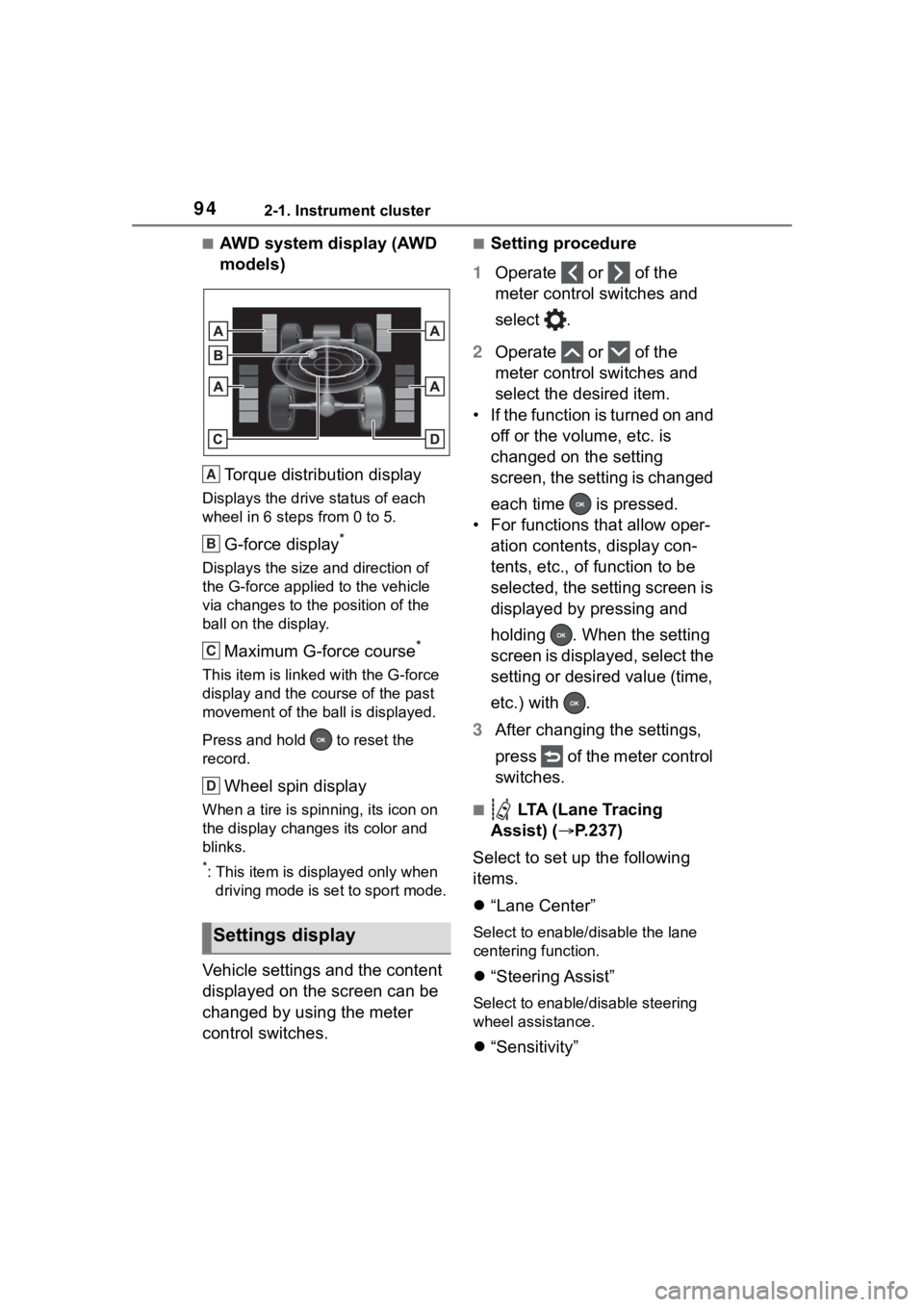
■AWD system display (AWD
models)Torque distribution display
Displays the drive status of each
wheel in 6 steps from 0 to 5.
G-force display*
Displays the size and direction of
the G-force applie d to the vehicle
via changes to the position of the
ball on the display.
Maximum G-force course*
This item is linke d with the G-force
display and the course of the past
movement of the ball is displayed.
Press and hold to reset the
record.
Wheel spin display
When a tire is spin ning, its icon on
the display change s its color and
blinks.
*: This item is displayed only when driving mode is set to sport mode.
Vehicle settings and the content
displayed on the screen can be
changed by using the meter
control switches.
■Setting procedure
1 Operate or of the
meter control switches and
select .
2 Operate or of the
meter control switches and
select the desired item.
• If the function is turned on and off or the volume, etc. is
changed on the setting
screen, the setting is changed
each time is pressed.
• For functions that allow oper- ation contents, display con-
tents, etc., of function to be
selected, the setting screen is
displayed by pressing and
holding . When the setting
screen is displayed, select the
setting or desired value (time,
etc.) with .
3 After changing the settings,
press of the meter control
switches.
■ LTA (Lane Tracing
Assist) ( P.237)
Select to set up the following
items.
“Lane Center”
Select to enable /disable the lane
centering function.
“Steering Assist”
Select to enable/d isable steering
wheel assistance.
“Sensitivity”
Settings display
A
B
C
D
Page 360 of 736
3604-5. Using the driving support systems
■ABS (Anti-lock Brake Sys-
tem)
Helps to prevent wheel lock
when the brakes are applied
suddenly, or if the brakes are
applied while driving on a slip-
pery road surface
■Brake assist
Generates an increased level of
braking force after the brake
pedal is depressed when the
system detects a panic stop sit-
uation
■VSC (Vehicle Stability Con-
trol)
Helps the driver to control skid-
ding when swerving suddenly or
turning on slippery road sur-
faces.
■Enhanced VSC (Enhanced
Vehicle Stability Control)
Provides cooperative control of
the ABS, TRAC, VSC and EPS.
Helps to maintain directional
stability when swerving on slip-
pery road surfaces by con-
trolling steering performance.
■Trailer Sway Control
Helps the driver to control trailer
sway by selectively applying
brake pressure for individual
wheels and reducing driving
torque when trailer sway is
detected.
■TRAC (Traction Control)
Helps to maintain drive power
and prevent the drive wheels
from spinning when starting the
vehicle or accelerating on slip-
pery roads
■Active Cornering Assist
(ACA)
Helps to prevent the vehicle
from drifting to the outer side by
performing inner wheel brake
control when attempting to
accelerate while turning
■Hill-start assist control
Helps to reduce the backward
movement of the vehicle when
starting on an uphill
■EPS (Electric Power Steer-
ing)
Employs an electric motor to
reduce the amount of effort
Driving assist systems
To keep driving safety and
performance, the following
systems operate automati-
cally in response to various
driving situations. Be
aware, however, that these
systems are supplementary
and should not be relied
upon too heavily when oper-
ating the vehicle.
Summary of the driving
assist systems
Page 361 of 736
3614-5. Using the driving support systems
4
Driving
needed to turn the steering
wheel
■Dynamic Torque Control
AWD system (if equipped)
Automatically switches from
front-wheel drive to all-wheel
drive (AWD) according to the
driving conditions, helping to
ensure reliable handling and
stability. Examples of conditions
where the system will switch to
AWD are when cornering, going
uphill, starting off or accelerat-
ing, and when the road surface
is slippery due to snow, rain, etc.
■Dynamic Torque Vectoring
AWD system (if equipped)
Automatically switches from
front wheel drive to all-wheel
drive (AWD) according to the
driving conditions, helping to
ensure reliable handling and
stability. Examples of conditions
where the system will switch to
AWD are when cornering, going
uphill, starting off or accelerat-
ing, and when the road surface
is slippery due to snow, rain, etc.
Also, when the vehicle is corner-
ing, the drive torque distribution
between the front and rear
wheels and between the rear left
and right wheels is precisely
controlled to improve drivability
and stability.
■The Secondary Collision
Brake
When the SRS airbag sensor detects a collision and the sys-
tem operates, the brakes and
brake lights are automatically
controlled to reduce the vehicle
speed and help reduce the pos-
sibility of further damage due to
a secondary collision.
■When the TRAC/VSC/Trailer
Sway Control systems are oper-
ating
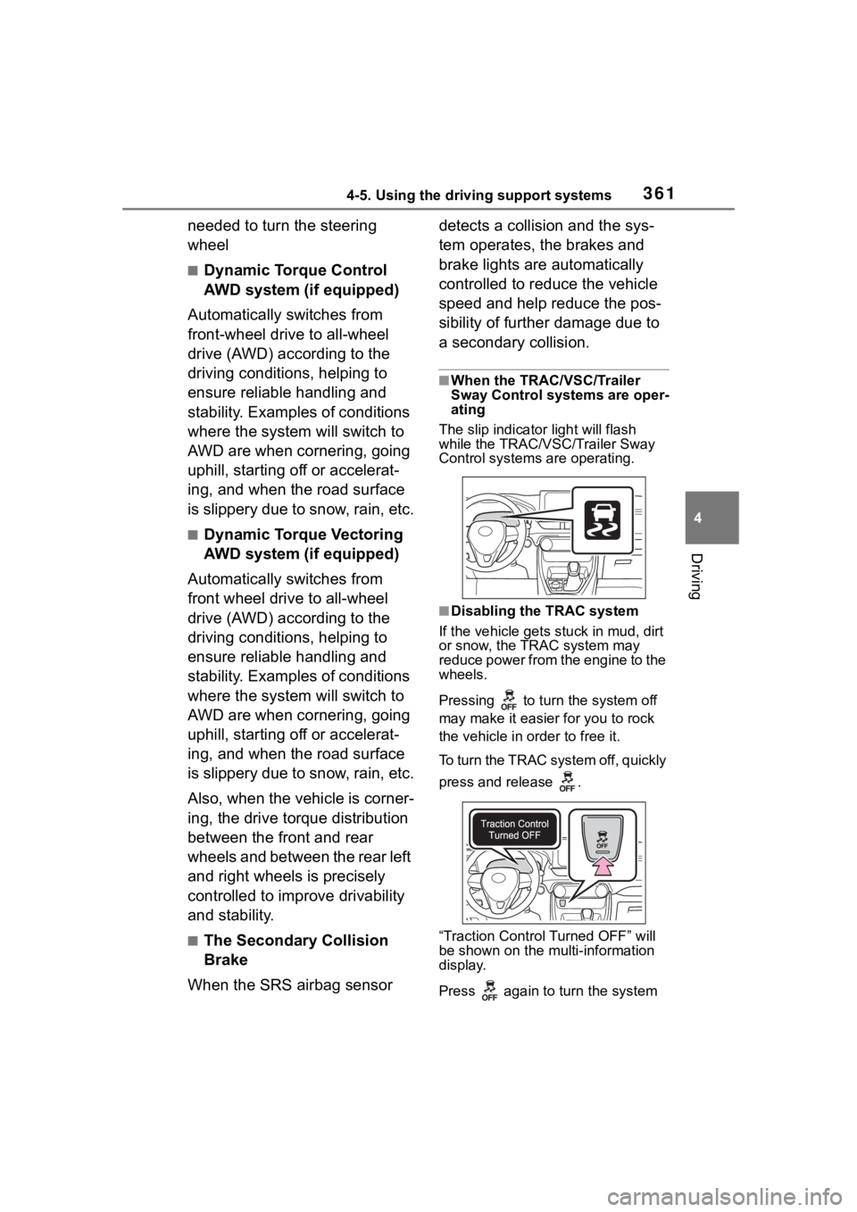
The slip indicator light will flash
while the TRAC/VSC/Trailer Sway
Control systems are operating.
■Disabling the TRAC system
If the vehicle gets stuck in mud, dirt
or snow, the TRAC system may
reduce power from the engine to the
wheels.
Pressing to turn the system off
may make it easier for you to rock
the vehicle in order to free it.
To turn the TRAC system off, quickly
press and release .
“Traction Contro l Turned OFF” will
be shown on the mu lti-information
display.
Press again to turn the system
Page 366 of 736
3664-5. Using the driving support systems
WA R N I N G
■Dynamic Torque Vectoring
AWD system (if equipped)
The cornering performance of the
newly developed AWD system
has been improved. However, do
not overly rely on the system and
drive with caution.
■Replacing tires
Make sure that all tires are of the
specified size, brand, tread pat-
tern and total load capacity. In
addition, make sure that the tires
are inflated to the recommended
tire inflation pressure level.
The ABS, TRAC and VSC/Trailer
Sway Control systems will not
function correctly if different tires
are installed on the vehicle.
Contact your Toyota dealer for fur-
ther information when replacing
tires or wheels.
■Handling of tires and the sus-
pension
Using tires with any kind of prob-
lem or modifying the suspension
will affect the driv ing assist sys-
tems, and may cause a system to
malfunction.
■Trailer Sway Control precau-
tion
The Trailer Sway Control system
is not able to reduce trailer sway
in all situations . Depending on
many factors such as the condi-
tions of the vehicle, trailer, road
surface and driving environment,
the Trailer Sway Control system
may not be effec tive. Refer to
your trailer owner’s manual for
information on how to tow your
trailer properly.
■If trailer sway occurs
Observe the following precau-
tions.
Failing to do so may cause death
or serious injury.
●Firmly grip the steering wheel.
Steer straight ahead. Do not try
to control trailer swaying by
turning the steering wheel.
●Begin releasing the accelerator
pedal immediately but very
gradually to reduce speed.
Do not increase speed. Do not
apply vehicle brakes.
If you make no extreme correction
with the steering or brakes, your
vehicle and traile r should stabi-
lize. ( P.179)
■Secondary Collision Brake
Do not rely sole ly upon the Sec-
ondary Collision Brake. This sys-
tem is designed to help reduce
the possibility of further damage
due to a secondary collision, how-
ever, that effect changes accord-
ing to various conditions. Overly
relying on the system may result
in death or serious injury.
Page 647 of 736
6478-2. Steps to take in an emergency
8
When trouble arises
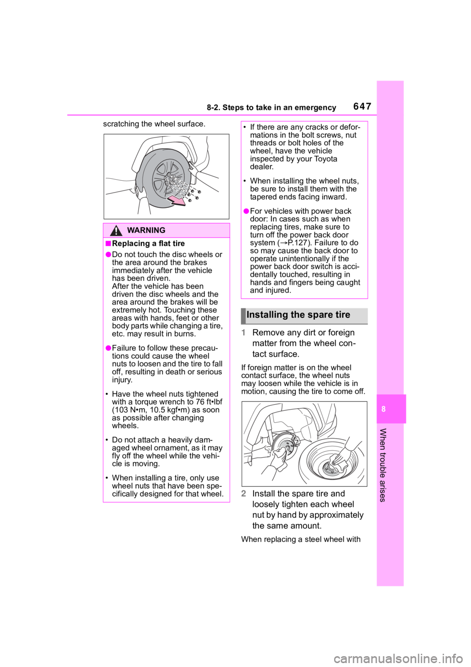
scratching the wheel surface.
1Remove any dirt or foreign
matter from the wheel con-
tact surface.
If foreign matter is on the wheel
contact surface, the wheel nuts
may loosen while the vehicle is in
motion, causing the tire to come off.
2 Install the spare tire and
loosely tighten each wheel
nut by hand by approximately
the same amount.
When replacing a steel wheel with
WA R N I N G
■Replacing a flat tire
●Do not touch the disc wheels or
the area around the brakes
immediately after the vehicle
has been driven.
After the vehicle has been
driven the disc wheels and the
area around the brakes will be
extremely hot. Touching these
areas with hands , feet or other
body parts while changing a tire,
etc. may result in burns.
●Failure to follow these precau-
tions could cause the wheel
nuts to loosen and the tire to fall
off, resulting in death or serious
injury.
• Have the wheel nuts tightened with a torque wrench to 76 ft•lbf
(103 N•m, 10.5 kgf•m) as soon
as possible after changing
wheels.
• Do not attach a heavily dam- aged wheel ornament, as it may
fly off the whee l while the vehi-
cle is moving.
• When installing a tire, only use wheel nuts that have been spe-
cifically designed for that wheel.
• If there are any cracks or defor- mations in the bolt screws, nut
threads or bolt holes of the
wheel, have the vehicle
inspected by your Toyota
dealer.
• When installing the wheel nuts, be sure to install them with the
tapered ends facing inward.
●For vehicles with power back
door: In cases such as when
replacing tires, make sure to
turn off the po wer back door
system ( P.127). Failure to do
so may cause the back door to
operate unintentionally if the
power back door switch is acci-
dentally touched, resulting in
hands and fingers being caught
and injured.
Installing the spare tire
Page 648 of 736
6488-2. Steps to take in an emergency
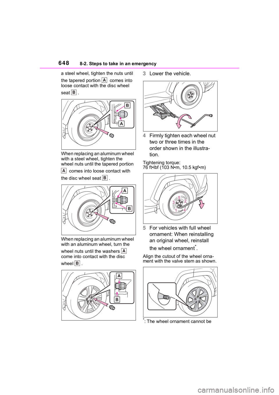
a steel wheel, tight en the nuts until
the tapered portion comes into
loose contact with the disc wheel
seat .
When replacing an aluminum wheel
with a steel wheel, tighten the
wheel nuts until the tapered portion comes into loose contact with
the disc wheel seat .
When replacing an aluminum wheel
with an aluminum wheel, turn the
wheel nuts until the washers
come into contact with the disc
wheel .3 Lower the vehicle.
4 Firmly tighten each wheel nut
two or three times in the
order shown in the illustra-
tion.
Tightening torque:
76 ft•lbf (103 N•m, 10.5 kgf•m)
5For vehicles with full wheel
ornament: When reinstalling
an original wheel, reinstall
the wheel ornament
*.
Align the cutout of the wheel orna-
ment with the valve stem as shown.
*: The wheel ornament cannot be
A
B
A
B
A
B
Page 671 of 736
6719-1. Specifications
9
Vehicle specifications
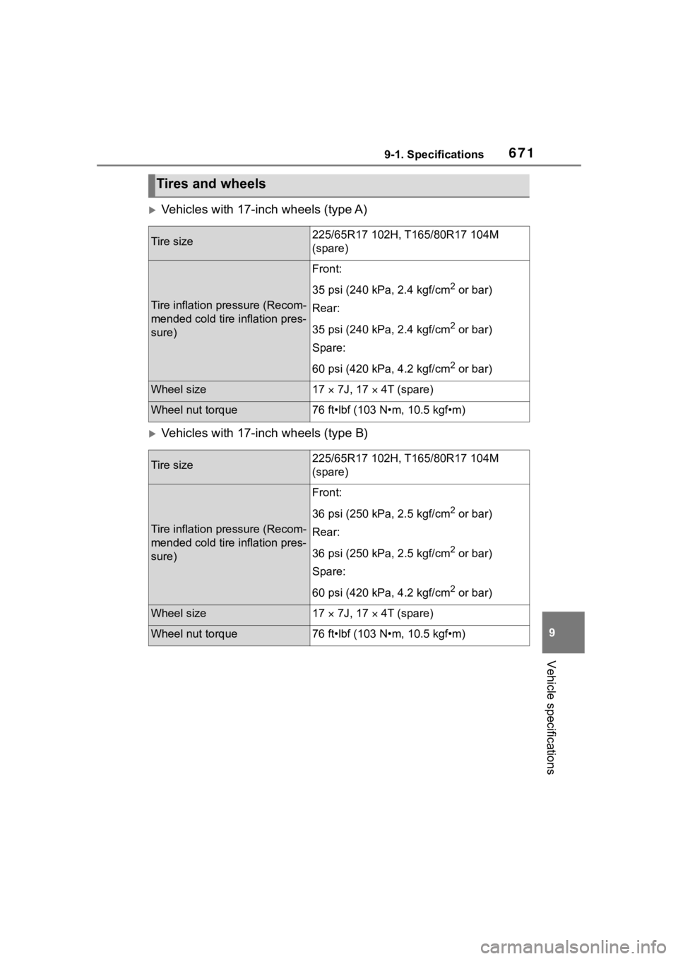
Vehicles with 17-inch wheels (type A)
Vehicles with 17-inch wheels (type B)
Tires and wheels
Tire size225/65R17 102H, T165/80R17 104M
(spare)
Tire inflation pressure (Recom-
mended cold tire inflation pres-
sure)
Front:
35 psi (240 kPa, 2.4 kgf/cm
2 or bar)
Rear:
35 psi (240 kPa, 2.4 kgf/cm
2 or bar)
Spare:
60 psi (420 kPa, 4.2 kgf/cm
2 or bar)
Wheel size17 7J, 17 4T (spare)
Wheel nut torque76 ft•lbf (103 N•m, 10.5 kgf•m)
Tire size225/65R17 102H, T 165/80R17 104M
(spare)
Tire inflation pressure (Recom-
mended cold tire inflation pres-
sure)
Front:
36 psi (250 kPa, 2.5 kgf/cm
2 or bar)
Rear:
36 psi (250 kPa, 2.5 kgf/cm
2 or bar)
Spare:
60 psi (420 kPa, 4.2 kgf/cm
2 or bar)
Wheel size17 7J, 17 4T (spare)
Wheel nut torque76 ft•lbf (103 N•m, 10.5 kgf•m)
Page 672 of 736
6729-1. Specifications
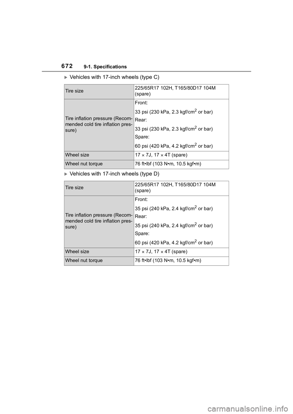
Vehicles with 17-inch wheels (type C)
Vehicles with 17-inch wheels (type D)
Tire size225/65R17 102H, T165/80D17 104M
(spare)
Tire inflation pressure (Recom-
mended cold tire inflation pres-
sure)
Front:
33 psi (230 kPa, 2.3 kgf/cm
2 or bar)
Rear:
33 psi (230 kPa, 2.3 kgf/cm
2 or bar)
Spare:
60 psi (420 kPa, 4.2 kgf/cm
2 or bar)
Wheel size17 7J, 17 4T (spare)
Wheel nut torque76 ft•lbf (103 N•m, 10.5 kgf•m)
Tire size225/65R17 102H, T 165/80D17 104M
(spare)
Tire inflation pressure (Recom-
mended cold tire inflation pres-
sure)
Front:
35 psi (240 kPa, 2.4 kgf/cm
2 or bar)
Rear:
35 psi (240 kPa, 2.4 kgf/cm
2 or bar)
Spare:
60 psi (420 kPa, 4.2 kgf/cm
2 or bar)
Wheel size17 7J, 17 4T (spare)
Wheel nut torque76 ft•lbf (103 N•m, 10.5 kgf•m)
Page 673 of 736
6739-1. Specifications
9
Vehicle specifications
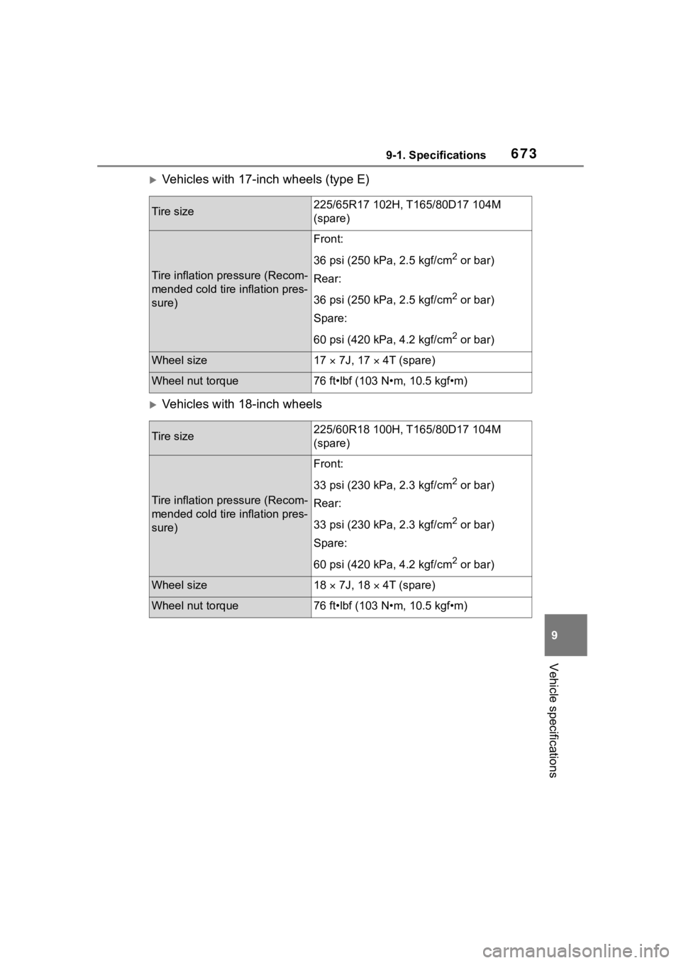
Vehicles with 17-inch wheels (type E)
Vehicles with 18-inch wheels
Tire size225/65R17 102H, T165/80D17 104M
(spare)
Tire inflation pressure (Recom-
mended cold tire inflation pres-
sure)
Front:
36 psi (250 kPa, 2.5 kgf/cm
2 or bar)
Rear:
36 psi (250 kPa, 2.5 kgf/cm
2 or bar)
Spare:
60 psi (420 kPa, 4.2 kgf/cm
2 or bar)
Wheel size17 7J, 17 4T (spare)
Wheel nut torque76 ft•lbf (103 N•m, 10.5 kgf•m)
Tire size225/60R18 100H, T 165/80D17 104M
(spare)
Tire inflation pressure (Recom-
mended cold tire inflation pres-
sure)
Front:
33 psi (230 kPa, 2.3 kgf/cm
2 or bar)
Rear:
33 psi (230 kPa, 2.3 kgf/cm
2 or bar)
Spare:
60 psi (420 kPa, 4.2 kgf/cm
2 or bar)
Wheel size18 7J, 18 4T (spare)
Wheel nut torque76 ft•lbf (103 N•m, 10.5 kgf•m)
Page 674 of 736
6749-1. Specifications
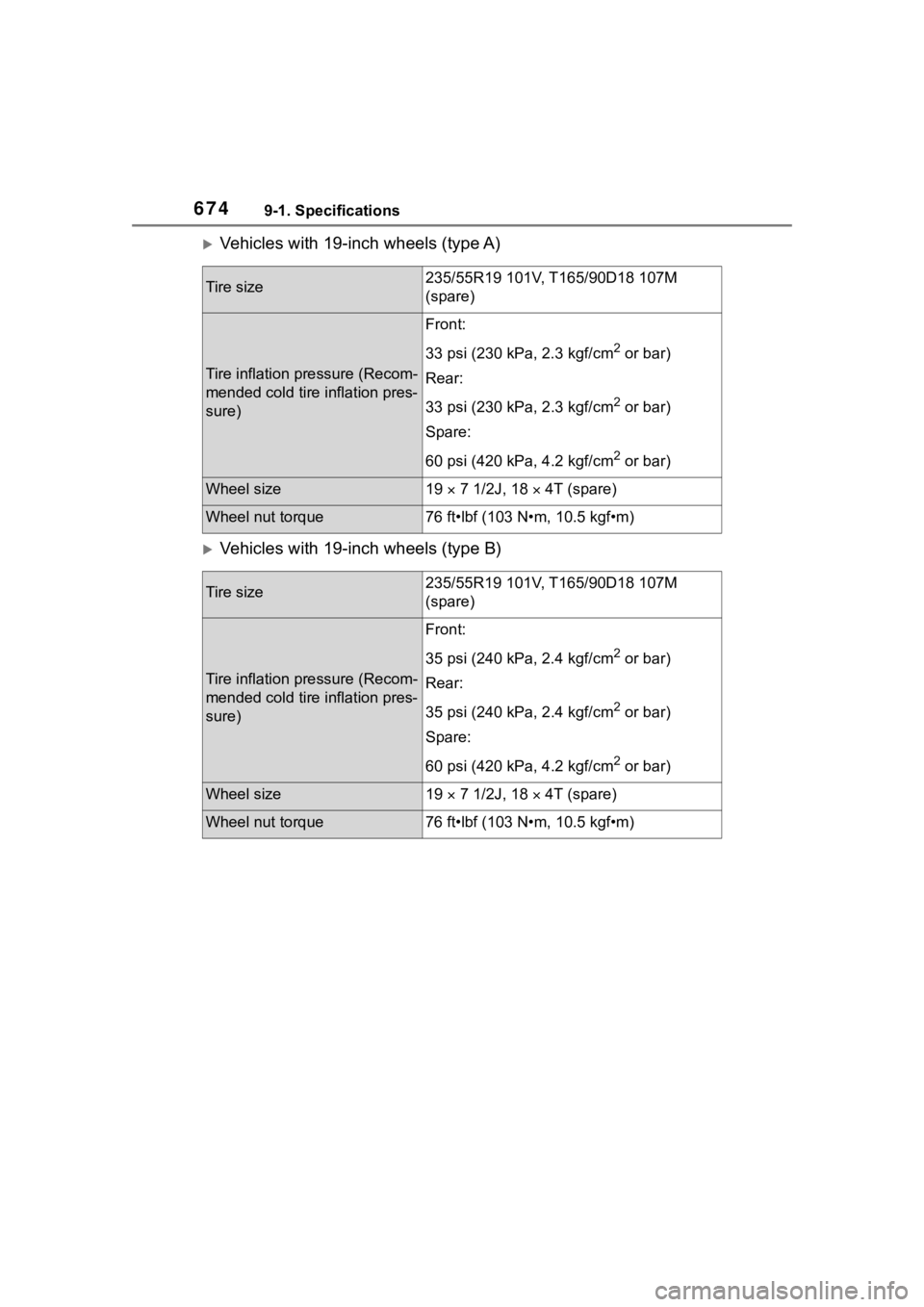
Vehicles with 19-inch wheels (type A)
Vehicles with 19-inch wheels (type B)
Tire size235/55R19 101V, T165/90D18 107M
(spare)
Tire inflation pressure (Recom-
mended cold tire inflation pres-
sure)
Front:
33 psi (230 kPa, 2.3 kgf/cm
2 or bar)
Rear:
33 psi (230 kPa, 2.3 kgf/cm
2 or bar)
Spare:
60 psi (420 kPa, 4.2 kgf/cm
2 or bar)
Wheel size19 7 1/2J, 18 4T (spare)
Wheel nut torque76 ft•lbf (103 N•m, 10.5 kgf•m)
Tire size235/55R19 101V, T165/90D18 107M
(spare)
Tire inflation pressure (Recom-
mended cold tire inflation pres-
sure)
Front:
35 psi (240 kPa, 2.4 kgf/cm
2 or bar)
Rear:
35 psi (240 kPa, 2.4 kgf/cm
2 or bar)
Spare:
60 psi (420 kPa, 4.2 kgf/cm
2 or bar)
Wheel size19 7 1/2J, 18 4T (spare)
Wheel nut torque76 ft•lbf (103 N•m, 10.5 kgf•m)