inflation pressure TOYOTA RAV4 PLUG-IN HYBRID 2021 Owner's Manual
[x] Cancel search | Manufacturer: TOYOTA, Model Year: 2021, Model line: RAV4 PLUG-IN HYBRID, Model: TOYOTA RAV4 PLUG-IN HYBRID 2021Pages: 666, PDF Size: 161.28 MB
Page 579 of 666
577
8
8-2. Steps to take in an emergency
When trouble arises
elapsed, check that the inflation
pressure of each tire is at the speci - fied level and perfo rm initialization.
( →P.523)
■The tire pressure warning light may
come on due to natural causes
The tire pressure w arning light may
come on due to natural causes such as
natural air leaks and tire inflation pres - sure changes caused by temperature. In
this case, adjusting the tire inflation
pressure will turn off the warning light (after a few minutes).
■When a tire is replaced with a com -
pact spare tire (vehicles with com -
pact spare tire)
The compact spare tire is not equipped
with a tire pressure warning valve and
transmitter. If a tire goes flat, the tire pressure warning light will not turn off
even though the flat tire has been
replaced with the spare tire. Replace the spare tire with the standard tire and
adjust the tire inflation pressure. The tire
pressure warning light will go off after a few minutes.
■Conditions that the tire pressure
warning system may not function
properly
→ P.512
WARNING
■If a warning light comes on or a
warning buzzer sounds when a
warning message is shown on
the multi-information display*
Check and follow the message shown
on the multi-information display.
Failure to do so may result in death or serious injury.*: Warning lights illuminate in red or
yellow and the warning buzzer
beeps once or sounds continu -
ously.
■When the electric power steer - ing system warning light comes
on
When the light comes on yellow, the assist to the power steering is
restricted. When the light comes on
red, the assist to the power steering is lost and handling operations of the
steering wheel become extremely
heavy. If the steering wheel becomes heavier
than usual when operating, hold firmly
and operate using more force than usual.
■If the tire pressure warning light comes on
Be sure to observe the following pre -
cautions. Failure to do so could cause a loss of vehicle control and result in
death or serious injury.
●Stop your vehicle in a safe place as soon as possible. Adjust the tire
inflation pressure immediately.
●If the tire pressure warning light
comes on even after tire inflation
pressure adjustment, it is probable that you have a flat tire. Check the
tires. If a tire is flat, change it with
the spare tire and have the flat tire repaired by the nearest authorized
Toyota retailer or Toyota authorized
repairer, or any reliable repairer.
●Avoid abrupt maneuvering and
braking. If the ve hicle tires deterio- rate, you could lo se control of the
steering wheel or the brakes.
■If a blowout or sudden air leak -
age should occur
The tire pressure warning system
may not activate immediately.
Page 589 of 666
587
8
8-2. Steps to take in an emergency
When trouble arises
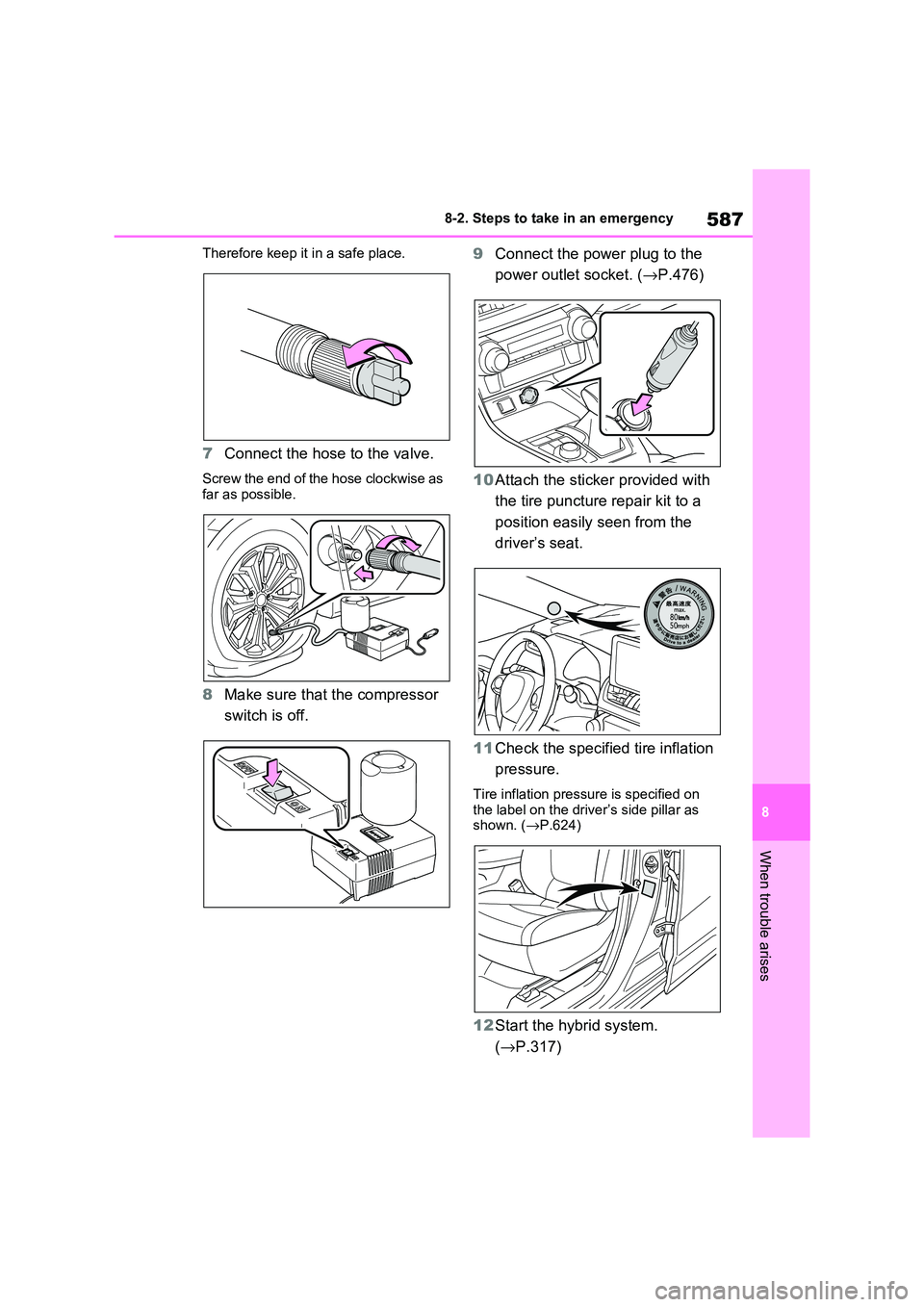
Therefore keep it in a safe place.
7 Connect the hose to the valve.
Screw the end of the hose clockwise as
far as possible.
8 Make sure that the compressor
switch is off.
9 Connect the power plug to the
power outlet socket. ( →P.476)
10 Attach the sticker provided with
the tire puncture repair kit to a
position easily seen from the
driver’s seat.
11 Check the specified tire inflation
pressure.
Tire inflation pressu re is specified on
the label on the driv er’s side pillar as
shown. ( →P.624)
12Start the hybrid system.
( →P.317)
Page 590 of 666
5888-2. Steps to take in an emergency
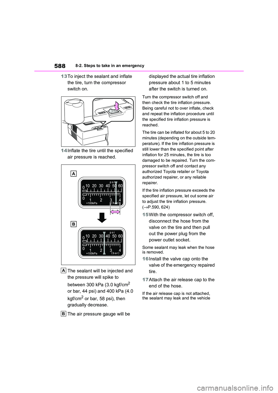
13To inject the sealant and inflate
the tire, turn th e compressor
switch on.
14 Inflate the tire until the specified
air pressure is reached.
The sealant will be injected and
the pressure will spike to
between 300 kPa (3.0 kgf/cm2
or bar, 44 psi) and 400 kPa (4.0
kgf/cm2 or bar, 58 psi), then
gradually decrease.
The air pressure gauge will be
displayed the actual tire inflation
pressure about 1 to 5 minutes
after the switch is turned on.
Turn the compressor switch off and
then check the tire i nflation pressure.
Being careful not to over inflate, check
and repeat the inflat ion procedure until
the specified tire inf lation pressure is
reached.
The tire can be inflated for about 5 to 20
minutes (depending on the outside tem -
perature). If the tire inflation pressure is
still lower than the specified point after
inflation for 25 minutes, the tire is too
damaged to be repaired. Turn the com -
pressor switch off and contact any
authorized Toyota r etailer or Toyota
authorized repairer, or any reliable
repairer.
If the tire inflation pressure exceeds the
specified air pressure, let out some air
to adjust the tire inflation pressure.
( →P.590, 624)
15With the compressor switch off,
disconnect the hose from the
valve on the tire and then pull
out the power plug from the
power outlet socket.
Some sealant may leak when the hose is removed.
16 Install the valve cap onto the
valve of the emergency repaired
tire.
17 Attach the air release cap to the
end of the hose.
If the air release c ap is not attached, the sealant may leak and the vehicle
A
B
Page 591 of 666
589
8
8-2. Steps to take in an emergency
When trouble arises
may get dirty.
18 Temporarily store the bottle in
the luggage compartment while
it is connected to the compres -
sor.
19 To spread the liquid sealant
evenly within the tire, immedi -
ately drive safely for about 5 km
(3 miles) below 80 km/h (50
mph).
20 After driving, stop your vehicle in
a safe place on a hard, flat sur-
face and reconnect the repair
kit.
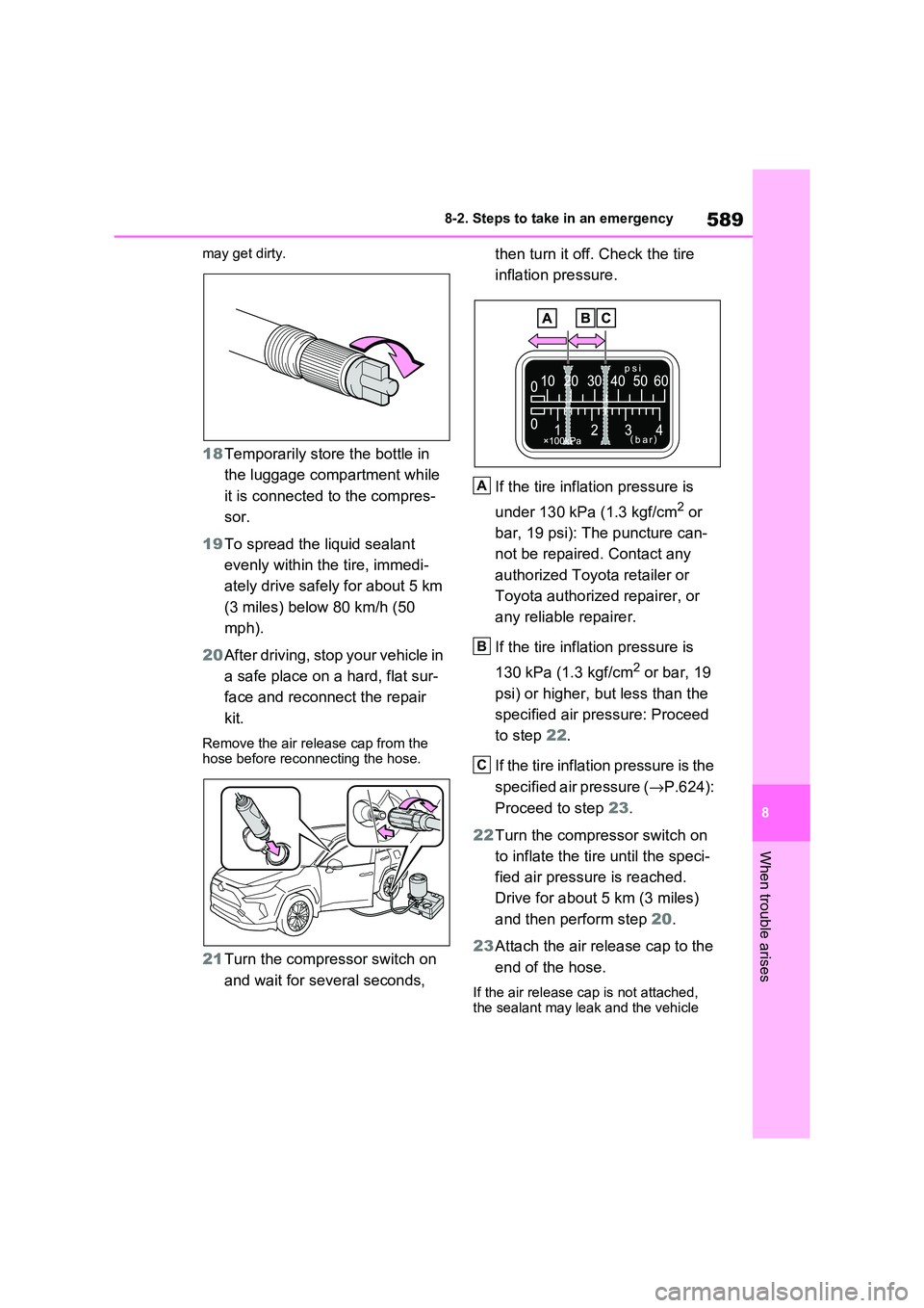
Remove the air rel ease cap from the hose before reconnecting the hose.
21 Turn the compressor switch on
and wait for several seconds,
then turn it off. Check the tire
inflation pressure.
If the tire infla tion pressure is
under 130 kPa (1.3 kgf/cm2 or
bar, 19 psi): The puncture can -
not be repaired . Contact any
authorized Toyota retailer or
Toyota authorized repairer, or
any reliable repairer.
If the tire infla tion pressure is
130 kPa (1.3 kgf/cm2 or bar, 19
psi) or higher, but less than the
specified air pr essure: Proceed
to step 22.
If the tire inflation pressure is the
specified air pressure ( →P.624):
Proceed to step 23.
22 Turn the compressor switch on
to inflate the tire until the speci -
fied air pressure is reached.
Drive for about 5 km (3 miles)
and then perform step 20.
23 Attach the air release cap to the
end of the hose.
If the air release c ap is not attached,
the sealant may leak and the vehicle
A
B
C
Page 592 of 666

5908-2. Steps to take in an emergency
may get dirty.
24 Store the bottle in the luggage
compartment while it is con -
nected to the compressor.
25 Taking precautions to avoid
sudden braking, sudden accel -
eration and sharp turns, drive
carefully at under 80 km/h (50
mph) to the nearest authorized
Toyota retailer or Toyota autho -
rized repairer, or reliable
repairer that is less than 100 km
(62 miles) away for tire repair or
replacement.
For repair and replacement of a tire or
disposal of the tire puncture repair kit, contact any authoriz ed Toyota retailer
or Toyota authorized repairer, or any
reliable repairer.
When having the tire repaired or
replaced, make sure to tell the autho -
rized Toyota retaile r or Toyota autho- rized repairer, or reliable repairer that
the sealant is injected.
■If the tire is inflated to more than
the specified air pressure
1 Disconnect the hose from the valve.
2 Install the air release cap to the end of the hose and push the protrusion
on the air release cap into the tire
valve to let some air out.
3 Disconnect the hose from the valve, remove the air rel ease cap from the
hose and then reconnect the hose.
4 Turn the compressor switch on and
wait for several s econds, and then turn it off. Check that the air pres -
sure indicator shows the specified
air pressure.
If the air pressure is under the desig -
nated pressure, turn the compressor
switch on again and repeat the inflation procedure until the specified air pres-
sure is reached.
■After a tire is re paired with the
emergency tire puncture repair kit
●The tire pressure warning valve and
transmitter should be replaced.
●Even if the tire inflat ion pressure is at
the recommended level, the tire pres - sure warning light may come on/flash.
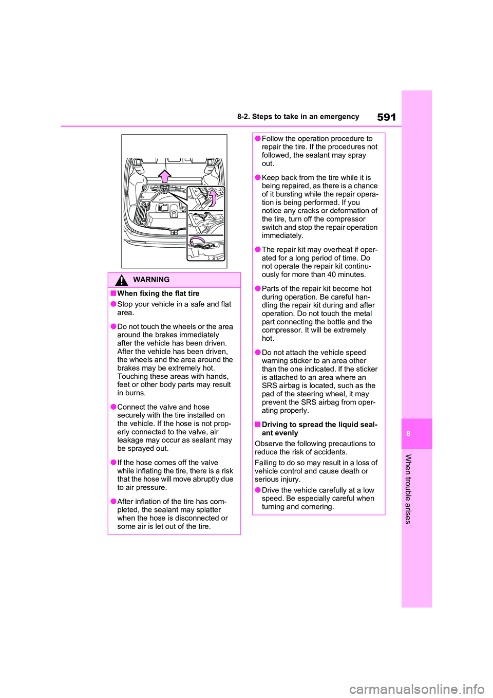
■Taking out the jack (if equipped)
1 Open the deck board.
2 Unhook the tightening strap and take out the jack from the deck under
tray.
After taking out the ja ck, hold it in place by attaching the rubber band temporarily
to the hole shown in the illustration.
To store the jack, rotate the jack and tighten until it no longer moves. Insert it
into the deck under tray and then secure
it in place with a rubber band.
Page 593 of 666
591
8
8-2. Steps to take in an emergency
When trouble arises
WARNING
■When fixing the flat tire
●Stop your vehicle in a safe and flat area.
●Do not touch the wheels or the area
around the brakes immediately after the vehicle has been driven.
After the vehicle has been driven,
the wheels and the area around the brakes may be extremely hot.
Touching these areas with hands,
feet or other body parts may result in burns.
●Connect the valve and hose securely with the tire installed on
the vehicle. If the hose is not prop-
erly connected to the valve, air leakage may occur as sealant may
be sprayed out.
●If the hose comes off the valve
while inflating the tire, there is a risk
that the hose will move abruptly due to air pressure.
●After inflation of the tire has com - pleted, the sealant may splatter
when the hose is disconnected or
some air is let out of the tire.
●Follow the operation procedure to repair the tire. If the procedures not
followed, the seal ant may spray
out.
●Keep back from the tire while it is
being repaired, as there is a chance of it bursting while the repair opera -
tion is being performed. If you
notice any cracks or deformation of the tire, turn off the compressor
switch and stop the repair operation
immediately.
●The repair kit may overheat if oper-
ated for a long period of time. Do not operate the repair kit continu -
ously for more than 40 minutes.
●Parts of the repair kit become hot
during operation. Be careful han -
dling the repair kit during and after operation. Do not touch the metal
part connecting the bottle and the
compressor. It will be extremely hot.
●Do not attach the vehicle speed warning sticker to an area other
than the one indicated. If the sticker
is attached to an area where an SRS airbag is located, such as the
pad of the steering wheel, it may
prevent the SRS airbag from oper - ating properly.
■Driving to spread the liquid seal- ant evenly
Observe the following precautions to
reduce the risk of accidents.
Failing to do so may result in a loss of
vehicle control and cause death or
serious injury.
●Drive the vehicle carefully at a low speed. Be especially careful when
turning and cornering.
Page 594 of 666
5928-2. Steps to take in an emergency
WARNING
●If the vehicle does not drive straight
or you feel a pull through the steer -
ing wheel, stop the vehicle and check the following.
• Tire condition. The tire may have
separated from the wheel.
• Tire inflation pressure. If the tire
inflation pressure is 130 kPa (1.3
kgf/cm2 or bar, 19 psi) or less, the tire may be severely damaged.
NOTICE
■When performing an emergency
repair
●A tire should only be repaired with
the emergency tire puncture repair
kit if the damage is caused by a sharp object such as nail or screw
passing through the tire tread.
Do not remove the sharp object from the tire. Removing the object
may widen the opening and disen -
able emergency repair with the
repair kit.
●The repair kit is not waterproof.
Make sure that the repair kit is not exposed to water, s uch as when it
is being used in the rain.
●Do not put the repa ir kit directly
onto dusty ground such as sand at
the side of the road. If the repair kit vacuums up dust etc., a malfunc -
tion may occur.
●Make sure to stand the kit with the
bottle vertical. The kit cannot work
properly if it is laid on its side.
■Precautions for the emergency
tire puncture repair kit
●The repair kit power source should
be 12 V DC suitable for vehicle use.
Do not connect the repair kit to any other source.
●If fuel splatters on the repair kit, the repair kit may det eriorate. Take
care not to allow fu el to contact it.
●Place the repair kit in a storage to
prevent it from being exposed to dirt
or water.
●Store the repair ki t in the luggage
compartment out of reach of chil - dren.
●Do not disassemble or modify the repair kit. Do not subject parts such
as the air pressure indicator to
impacts. This ma y cause a mal- function.
■To avoid damage to the tire pres - sure warning valves and trans -
mitters
When a tire is repa ired with liquid sealants, the tire pressure warning
valve and transmitter may not operate
properly. If a liquid sealant is used, contact any authorized Toyota retailer
or Toyota authoriz ed repairer, or any
reliable repairer or other qualified ser - vice shop as soon as possible. After
use of liquid sealant, make sure to
replace the tire pressure warning valve and transmitter when repairing
or replacing the tire. ( →P.511)
Page 600 of 666
5988-2. Steps to take in an emergency
If foreign matter is on the wheel contact
surface, the whee l nuts may loosen while the vehicle is in motion, causing
the tire to come off.
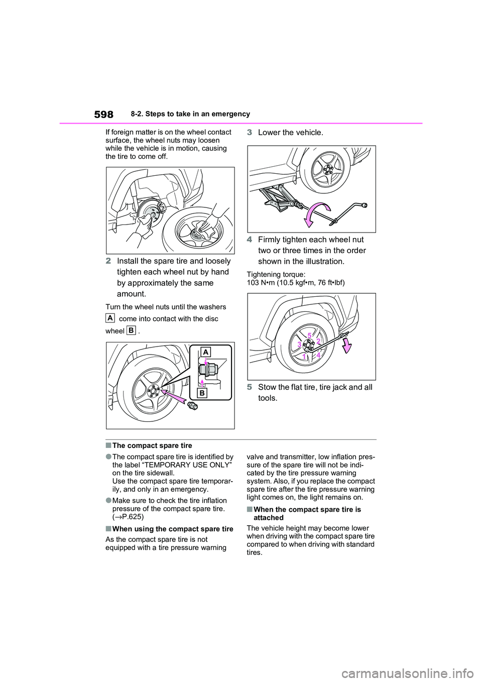
2 Install the spare tire and loosely
tighten each wheel nut by hand
by approximately the same
amount.
Turn the wheel nuts until the washers
come into contact with the disc
wheel .
3 Lower the vehicle.
4 Firmly tighten each wheel nut
two or three times in the order
shown in the illustration.
Tightening torque: 103 N•m (10.5 kgf•m, 76 ft•lbf)
5 Stow the flat tire, tire jack and all
tools.
■The compact spare tire
●The compact spare tire is identified by
the label “TEMPORARY USE ONLY” on the tire sidewall.
Use the compact spar e tire temporar-
ily, and only in an emergency.
●Make sure to check the tire inflation
pressure of the compact spare tire. ( →P.625)
■When using the compact spare tire
As the compact spare tire is not
equipped with a tire pressure warning
valve and transmitter, low inflation pres -
sure of the spare tire will not be indi - cated by the tire pressure warning
system. Also, if you replace the compact
spare tire after the ti re pressure warning light comes on, the light remains on.
■When the compact spare tire is
attached
The vehicle height may become lower when driving with the compact spare tire
compared to when driving with standard
tires.
A
B
Page 627 of 666
625
9
9-1. Specifications
Vehicle specifications
Type B
■Compact spare tire (if equipped)
■When towing a trailer: →P.308
Add 20.0 kPa (0.2 kgf/cm2 or bar, 3 psi) to the recomme nded tire inflation pressure and drive at speeds bel ow 100 km/h (62 mph).
■When all the seats are occupied
Make sure that the rear tires are inflated to 260 kPa (2.6 kgf/cm2 or bar, 38 psi).
Tire inflation pres-
sure (Recom -
mended cold tire
inflation pressure)
Front230 kPa (2.3 kgf/cm2 or bar, 33 psi)
Rear230 kPa (2.3 kgf/cm2 or bar, 33 psi)
Wheel size18 × 7J
Wheel nut torque103 N•m (10.5 kgf•m, 76 ft•lbf)
Tire size235/55R19 101V
Tire inflation pres-
sure (Recom -
mended cold tire
inflation pressure)
Front230 kPa (2.3 kgf/cm2 or bar, 33 psi)
Rear230 kPa (2.3 kgf/cm2 or bar, 33 psi)
Wheel size19 × 7 1/2 J
Wheel nut torque103 N•m (10.5 kgf•m, 76 ft•lbf)
Tire sizeT165/90D18 107M
Tire inflation pressure (Recom-
mended cold tire inflation pres -
sure)
420 kPa (4.2 kgf/cm2 or bar, 60 psi)
Wheel size18 × 4T
Wheel nut torque103 N•m (10.5 kgf•m, 76 ft•lbf)
Page 663 of 666
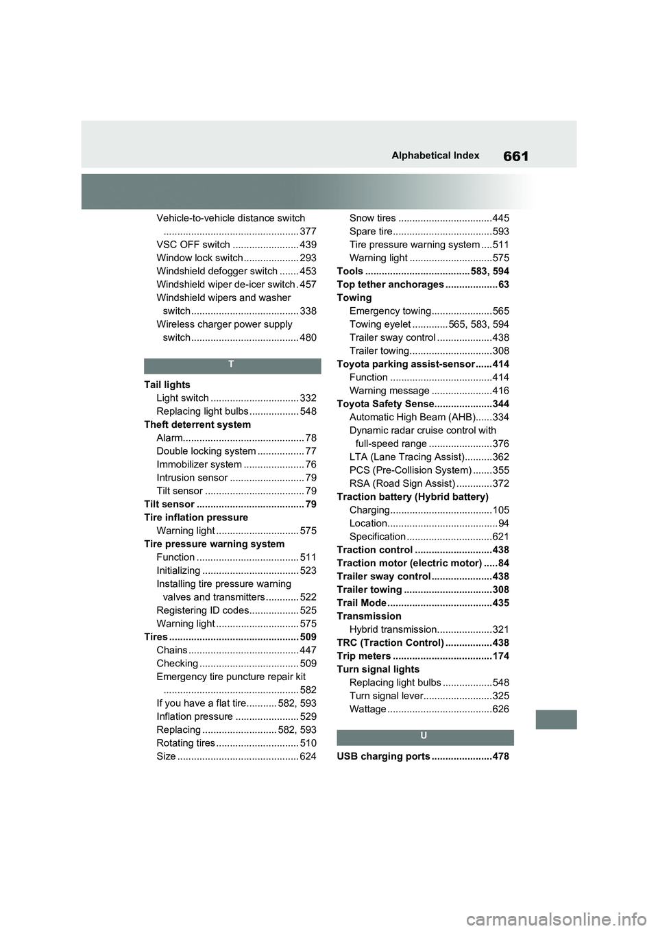
661Alphabetical Index
Vehicle-to-vehicle distance switch
................................................. 377
VSC OFF switch ........................ 439
Window lock switch .................... 293
Windshield defogger switch ....... 453
Windshield wiper de-icer switch . 457
Windshield wipers and washer
switch....................................... 338
Wireless charger power supply
switch....................................... 480
T
Tail lights
Light switch ................................ 332
Replacing light bulbs .................. 548
Theft deterrent system
Alarm............................................ 78
Double locking system ................. 77
Immobilizer system ...................... 76
Intrusion sensor ........................... 79
Tilt sensor .................................... 79
Tilt sensor ....................................... 79
Tire inflation pressure
Warning light .............................. 575
Tire pressure warning system
Function ..................................... 511
Initializing ................................... 523
Installing tire pressure warning
valves and transmitters ............ 522
Registering ID codes.................. 525
Warning light .............................. 575
Tires ............................................... 509
Chains ........................................ 447
Checking .................................... 509
Emergency tire puncture repair kit
................................................. 582
If you have a flat tire........... 582, 593
Inflation pressure ....................... 529
Replacing ........................... 582, 593
Rotating tires ......... ..................... 510
Size ............................................ 624
Snow tires .................................. 445
Spare tire.................................... 593
Tire pressure war ning system ....511
Warning light ..............................575
Tools ......................................583, 594
Top tether anchorages ................... 63
Towing
Emergency towing...................... 565
Towing eyelet .............565, 583, 594
Trailer sway control .................... 438
Trailer towing..............................308
Toyota parking assist-sensor ...... 414
Function .....................................414
Warning message ...................... 416
Toyota Safety Sense.....................344
Automatic High Beam (AHB)...... 334
Dynamic radar cruise control with
full-speed range .......................376
LTA (Lane Tracing Assist)..........362
PCS (Pre-Collision System) .......355
RSA (Road Sign Assist) .............372
Traction battery (Hybrid battery)
Charging.....................................105
Location........................................ 94
Specification ............................... 621
Traction control ............................ 438
Traction motor (elect ric motor) ..... 84
Trailer sway control ...................... 438
Trailer towing ................................308
Trail Mode ......................................435
Transmission
Hybrid transmission.................... 321
TRC (Traction Control) ................. 438
Trip meters .................................... 174
Turn signal lights
Replacing light bulbs ..................548
Turn signal lever......................... 325
Wattage ......................................626
U
USB charging ports ...................... 478