diagram TOYOTA RAV4 PRIME 2023 Owners Manual
[x] Cancel search | Manufacturer: TOYOTA, Model Year: 2023, Model line: RAV4 PRIME, Model: TOYOTA RAV4 PRIME 2023Pages: 662, PDF Size: 25.4 MB
Page 35 of 662

351-1. For safe use
1
For safety and security
Driver airbag
Front passenger occupant classification sensors
Knee airbag
SRS warning light
Airbag sensor assembly
Your vehicle is equipped with ADVANCED AIRBAGS designed
based on the US motor vehicle safety standards (FMVSS208). The
airbag sensor assembly (ECU) cont rols airbag deployment based on
information obtained from the sensors etc. shown in the system
components diagram above. This in formation includes crash sever-
ity and occupant information. As the airbags deploy, a chemical
reaction in the inflators quickly fills the airbags with non-toxic gas to
help restrain the motion of the occupants.
■If the SRS airbags deploy
(inflate)
●Slight abrasions, burns, bruising
etc., may be sustained from SRS
airbags, due to the extremely high
speed deployment (inflation) by
hot gases.
●A loud noise and white powder will
be emitted.
●Parts of the airbag module (steer-
ing wheel hub, airbag cover and
inflator) as well as the front seats,
parts of the front and rear pillars,
and roof side rails, may be hot for
several minutes. T he airbag itself
may also be hot.
●The windshield may crack.
●The hybrid system will be stopped
and fuel supply to the engine will
be stopped. ( P.89)
●All of the doors will be unlocked.
( P.223)
●The brakes and st op lights will be
controlled automatically.
( P.408)
●The interior lights will turn on auto-
matically. ( P.436)
●The emergency flashers will turn
on automatically. ( P.534)
●For Safety Connect subscribers, if
any of the following situations
occur, the system is designed to
send an emergency call to the
response center, notifying them of
the vehicle’s location (without
needing to push the “SOS” button)
and an agent will attempt to speak
with the occupants to ascertain
the level of emergency and assis-
tance required. If the occupants
are unable to communicate, the
agent automatically treats the call
as an emergency and helps to dis-
patch the necessary emergency
services. ( P.65)
• An SRS airbag is deployed.
• A seat belt pretensioner is acti-
vated.
• The vehicle is involved in a severe
rear-end collision.
■SRS airbag deployment condi-
tions (SRS front airbags)
●The SRS front airbags will deploy
in the event of an impact that
exceeds the set threshold level
(the level of forc e corresponding
to an approximately 12 - 18 mph
[20 - 30 km/h] frontal collision with
a fixed wall that does not move or
deform).
However, this threshold velocity will
N
O
P
Q
R
Page 390 of 662

3925-5. Using the driving support systems
parking lots).
●When there is a rut or hole in the
surface of the road.
●When driving on a metal cover
(grating), such as those used for
drainage ditches.
●When driving up or down a steep
slope.
●If a sensor is hit by a large amount
of water, such as when driving on
a flooded road.
●There is dirt, snow, water drops or
ice on a sensor. (Cleaning the
sensors will resolve this problem.)
●A sensor is coated with a sheet of
spray or heavy rain.
●When driving in inclement weather
such as fog, snow or a sandstorm.
●When strong winds are blowing.
●When vehicle horns, vehicle
detectors, motorcycle engines, air
brakes of large vehicles, the clear-
ance sonar of other vehicles or
other devices which produce ultra-
sonic waves are near the vehicle.
●If the front of the vehicle is raised
or lowered due to the carried load.
●If the orientation of a sensor has
been changed due t o a collision or
other impact.
●The vehicle is approaching a tall
or curved curb.
●Driving close to columns (H-
shaped steel beams, etc.) in multi-
story parking garages, construc-
tion sites, etc.
●If the vehicle cannot be driven in a
stable manner, such as when the
vehicle has been in an accident or is malfunctioning.
●On an extremely bumpy road, on
an incline, on gravel, or on grass.
●When tire chains, a compact
spare tire or an emergency tire
puncture repai
r kit are used.
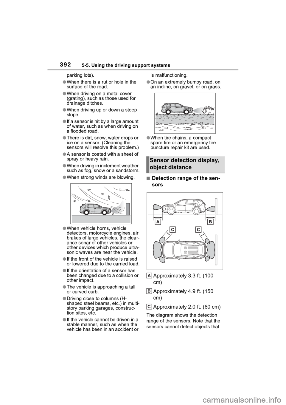
■Detection range of the sen-
sors
Approximately 3.3 ft. (100
cm)
Approximately 4.9 ft. (150
cm)
Approximately 2.0 ft. (60 cm)
The diagram shows the detection
range of the sensors. Note that the
sensors cannot detect objects that
Sensor detection display,
object distance
A
B
C
Page 621 of 662

62310-1. For owners
10
For owners
Contacteur de boucle de ceinture de sécurité du passager avant
Capteurs d’impact latéral (arrière)
Limiteurs de force et dispositifs de tension des ceintures de s écu-
rité (sièges latéraux arrière)
Capteur de position du siège du conducteur
Coussin gonflable du conducteur
Capteurs du système de classif ication de l’occupant du siège du
passager avant
Coussin gonflable de protection des genoux
Lampe témoin SRS
Module de capteur de coussin gonflable
Votre véhicule est doté de COUSSINS GONFLABLES ÉVOLUÉS
dont la conception s’appuie sur les normes de sécurité des véhi cules
à moteur américains (FMVSS208). Le module de capteur de coussin
gonflable (ECU) contrôle le déplo iement des coussins gonflables en
fonction des informations obtenues des capteurs et d’autres élé-
ments affichés dans le diagramme des composants du système ci-
dessus. Ces informations comprennent des données relatives à la
gravité de l’accident et aux occ upants. Au moment du déploiemen t
des coussins gonflables, une réaction chimique se produit dans les
gonfleurs de coussin gonflable et les coussins gonflables se remplis-
sent rapidement d’un gaz non toxique pour aider à limiter le mo uve-
ment des occupants.J
K
L
M
N
O
P
Q
R