brake TOYOTA SIENNA 2007 Service Repair Manual
[x] Cancel search | Manufacturer: TOYOTA, Model Year: 2007, Model line: SIENNA, Model: TOYOTA SIENNA 2007Pages: 3000, PDF Size: 52.26 MB
Page 1805 of 3000
U151F AUTOMATIC TRANSAXLE – AUTOMATIC TRANSAXLE FLUIDAX–123
AX
AUTOMATIC TRANSAXLE FLUID
ON-VEHICLE INSPECTION
1. CHECK FLUID LEVEL
HINT:
Drive the vehicle so that the engine and transaxle are at
normal operating temperature.
Fluid temperature:
70 to 80
C (158 to 176F)
(a) Park the vehicle on a level surface and set the
parking brake.
(b) With the engine idling and the brake pedal
depressed, move the shift lever to all positions from
P to L and return to the P position.
(c) Take out the dipstick and wipe it clean.
(d) Put the dipstick back all the way.
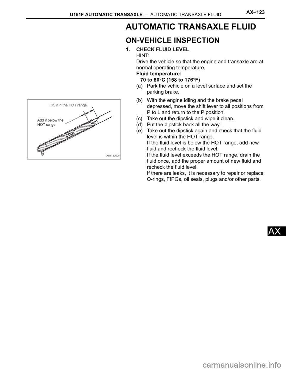
(e) Take out the dipstick again and check that the fluid
level is within the HOT range.
If the fluid level is below the HOT range, add new
fluid and recheck the fluid level.
If the fluid level exceeds the HOT range, drain the
fluid once, add the proper amount of new fluid and
recheck the fluid level.
If there are leaks, it is necessary to repair or replace
O-rings, FIPGs, oil seals, plugs and/or other parts.
D025120E05
Page 1806 of 3000
U151F AUTOMATIC TRANSAXLE – AUTOMATIC TRANSAXLE SYSTEMAX–13
AX
MECHANICAL SYSTEM TESTS
1. PERFORM MECHANICAL SYSTEM TESTS
(a) Measure the stall speed.
The object of this test is to check the overall
performance of the transaxle and engine by
measuring the stall speeds in the D position.
NOTICE:
• Driving test should be done on a paved road
(a nonskid road).
• Perform the test at the normal operating ATF
(Automatic Transmission Fluid) temperature
50 to 80
C (122 to 176F).
• Do not continuously run this test for longer
than 10 seconds.
• To ensure safety, do this test in a wide, clear
level area which provides good traction.
• The stall test should always be carried out in
pairs. One technician should observe the
conditions of wheels or wheel stoppers
outside the vehicle while the other is doing
the test.
(1) Chock the 4 wheels.
(2) Connect the intelligent tester together with the
CAN VIM (controller area network vehicle
interface module) to the DLC3.
(3) Fully apply the parking brake.
(4) Keep your left foot pressed firmly on the brake
pedal.
(5) Start the engine.
(6) Shift into the D position. Press all the way down
on the accelerator pedal with your right foot.
(7) Quickly read the stall speed at this time.
Stall speed:
2,600 +- 150 rpm
Evaluation:
Problem Possible cause
(a) Stall engine speed is low in D position• Engine power output may be insufficient
• Stator one-way clutch not operating properly
HINT:
If the value is less than the specified value by 600 rpm or more, the
torque converter could be faulty.
(b) Stall engine speed is high in D position• Line pressure is too low
• Forward clutch slipping
• U/D (Underdrive) brake slipping
• U/D (Underdrive) one-way clutch is not operating properly
• No.1 one-way clutch not operating properly
• Improper fluid level
Page 1807 of 3000
AX–14U151F AUTOMATIC TRANSAXLE – AUTOMATIC TRANSAXLE SYSTEM
AX
(b) Measure the time lag.
(1) When the shift lever is shifted while the engine is
idling, there will be a certain time lapse or lag
before the shock can be felt. This is used for
checking the condition of the clutch and brake.
NOTICE:
• Perform the test at the normal operating
ATF (Automatic Transmission Fluid)
temperature: 50 to 80
C (122 to 176F).
• Be sure to allow 1 minute interval between
tests.
• Perform the test three times, and measure
the time lags. Calculate the average value
of the three time lags.
• When conducting stall test, do not
continue more than 10 seconds.
(2) Connect the intelligent tester together with the
CAN VIM (controller area network vehicle
interface module) to the DLC3.
(3) Fully apply the parking brake.
(4) Start and warm up the engine and check idle
speed.
Idle speed:
approx. 700 rpm (In N position and A/C
OFF)
(5) Shift the lever from N to D position. Using a stop
watch, measure the time from when the lever is
shifted until the shock is felt.
Time lag:
N
D less than 1.2 seconds
(6) In the same way, measure the time lag for N
R.
Time lag:
N
R less than 1.5 seconds
Evaluation (If N
D or N R time lag is longer than the specified):
Problem Possible cause
N
D time lag is longer• Line pressure is too low
• Forward clutch worn
• No.1 one-way clutch is not operating properly
• U/D (Underdrive) one-way clutch is not operating
• U/D (Underdrive) brake worn
N
R time lag is longer• Line pressure is too low
• Reverse clutch worn
• 1st and reverse brake worn
• U/D (Underdrive) brake worn
Page 1809 of 3000
AX–16U151F AUTOMATIC TRANSAXLE – AUTOMATIC TRANSAXLE SYSTEM
AX
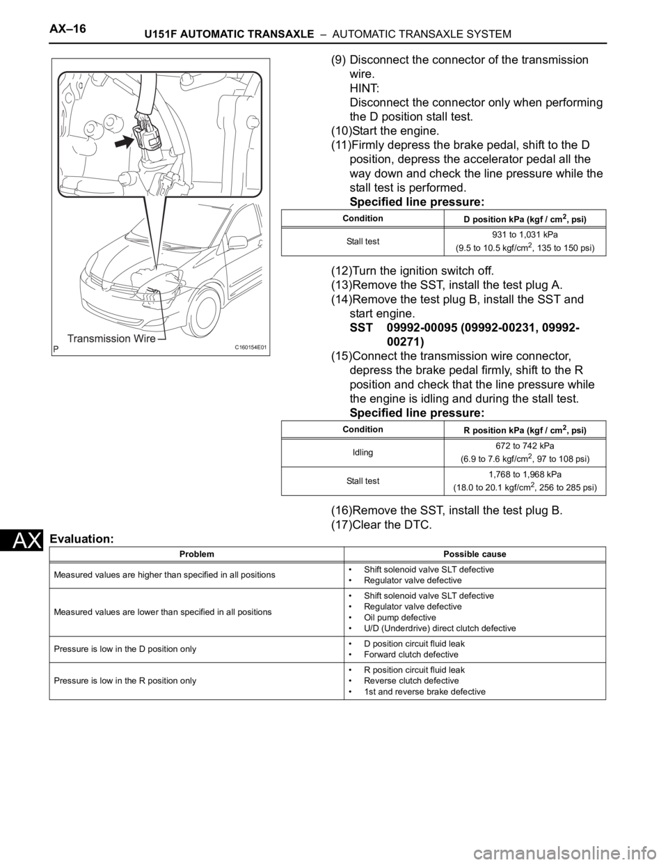
(9) Disconnect the connector of the transmission
wire.
HINT:
Disconnect the connector only when performing
the D position stall test.
(10)Start the engine.
(11)Firmly depress the brake pedal, shift to the D
position, depress the accelerator pedal all the
way down and check the line pressure while the
stall test is performed.
Specified line pressure:
(12)Turn the ignition switch off.
(13)Remove the SST, install the test plug A.
(14)Remove the test plug B, install the SST and
start engine.
SST 09992-00095 (09992-00231, 09992-
00271)
(15)Connect the transmission wire connector,
depress the brake pedal firmly, shift to the R
position and check that the line pressure while
the engine is idling and during the stall test.
Specified line pressure:
(16)Remove the SST, install the test plug B.
(17)Clear the DTC.
Evaluation:
C160154E01
Condition
D position kPa (kgf / cm2, psi)
Stall test931 to 1,031 kPa
(9.5 to 10.5 kgf/cm
2, 135 to 150 psi)
Condition
R position kPa (kgf / cm
2, psi)
Idling672 to 742 kPa
(6.9 to 7.6 kgf/cm
2, 97 to 108 psi)
Stall test1,768 to 1,968 kPa
(18.0 to 20.1 kgf/cm
2, 256 to 285 psi)
Problem Possible cause
Measured values are higher than specified in all positions• Shift solenoid valve SLT defective
• Regulator valve defective
Measured values are lower than specified in all positions• Shift solenoid valve SLT defective
• Regulator valve defective
• Oil pump defective
• U/D (Underdrive) direct clutch defective
Pressure is low in the D position only• D position circuit fluid leak
• Forward clutch defective
Pressure is low in the R position only• R position circuit fluid leak
• Reverse clutch defective
• 1st and reverse brake defective
Page 1810 of 3000
U151F AUTOMATIC TRANSAXLE – PARK / NEUTRAL POSITION SWITCHAX–127
AX
INSPECTION
1. INSPECT PARK/NEUTRAL POSITION SWITCH
ASSEMBLY OPERATION
(a) Apply the parking brake and turn the ignition switch
to the ON position.
(b) Depress the brake pedal and check that the engine
starts only when the shift lever is in the N or P
position and the engine does not start when the shift
lever is in other positions.
(c) Check that the back up light comes on and the
reverse warning buzzer sounds only when the shift
lever is in the R position and the light and buzzer do
not operate when the shift lever is in other positions.
(d) If a failure is found, check the park/neutral position
switch for continuity.
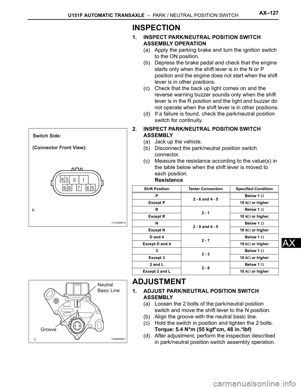
2. INSPECT PARK/NEUTRAL POSITION SWITCH
ASSEMBLY
(a) Jack up the vehicle.
(b) Disconnect the park/neutral position switch
connector.
(c) Measure the resistance according to the value(s) in
the table below when the shift lever is moved to
each position.
Resistance
ADJUSTMENT
1. ADJUST PARK/NEUTRAL POSITION SWITCH
ASSEMBLY
(a) Loosen the 2 bolts of the park/neutral position
switch and move the shift lever to the N position.
(b) Align the groove with the neutral basic line.
(c) Hold the switch in position and tighten the 2 bolts.
Torque: 5.4 N*m (55 kgf*cm, 48 in.*lbf)
(d) After adjustment, perform the inspection described
in park/neutral position switch assembly operation.
C110340E10
Shift Position Tester Connection Specified Condition
P
2 - 6 and 4 - 5Below 1
Except P 10 k or higher
R
2 - 1Below 1
Except R 10 k or higher
N
2 - 9 and 4 - 5Below 1
Except N 10 k or higher
D and 4
2 - 7Below 1
Except D and 4 10 k or higher
3
2 - 3Below 1
Except 3 10 k or higher
2 and L
2 - 8Below 1
Except 2 and L 10 k or higher
C099453E01
Page 1829 of 3000
U151F AUTOMATIC TRANSAXLE – AUTOMATIC TRANSAXLE SYSTEMAX–23
AX
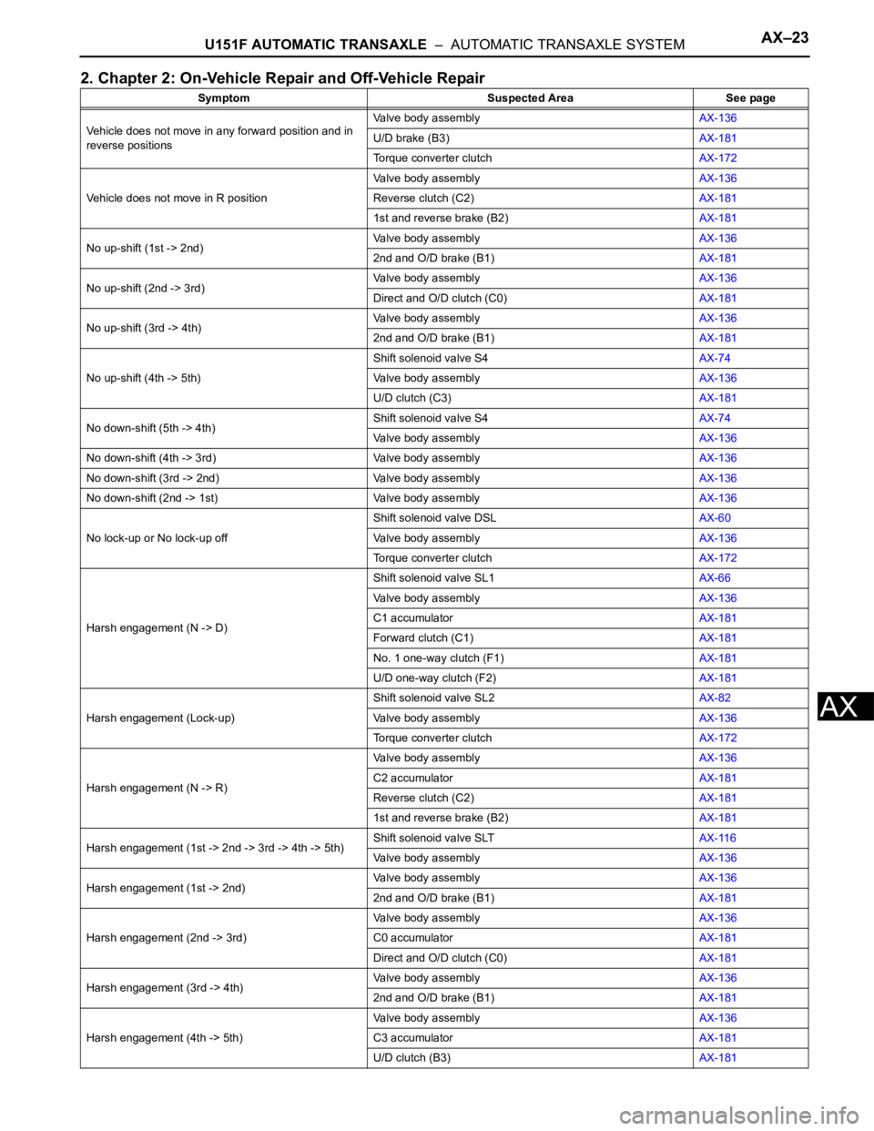
2. Chapter 2: On-Vehicle Repair and Off-Vehicle Repair
Symptom Suspected Area See page
Vehicle does not move in any forward position and in
reverse positionsValve body assemblyAX-136
U/D brake (B3)AX-181
Torque converter clutchAX-172
Vehicle does not move in R positionValve body assemblyAX-136
Reverse clutch (C2)AX-181
1st and reverse brake (B2)AX-181
No up-shift (1st -> 2nd)Valve body assemblyAX-136
2nd and O/D brake (B1)AX-181
No up-shift (2nd -> 3rd)Valve body assemblyAX-136
Direct and O/D clutch (C0)AX-181
No up-shift (3rd -> 4th)Valve body assemblyAX-136
2nd and O/D brake (B1)AX-181
No up-shift (4th -> 5th)Shift solenoid valve S4AX-74
Valve body assemblyAX-136
U/D clutch (C3)AX-181
No down-shift (5th -> 4th)Shift solenoid valve S4AX-74
Valve body assemblyAX-136
No down-shift (4th -> 3rd) Valve body assemblyAX-136
No down-shift (3rd -> 2nd) Valve body assemblyAX-136
No down-shift (2nd -> 1st) Valve body assemblyAX-136
No lock-up or No lock-up offShift solenoid valve DSLAX-60
Valve body assemblyAX-136
Torque converter clutchAX-172
Harsh engagement (N -> D)Shift solenoid valve SL1AX-66
Valve body assemblyAX-136
C1 accumulatorAX-181
Forward clutch (C1)AX-181
No. 1 one-way clutch (F1)AX-181
U/D one-way clutch (F2)AX-181
Harsh engagement (Lock-up)Shift solenoid valve SL2AX-82
Valve body assemblyAX-136
Torque converter clutchAX-172
Harsh engagement (N -> R)Valve body assemblyAX-136
C2 accumulatorAX-181
Reverse clutch (C2)AX-181
1st and reverse brake (B2)AX-181
Harsh engagement (1st -> 2nd -> 3rd -> 4th -> 5th)Shift solenoid valve SLTAX-116
Valve body assemblyAX-136
Harsh engagement (1st -> 2nd)Valve body assemblyAX-136
2nd and O/D brake (B1)AX-181
Harsh engagement (2nd -> 3rd)Valve body assemblyAX-136
C0 accumulatorAX-181
Direct and O/D clutch (C0)AX-181
Harsh engagement (3rd -> 4th)Valve body assemblyAX-136
2nd and O/D brake (B1)AX-181
Harsh engagement (4th -> 5th)Valve body assemblyAX-136
C3 accumulatorAX-181
U/D clutch (B3)AX-181
Page 1830 of 3000
AX–24U151F AUTOMATIC TRANSAXLE – AUTOMATIC TRANSAXLE SYSTEM
AX
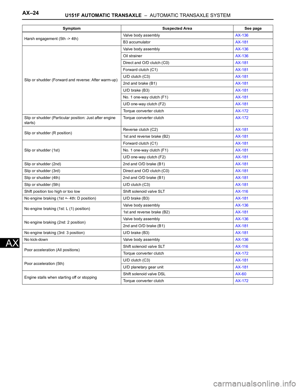
Harsh engagement (5th -> 4th)Valve body assemblyAX-136
B3 accumulatorAX-181
Slip or shudder (Forward and reverse: After warm-up)Valve body assemblyAX-136
Oil strainerAX-136
Direct and O/D clutch (C0)AX-181
Forward clutch (C1)AX-181
U/D clutch (C3)AX-181
2nd and brake (B1)AX-181
U/D brake (B3)AX-181
No. 1 one-way clutch (F1)AX-181
U/D one-way clutch (F2)AX-181
Torque converter clutchAX-172
Slip or shudder (Particular position: Just after engine
starts)Torque converter clutchAX-172
Slip or shudder (R position)Reverse clutch (C2)AX-181
1st and reverse brake (B2)AX-181
Slip or shudder (1st)Forward clutch (C1)AX-181
No. 1 one-way clutch (F1)AX-181
U/D one-way clutch (F2)AX-181
Slip or shudder (2nd) 2nd and O/D brake (B1)AX-181
Slip or shudder (3rd) Direct and O/D clutch (C0)AX-181
Slip or shudder (4th) 2nd and O/D brake (B1)AX-181
Slip or shudder (5th) U/D clutch (C3)AX-181
Shift position too high or too low Shift solenoid valve SLTAX-116
No engine braking (1st +- 4th: D position) U/D brake (B3)AX-181
No engine braking (1st: L (1) position)Valve body assemblyAX-136
1st and reverse brake (B2)AX-181
No engine braking (2nd: 2 position)Valve body assemblyAX-136
2nd and O/D brake (B1)AX-181
No engine braking (3rd: 3 position) U/D brake (B3)AX-181
No kick-down Valve body assemblyAX-136
Poor acceleration (All positions)Shift solenoid valve SLTAX-116
Torque converter clutchAX-172
Poor acceleration (5th)U/D clutch (C3)AX-181
U/D planetary gear unitAX-181
Engine stalls when starting off or stoppingShift solenoid valve DSLAX-60
Torque converter clutchAX-172 Symptom Suspected Area See page
Page 1831 of 3000

AX–142U151F AUTOMATIC TRANSAXLE – SHIFT LOCK SYSTEM
AX
SHIFT LOCK SYSTEM
ON-VEHICLE INSPECTION
1. CHECK SHIFT LOCK OPERATION
(a) Move the shift lever to the P position.
(b) Turn the ignition switch to the LOCK position.
(c) Check that the shift lever cannot be moved to any
position other than P.
(d) Turn the ignition switch to the on position, depress
the brake pedal and check that the shift lever can be
moved to another position. If operation can not be
done as specified, inspect the shift lock control unit.
2. CHECK SHIFT LOCK RELEASE BUTTON
OPERATION
(a) Using a small screwdriver, remove the shift lock
release cover.
(b) When operating the shift lever with the shift lock
release button pressed, check that the lever can be
moved to any position other than P.
If operation can not be done as specified, check the
shift lever assembly installation condition.
3. CHECK KEY INTERLOCK OPERATION
(a) Turn the ignition switch to the ON position.
(b) Depress the brake pedal and move the shift lever to
any position other than P.
(c) Check that the ignition key cannot be turned to the
LOCK position.
(d) Move the shift lever to the P position, turn the
ignition key to the LOCK position and check that the
ignition key can be removed.
If operation cannot be done as specified, inspect the
shift lock control unit.
4. INSPECT SHIFT LOCK CONTROL UNIT ASSEMBLY
(a) Measure the voltage according to the value(s) in the
table below.
HINT:
Do not disconnect the shift lock control unit
assembly connector.
Voltage
C098999E11
Terminal Measuring Condition Voltage (V)
6 (ACC) - 8 (E) Ignition switch ACC10 to 14
6 (ACC) - 8 (E) Ignition switch OFFBelow 1
7 (STP) - 8 (E) Depress brake pedal10 to 14
7 (STP) - 8 (E) Release brake pedalBelow 1
12 (KLS+) - 8 (E)1. Ignition switch ACC and shift lever P position
2. Ignition switch ACC and shift lever except P position
3. Ignition switch ACC and shift lever except P position (After approx. 1 second)Below 1
7.5 to 11
6 to 9
Page 1833 of 3000
U151F AUTOMATIC TRANSAXLE – AUTOMATIC TRANSAXLE SYSTEMAX–25
AX
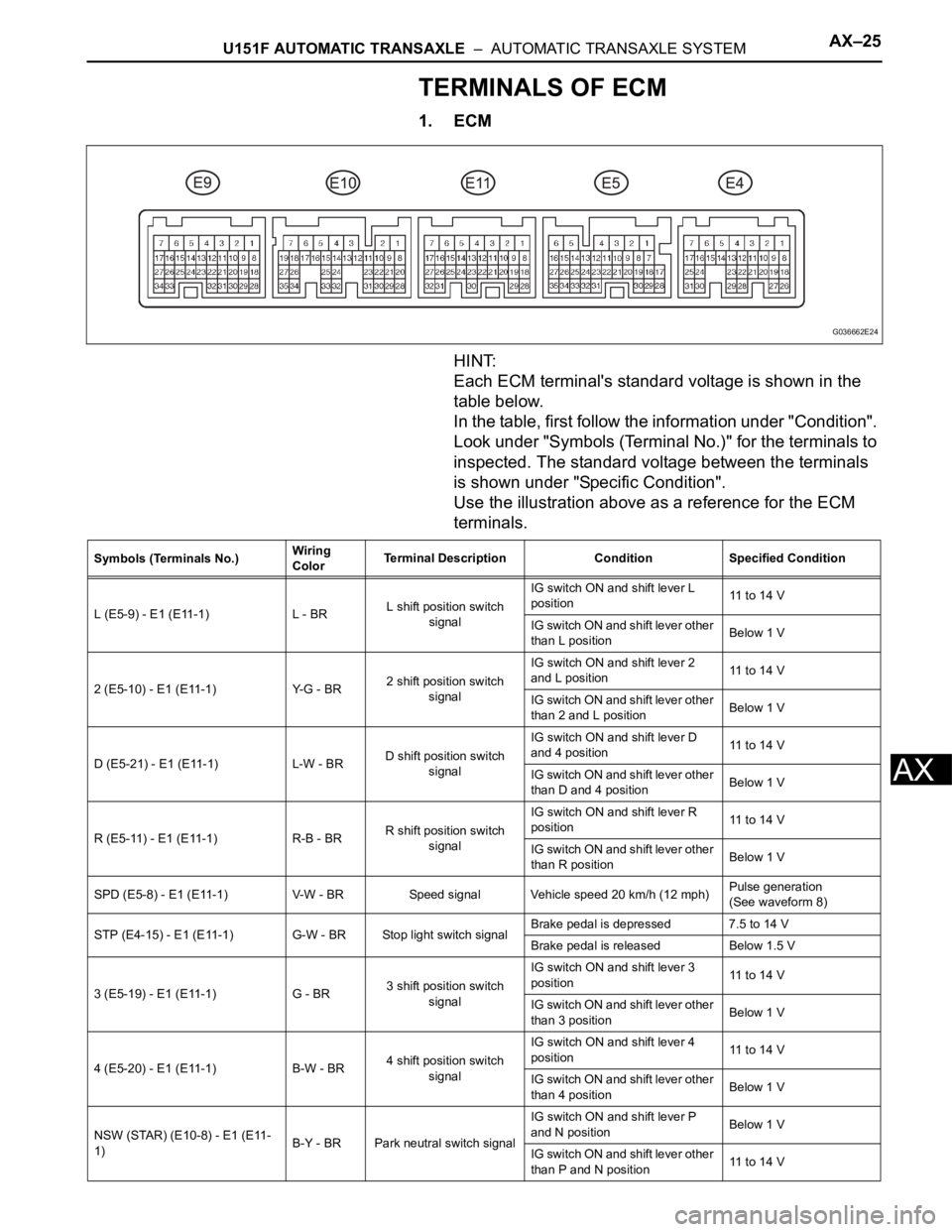
TERMINALS OF ECM
1. ECM
HINT:
Each ECM terminal's standard voltage is shown in the
table below.
In the table, first follow the information under "Condition".
Look under "Symbols (Terminal No.)" for the terminals to
inspected. The standard voltage between the terminals
is shown under "Specific Condition".
Use the illustration above as a reference for the ECM
terminals.
G036662E24
Symbols (Terminals No.)Wiring
ColorTerminal Description Condition Specified Condition
L (E5-9) - E1 (E11-1) L - BRL shift position switch
signalIG switch ON and shift lever L
position11 to 14 V
IG switch ON and shift lever other
than L positionBelow 1 V
2 (E5-10) - E1 (E11-1) Y-G - BR2 shift position switch
signalIG switch ON and shift lever 2
and L position11 to 14 V
IG switch ON and shift lever other
than 2 and L positionBelow 1 V
D (E5-21) - E1 (E11-1) L-W - BRD shift position switch
signalIG switch ON and shift lever D
and 4 position11 to 14 V
IG switch ON and shift lever other
than D and 4 positionBelow 1 V
R (E5-11) - E1 (E11-1) R-B - BRR shift position switch
signalIG switch ON and shift lever R
position11 to 14 V
IG switch ON and shift lever other
than R positionBelow 1 V
SPD (E5-8) - E1 (E11-1) V-W - BR Speed signal Vehicle speed 20 km/h (12 mph)Pulse generation
(See waveform 8)
STP (E4-15) - E1 (E11-1) G-W - BR Stop light switch signalBrake pedal is depressed 7.5 to 14 V
Brake pedal is released Below 1.5 V
3 (E5-19) - E1 (E11-1) G - BR3 shift position switch
signalIG switch ON and shift lever 3
position11 to 14 V
IG switch ON and shift lever other
than 3 positionBelow 1 V
4 (E5-20) - E1 (E11-1) B-W - BR4 shift position switch
signalIG switch ON and shift lever 4
position11 to 14 V
IG switch ON and shift lever other
than 4 positionBelow 1 V
NSW (STAR) (E10-8) - E1 (E11-
1)B-Y - BR Park neutral switch signalIG switch ON and shift lever P
and N positionBelow 1 V
IG switch ON and shift lever other
than P and N position11 to 14 V
Page 1841 of 3000

AX–150U151F AUTOMATIC TRANSAXLE – SHIFT LEVER
AX
ADJUSTMENT
1. INSPECT SHIFT LEVER POSITION
(a) When shifting from P to R position only with ignition
switch ON and brake pedal, make sure that the
shifting lever moves smoothly and can be
moderately operated.
(b) When starting engine, make sure that the vehicle
moves forward when shifting from N to D position
and moves rearward when shifting to R position.
2. ADJUST SHIFT LEVER POSITION
(a) Loosen the nut on the control shaft lever.
(b) Push the control shaft fully downward.
(c) Return the control shaft lever 2 notches to the N
position.
(d) While pushing the control cable end up with the shift
lever in the N position, install it to the control shaft
lever with the nut.
Torque: 13 N*m (132.6 kgf*cm, 9.5 ft.*lbf)
NOTICE:
• If the control cable end is excessively pushed
up, the shift lever can not be adjusted.
• When tightening the nut, confirm that the
control cable is properly stretched.
(e) Start the engine and make sure that the vehicle
moves forward when shifting the lever from the N to
D position and moves rearward when shifting it to
the R position.
D025118
D025119
C098998