check oil TOYOTA SIENNA 2007 Service Repair Manual
[x] Cancel search | Manufacturer: TOYOTA, Model Year: 2007, Model line: SIENNA, Model: TOYOTA SIENNA 2007Pages: 3000, PDF Size: 52.26 MB
Page 2657 of 3000
PB–18PARKING BRAKE – PARKING BRAKE ASSEMBLY
PB
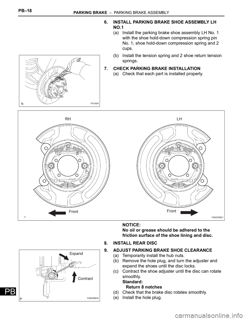
6. INSTALL PARKING BRAKE SHOE ASSEMBLY LH
NO.1
(a) Install the parking brake shoe assembly LH No. 1
with the shoe hold-down compression spring pin
No. 1, shoe hold-down compression spring and 2
cups.
(b) Install the tension spring and 2 shoe return tension
springs.
7. CHECK PARKING BRAKE INSTALLATION
(a) Check that each part is installed properly.
NOTICE:
No oil or grease should be adhered to the
friction surface of the shoe lining and disc.
8. INSTALL REAR DISC
9. ADJUST PARKING BRAKE SHOE CLEARANCE
(a) Temporarily install the hub nuts.
(b) Remove the hole plug, and turn the adjuster and
expand the shoes until the disc locks.
(c) Contract the shoe adjuster until the disc can rotate
smoothly.
Standard:
Return 8 notches
(d) Check that the brake disc rotates smoothly.
(e) Install the hole plug.
F012039
F045276E01
F040026E02
Page 2668 of 3000
PB–18PARKING BRAKE – PARKING BRAKE ASSEMBLY
PB
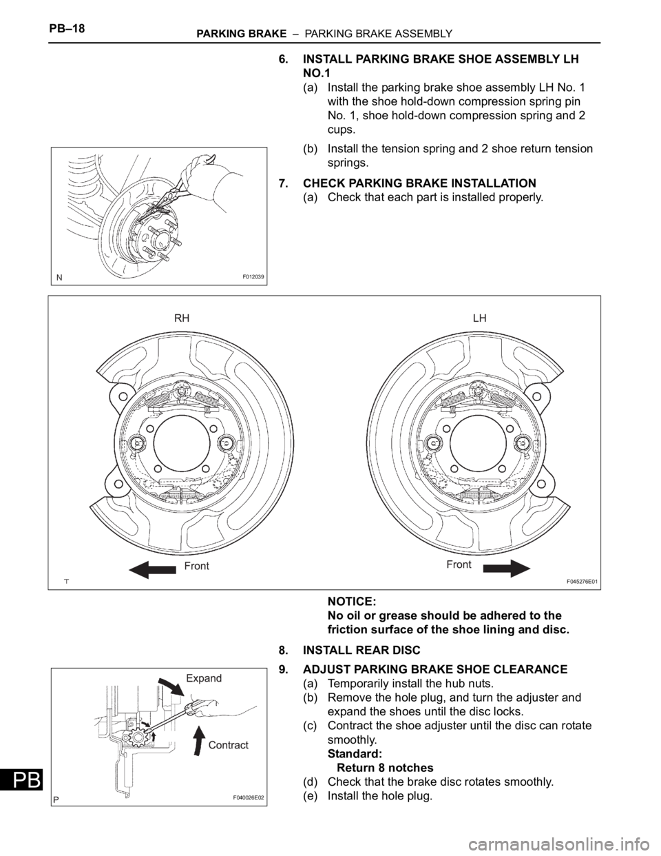
6. INSTALL PARKING BRAKE SHOE ASSEMBLY LH
NO.1
(a) Install the parking brake shoe assembly LH No. 1
with the shoe hold-down compression spring pin
No. 1, shoe hold-down compression spring and 2
cups.
(b) Install the tension spring and 2 shoe return tension
springs.
7. CHECK PARKING BRAKE INSTALLATION
(a) Check that each part is installed properly.
NOTICE:
No oil or grease should be adhered to the
friction surface of the shoe lining and disc.
8. INSTALL REAR DISC
9. ADJUST PARKING BRAKE SHOE CLEARANCE
(a) Temporarily install the hub nuts.
(b) Remove the hole plug, and turn the adjuster and
expand the shoes until the disc locks.
(c) Contract the shoe adjuster until the disc can rotate
smoothly.
Standard:
Return 8 notches
(d) Check that the brake disc rotates smoothly.
(e) Install the hole plug.
F012039
F045276E01
F040026E02
Page 2701 of 3000
POWER STEERING – RACK AND PINION POWER STEERING GEARPS–33
PS
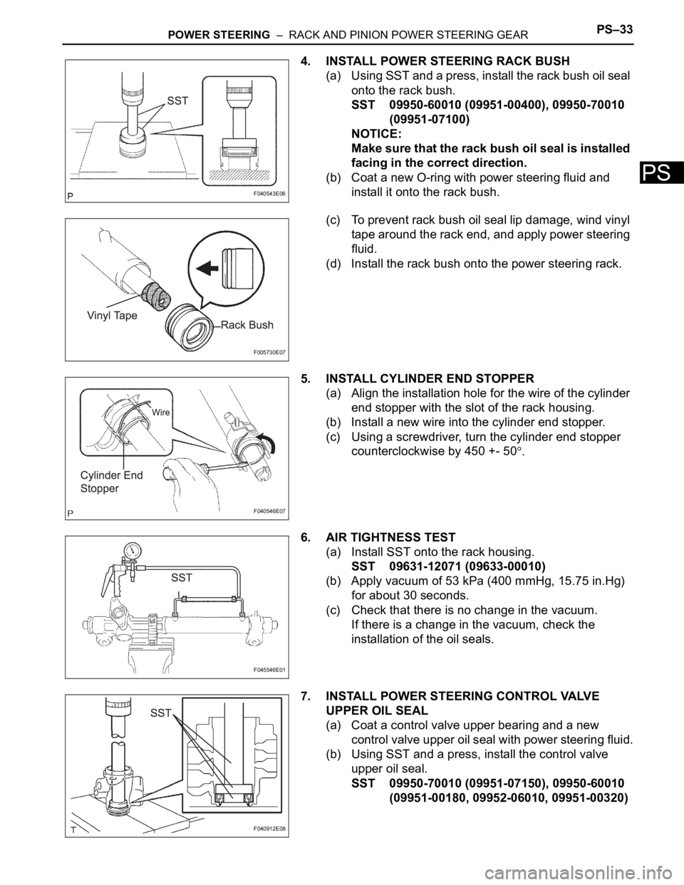
4. INSTALL POWER STEERING RACK BUSH
(a) Using SST and a press, install the rack bush oil seal
onto the rack bush.
SST 09950-60010 (09951-00400), 09950-70010
(09951-07100)
NOTICE:
Make sure that the rack bush oil seal is installed
facing in the correct direction.
(b) Coat a new O-ring with power steering fluid and
install it onto the rack bush.
(c) To prevent rack bush oil seal lip damage, wind vinyl
tape around the rack end, and apply power steering
fluid.
(d) Install the rack bush onto the power steering rack.
5. INSTALL CYLINDER END STOPPER
(a) Align the installation hole for the wire of the cylinder
end stopper with the slot of the rack housing.
(b) Install a new wire into the cylinder end stopper.
(c) Using a screwdriver, turn the cylinder end stopper
counterclockwise by 450 +- 50
.
6. AIR TIGHTNESS TEST
(a) Install SST onto the rack housing.
SST 09631-12071 (09633-00010)
(b) Apply vacuum of 53 kPa (400 mmHg, 15.75 in.Hg)
for about 30 seconds.
(c) Check that there is no change in the vacuum.
If there is a change in the vacuum, check the
installation of the oil seals.
7. INSTALL POWER STEERING CONTROL VALVE
UPPER OIL SEAL
(a) Coat a control valve upper bearing and a new
control valve upper oil seal with power steering fluid.
(b) Using SST and a press, install the control valve
upper oil seal.
SST 09950-70010 (09951-07150), 09950-60010
(09951-00180, 09952-06010, 09951-00320)
F040543E06
F005730E07
F040546E07
F045546E01
F040912E08
Page 2725 of 3000
PS–14POWER STEERING – VANE PUMP
PS
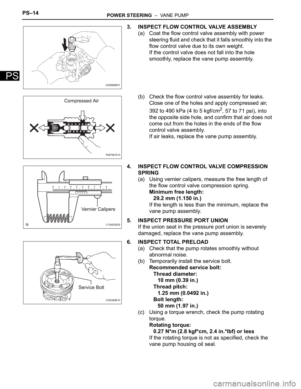
3. INSPECT FLOW CONTROL VALVE ASSEMBLY
(a) Coat the flow control valve assembly with power
steering fluid and check that it falls smoothly into the
flow control valve due to its own weight.
If the control valve does not fall into the hole
smoothly, replace the vane pump assembly.
(b) Check the flow control valve assembly for leaks.
Close one of the holes and apply compressed air,
392 to 490 kPa (4 to 5 kgf/cm
2, 57 to 71 psi), into
the opposite side hole, and confirm that air does not
come out from the holes in the ends of the flow
control valve assembly.
If air leaks, replace the vane pump assembly.
4. INSPECT FLOW CONTROL VALVE COMPRESSION
SPRING
(a) Using vernier calipers, measure the free length of
the flow control valve compression spring.
Minimum free length:
29.2 mm (1.150 in.)
If the length is less than the minimum, replace the
vane pump assembly.
5. INSPECT PRESSURE PORT UNION
If the union seat in the pressure port union is severely
damaged, replace the vane pump assembly.
6. INSPECT TOTAL PRELOAD
(a) Check that the pump rotates smoothly without
abnormal noise.
(b) Temporarily install the service bolt.
Recommended service bolt:
Thread diameter:
10 mm (0.39 in.)
Thread pitch:
1.25 mm (0.0492 in.)
Bolt length:
50 mm (1.97 in.)
(c) Using a torque wrench, check the pump rotating
torque.
Rotating torque:
0.27 N*m (2.8 kgf*cm, 2.4 in.*lbf) or less
If the rotating torque is not as specified, check the
vane pump housing oil seal.
G030668E01
R007591E10
C132032E02
C053369E10
Page 2744 of 3000
POWER STEERING – RACK AND PINION POWER STEERING GEARPS–33
PS
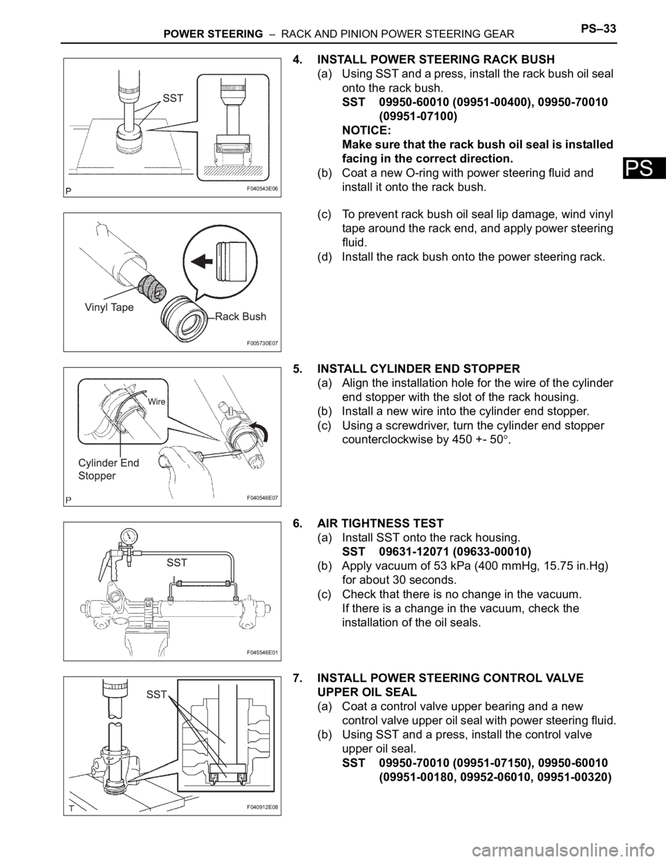
4. INSTALL POWER STEERING RACK BUSH
(a) Using SST and a press, install the rack bush oil seal
onto the rack bush.
SST 09950-60010 (09951-00400), 09950-70010
(09951-07100)
NOTICE:
Make sure that the rack bush oil seal is installed
facing in the correct direction.
(b) Coat a new O-ring with power steering fluid and
install it onto the rack bush.
(c) To prevent rack bush oil seal lip damage, wind vinyl
tape around the rack end, and apply power steering
fluid.
(d) Install the rack bush onto the power steering rack.
5. INSTALL CYLINDER END STOPPER
(a) Align the installation hole for the wire of the cylinder
end stopper with the slot of the rack housing.
(b) Install a new wire into the cylinder end stopper.
(c) Using a screwdriver, turn the cylinder end stopper
counterclockwise by 450 +- 50
.
6. AIR TIGHTNESS TEST
(a) Install SST onto the rack housing.
SST 09631-12071 (09633-00010)
(b) Apply vacuum of 53 kPa (400 mmHg, 15.75 in.Hg)
for about 30 seconds.
(c) Check that there is no change in the vacuum.
If there is a change in the vacuum, check the
installation of the oil seals.
7. INSTALL POWER STEERING CONTROL VALVE
UPPER OIL SEAL
(a) Coat a control valve upper bearing and a new
control valve upper oil seal with power steering fluid.
(b) Using SST and a press, install the control valve
upper oil seal.
SST 09950-70010 (09951-07150), 09950-60010
(09951-00180, 09952-06010, 09951-00320)
F040543E06
F005730E07
F040546E07
F045546E01
F040912E08
Page 2915 of 3000
AIR CONDITIONING – REFRIGERANTAC–171
AC
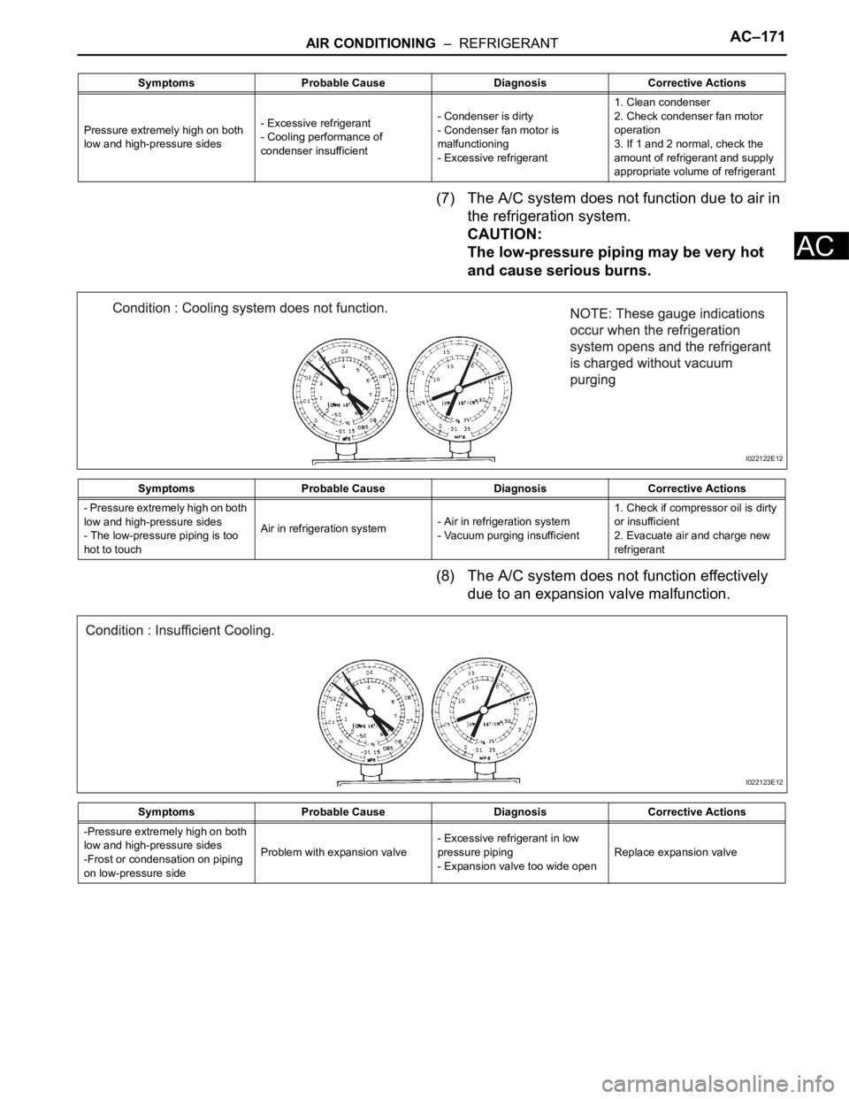
(7) The A/C system does not function due to air in
the refrigeration system.
CAUTION:
The low-pressure piping may be very hot
and cause serious burns.
(8) The A/C system does not function effectively
due to an expansion valve malfunction.
Symptoms Probable Cause Diagnosis Corrective Actions
Pressure extremely high on both
low and high-pressure sides- Excessive refrigerant
- Cooling performance of
condenser insufficient- Condenser is dirty
- Condenser fan motor is
malfunctioning
- Excessive refrigerant1. Clean condenser
2. Check condenser fan motor
operation
3. If 1 and 2 normal, check the
amount of refrigerant and supply
appropriate volume of refrigerant
Symptoms Probable Cause Diagnosis Corrective Actions
- Pressure extremely high on both
low and high-pressure sides
- The low-pressure piping is too
hot to touchAir in refrigeration system- Air in refrigeration system
- Vacuum purging insufficient1. Check if compressor oil is dirty
or insufficient
2. Evacuate air and charge new
refrigerant
I022122E12
Symptoms Probable Cause Diagnosis Corrective Actions
-Pressure extremely high on both
low and high-pressure sides
-Frost or condensation on piping
on low-pressure sideProblem with expansion valve- Excessive refrigerant in low
pressure piping
- Expansion valve too wide openReplace expansion valve
I022123E12
Page 2917 of 3000
AIR CONDITIONING – REFRIGERANTAC–173
AC
REPLACEMENT
1. DISCHARGE REFRIGERANT FROM
REFRIGERATION SYSTEM
SST 07110-58060 (07117-58080, 07117-58090,
07117-78050, 07117-88060, 07117-88070,
07117-88080)
(a) Turn the A/C switch to ON.
(b) Operating the cooler compressor at the engine rpm
of approx. 1,000 for 5 to 6 minutes, circulate the
refrigerant and collect the compressor oil remaining
in each component into the cooler compressor as
much as possible.
(c) Stop the engine.
(d) Let the refrigerant gas out.
SST 07110-58060 (07117-58080, 07117-78050,
07117-88060, 07117-88070, 07117-88080)
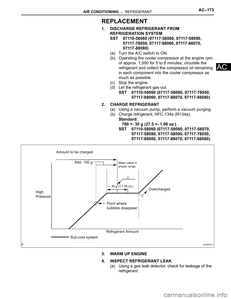
2. CHARGE REFRIGERANT
(a) Using a vacuum pump, perform a vacuum purging.
(b) Charge refrigerant, HFC-134a (R134a).
Standard:
780 +- 30 g (27.5 +- 1.06 oz.)
SST 07110-58060 (07117-58060, 07117-58070,
07117-58080, 07117-58090, 07117-78050,
07117-88060, 07117-88070, 07117-88080)
3. WARM UP ENGINE
4. INSPECT REFRIGERANT LEAK
(a) Using a gas leak detector, check for leakage of the
refrigerant.
I030082E10
Page 2956 of 3000
AC–230AIR CONDITIONING – COMPRESSOR AND MAGNETIC CLUTCH
AC
2. INSPECT COMPRESSOR OIL
(a) When replacing the compressor and magnetic
clutch with a new one, after gradually removing the
refrigerant gas from the service valve, drain the
following amount of oil from the new compressor
and magnetic clutch before installation.
Standard:
(Oil capacity inside new compressor and
magnetic clutch:
225 + 15 cc (7.6 + 0.5 fl.oz.)) - (Remaining oil
amount in the removed compressor and
magnetic clutch) = (Oil amount to be
removed when replacing)
NOTICE:
• When checking the compressor oil level,
observe the precautions on the cooler
removal / installation.
• Because compressor oil remains in the pipes
of the vehicle, if a new compressor and
magnetic clutch is installed without removing
some oil inside, the oil amount becomes
excessive, preventing heat exchange in the
refrigerant cycle and causing refrigerant
failure.
• If the remaining oil in the removed
compressor and magnetic clutch is too small
in volume, check for oil leakage.
• Be sure to use ND-OIL 8 for compressor oil.
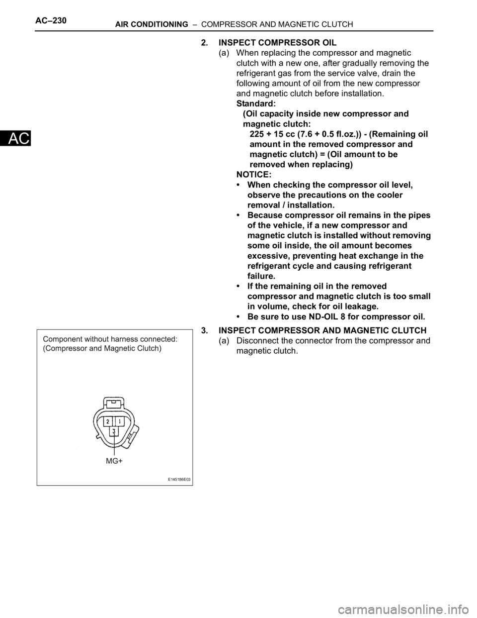
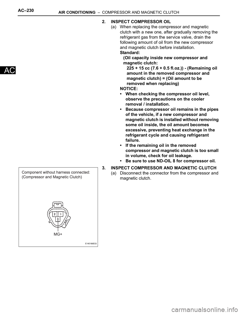
3. INSPECT COMPRESSOR AND MAGNETIC CLUTCH
(a) Disconnect the connector from the compressor and
magnetic clutch.
E145186E03
Page 2970 of 3000
AC–230AIR CONDITIONING – COMPRESSOR AND MAGNETIC CLUTCH
AC
2. INSPECT COMPRESSOR OIL
(a) When replacing the compressor and magnetic
clutch with a new one, after gradually removing the
refrigerant gas from the service valve, drain the
following amount of oil from the new compressor
and magnetic clutch before installation.
Standard:
(Oil capacity inside new compressor and
magnetic clutch:
225 + 15 cc (7.6 + 0.5 fl.oz.)) - (Remaining oil
amount in the removed compressor and
magnetic clutch) = (Oil amount to be
removed when replacing)
NOTICE:
• When checking the compressor oil level,
observe the precautions on the cooler
removal / installation.
• Because compressor oil remains in the pipes
of the vehicle, if a new compressor and
magnetic clutch is installed without removing
some oil inside, the oil amount becomes
excessive, preventing heat exchange in the
refrigerant cycle and causing refrigerant
failure.
• If the remaining oil in the removed
compressor and magnetic clutch is too small
in volume, check for oil leakage.
• Be sure to use ND-OIL 8 for compressor oil.
3. INSPECT COMPRESSOR AND MAGNETIC CLUTCH
(a) Disconnect the connector from the compressor and
magnetic clutch.
E145186E03