check oil TOYOTA SIENNA 2007 Service Repair Manual
[x] Cancel search | Manufacturer: TOYOTA, Model Year: 2007, Model line: SIENNA, Model: TOYOTA SIENNA 2007Pages: 3000, PDF Size: 52.26 MB
Page 2023 of 3000
TRANSFER – TRANSFER UNITTF–33
TF
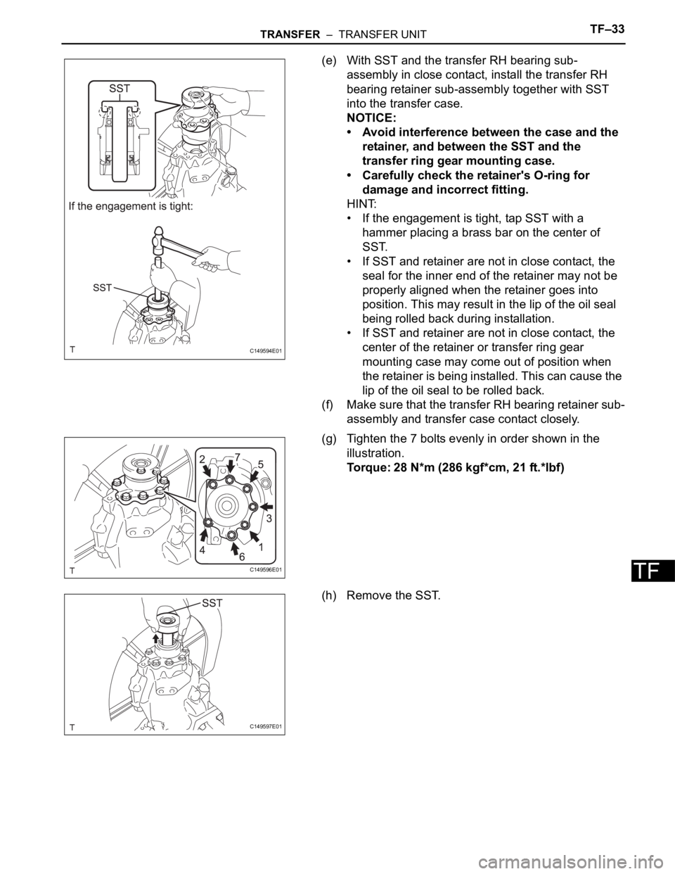
(e) With SST and the transfer RH bearing sub-
assembly in close contact, install the transfer RH
bearing retainer sub-assembly together with SST
into the transfer case.
NOTICE:
• Avoid interference between the case and the
retainer, and between the SST and the
transfer ring gear mounting case.
• Carefully check the retainer's O-ring for
damage and incorrect fitting.
HINT:
• If the engagement is tight, tap SST with a
hammer placing a brass bar on the center of
SST.
• If SST and retainer are not in close contact, the
seal for the inner end of the retainer may not be
properly aligned when the retainer goes into
position. This may result in the lip of the oil seal
being rolled back during installation.
• If SST and retainer are not in close contact, the
center of the retainer or transfer ring gear
mounting case may come out of position when
the retainer is being installed. This can cause the
lip of the oil seal to be rolled back.
(f) Make sure that the transfer RH bearing retainer sub-
assembly and transfer case contact closely.
(g) Tighten the 7 bolts evenly in order shown in the
illustration.
Torque: 28 N*m (286 kgf*cm, 21 ft.*lbf)
(h) Remove the SST.
C149594E01
C149596E01
C149597E01
Page 2025 of 3000
TRANSFER – TRANSFER UNITTF–35
TF
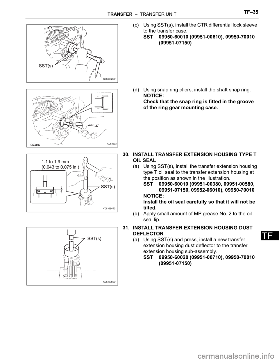
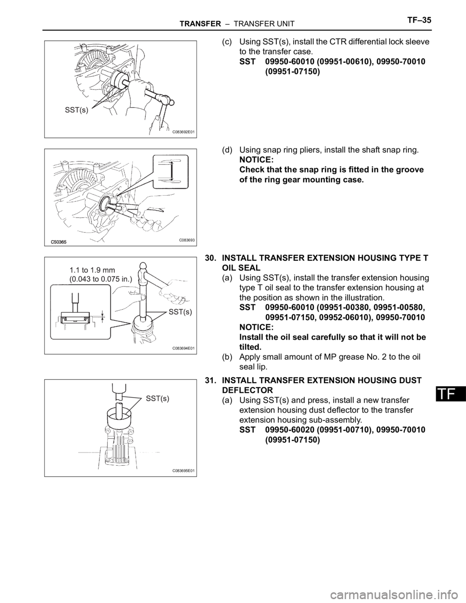
(c) Using SST(s), install the CTR differential lock sleeve
to the transfer case.
SST 09950-60010 (09951-00610), 09950-70010
(09951-07150)
(d) Using snap ring pliers, install the shaft snap ring.
NOTICE:
Check that the snap ring is fitted in the groove
of the ring gear mounting case.
30. INSTALL TRANSFER EXTENSION HOUSING TYPE T
OIL SEAL
(a) Using SST(s), install the transfer extension housing
type T oil seal to the transfer extension housing at
the position as shown in the illustration.
SST 09950-60010 (09951-00380, 09951-00580,
09951-07150, 09952-06010), 09950-70010
NOTICE:
Install the oil seal carefully so that it will not be
tilted.
(b) Apply small amount of MP grease No. 2 to the oil
seal lip.
31. INSTALL TRANSFER EXTENSION HOUSING DUST
DEFLECTOR
(a) Using SST(s) and press, install a new transfer
extension housing dust deflector to the transfer
extension housing sub-assembly.
SST 09950-60020 (09951-00710), 09950-70010
(09951-07150)
C083692E01
C083693
C083694E01
C083695E01
Page 2029 of 3000
TRANSFER – TRANSFER OILTF–3
TF
TRANSFER OIL
ON-VEHICLE INSPECTION
1. INSPECT TRANSFER OIL
(a) Remove the No. 1 plug and gasket.
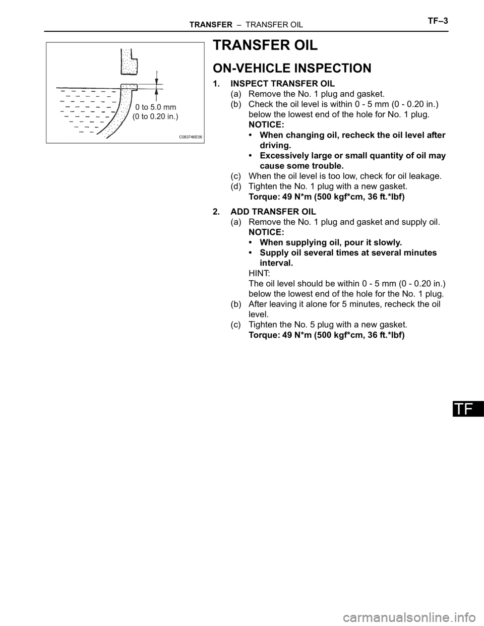
(b) Check the oil level is within 0 - 5 mm (0 - 0.20 in.)
below the lowest end of the hole for No. 1 plug.
NOTICE:
• When changing oil, recheck the oil level after
driving.
• Excessively large or small quantity of oil may
cause some trouble.
(c) When the oil level is too low, check for oil leakage.
(d) Tighten the No. 1 plug with a new gasket.
Torque: 49 N*m (500 kgf*cm, 36 ft.*lbf)
2. ADD TRANSFER OIL
(a) Remove the No. 1 plug and gasket and supply oil.
NOTICE:
• When supplying oil, pour it slowly.
• Supply oil several times at several minutes
interval.
HINT:
The oil level should be within 0 - 5 mm (0 - 0.20 in.)
below the lowest end of the hole for the No. 1 plug.
(b) After leaving it alone for 5 minutes, recheck the oil
level.
(c) Tighten the No. 5 plug with a new gasket.
Torque: 49 N*m (500 kgf*cm, 36 ft.*lbf)
C083746E06
Page 2032 of 3000
TRANSFER – TRANSFER ASSEMBLYTF–9
TF
INSTALLATION
1. INSTALL TRANSFER ASSEMBLY
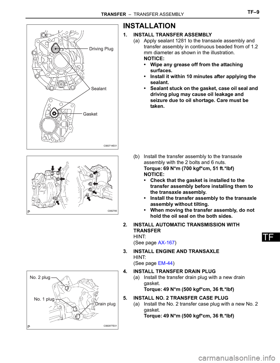
(a) Apply sealant 1281 to the transaxle assembly and
transfer assembly in continuous beaded from of 1.2
mm diameter as shown in the illustration.
NOTICE:
• Wipe any grease off from the attaching
surfaces.
• Install it within 10 minutes after applying the
sealant.
• Sealant stuck on the gasket, case oil seal and
driving plug may cause oil leakage and
seizure due to oil shortage. Care must be
taken.
(b) Install the transfer assembly to the transaxle
assembly with the 2 bolts and 6 nuts.
Torque: 69 N*m (700 kgf*cm, 51 ft.*lbf)
NOTICE:
• Check that the gasket is installed to the
transfer assembly before installing them to
the transaxle assembly.
• Install the transfer assembly to the transaxle
assembly without tilting.
• When moving the transfer assembly, do not
hold the oil seal on the both sides.
2. INSTALL AUTOMATIC TRANSMISSION WITH
TRANSFER
HINT:
(See page AX-167)
3. INSTALL ENGINE AND TRANSAXLE
HINT:
(See page EM-44)
4. INSTALL TRANSFER DRAIN PLUG
(a) Install the transfer drain plug with a new drain
gasket.
Torque: 49 N*m (500 kgf*cm, 36 ft.*lbf)
5. INSTALL NO. 2 TRANSFER CASE PLUG
(a) Install the No. 2 transfer case plug with a new No. 2
gasket.
Torque: 49 N*m (500 kgf*cm, 36 ft.*lbf)
C083714E01
C082785
C082977E01
Page 2033 of 3000
TF–10TRANSFER – TRANSFER ASSEMBLY
TF
6. INSTALL NO. 1 TRANSFER CASE PLUG
(a) Add oil up to 0 to 5 mm below the lower side of the
plug hole.
Oil quantity:
0.9 L (0.95 US qts, 0.71 lmp. qts)
HINT:
When adding oil, pour it slowly.
(b) Install the No. 1 transfer case plug with a new No. 1
gasket.
Torque: 49 N*m (500 kgf*cm, 36 ft.*lbf)
7. INSPECT AND ADJUST FRONT WHEEL ALIGNMENT
HINT:
(See page SP-4)
8. CHECK ABS SPEED SENSOR SIGNAL
HINT:
(See page BC-3)
Page 2047 of 3000
TF–24TRANSFER – TRANSFER UNIT
TF
(d) If the preload is insufficient, even though the
tightening torque of the transfer gear nut exceeds
the maximum of the standard value., loosen the
transfer gear nut and apply gear oil SAE 90 (GL-5)
to the transfer gear nut and the screw thread and
the base of driven pinion. And then repeat the
preceding operation . If the tightening torque is
bearing spacer with anew one and adjust it.
Torque: 378 N*m (3.855 kgf*cm, 279 ft.*lbf)
9. INSTALL RING GEAR
(a) Heat the ring gear in boiling water from 90 to 100
C
(194 to 212
F).
(b) Completely remove grease and moisture on the
contact surfaces of the ring gear and the transfer
ring gear mounting case.
(c) Align the matchmarks on the ring gear and transfer
ring gear mounting case and quickly assemble
them.
(d) Tighten the 12 bolts.
Torque: 78 N*m (790 kgf*cm, 57 ft.*lbf)
NOTICE:
• Tighten the bolts in diagonal order in splitting
several times.
• After the ring gear has well cooled down, fully
tighten the bolts.
• Make the bolt heads in order to check if they
are retightened or not.
10. INSTALL CENTER DIFFERENTIAL CASE TAPERED
ROLLER BEARING
(a) Using SST(s) and a press, install the inner race of
the center differential case tapered roller bearing to
the transfer ring gear mounting case.
SST 09506-35010, 09950-60010 (09951-00430),
09223-00010
NOTICE:
When replacing the inner race, replace it
together with the outer race.
C083651E01
C083652E01
C124918E01
Page 2054 of 3000
TRANSFER – TRANSFER UNITTF–31
TF
19. REMOVE CENTER DIFFERENTIAL CASE TAPERED
ROLLER BEARING
(a) Fix the transfer RH bearing retainer sub-assembly
in a vise.
(b) Using SST(s), remove the center differential case
tapered roller bearing RH outer race and transfer
ring gear mounting case washer No. 2 from the
transfer RH bearing retainer sub-assembly.
SST 09308-00010
20. INSTALL SIDE GEAR SHAFT HOLDER BEARING
(a) Install the side gear shaft holder bearing to the
transfer RH bearing retainer sub-assembly.
(b) Using snap ring pliers, install the side gear shaft
holder hole snap ring.
HINT:
Check that the side gear shaft holder hole snap ring
fits in the groove of the transfer RH bearing retainer
sub-assembly.
21. INSTALL TRANSFER RH BEARING RETAINER OIL
SEAL
(a) Using SST(s) and a press, install the transfer RH
bearing retainer oil seal No. 2 to the transfer RH
bearing retainer sub-assembly.
SST 09950-60010 (09951-00350, 09951-00560,
09952-06010), 09950-70010 (09951-07150)
NOTICE:
Carefully press-fit so that the oil seal will not be
tilted.
(b) Apply small amount of MP grease No. 2 to the oil
seal lip.
22. INSTALL NO. 2 TRANSFER RING GEAR MOUNTING
CASE WASHER
(a) Install the No. 2 selected transfer ring gear
mounting washer to the transfer RH bearing retainer
sub-assembly.
23. INSTALL CENTER DIFFERENTIAL CASE TAPERED
ROLLER BEARING
(a) Using SST(s) and a press, install the center
differential case tapered roller bearing RH outer
race to the transfer RH bearing retainer sub-
assembly.
SST 09950-60010 (09951-00620), 09950-70010
(09951-07150)
C083688E01
C083699
C083689E01
C083690E01
Page 2056 of 3000
TRANSFER – TRANSFER UNITTF–33
TF
(e) With SST and the transfer RH bearing sub-
assembly in close contact, install the transfer RH
bearing retainer sub-assembly together with SST
into the transfer case.
NOTICE:
• Avoid interference between the case and the
retainer, and between the SST and the
transfer ring gear mounting case.
• Carefully check the retainer's O-ring for
damage and incorrect fitting.
HINT:
• If the engagement is tight, tap SST with a
hammer placing a brass bar on the center of
SST.
• If SST and retainer are not in close contact, the
seal for the inner end of the retainer may not be
properly aligned when the retainer goes into
position. This may result in the lip of the oil seal
being rolled back during installation.
• If SST and retainer are not in close contact, the
center of the retainer or transfer ring gear
mounting case may come out of position when
the retainer is being installed. This can cause the
lip of the oil seal to be rolled back.
(f) Make sure that the transfer RH bearing retainer sub-
assembly and transfer case contact closely.
(g) Tighten the 7 bolts evenly in order shown in the
illustration.
Torque: 28 N*m (286 kgf*cm, 21 ft.*lbf)
(h) Remove the SST.
C149594E01
C149596E01
C149597E01
Page 2058 of 3000
TRANSFER – TRANSFER UNITTF–35
TF
(c) Using SST(s), install the CTR differential lock sleeve
to the transfer case.
SST 09950-60010 (09951-00610), 09950-70010
(09951-07150)
(d) Using snap ring pliers, install the shaft snap ring.
NOTICE:
Check that the snap ring is fitted in the groove
of the ring gear mounting case.
30. INSTALL TRANSFER EXTENSION HOUSING TYPE T
OIL SEAL
(a) Using SST(s), install the transfer extension housing
type T oil seal to the transfer extension housing at
the position as shown in the illustration.
SST 09950-60010 (09951-00380, 09951-00580,
09951-07150, 09952-06010), 09950-70010
NOTICE:
Install the oil seal carefully so that it will not be
tilted.
(b) Apply small amount of MP grease No. 2 to the oil
seal lip.
31. INSTALL TRANSFER EXTENSION HOUSING DUST
DEFLECTOR
(a) Using SST(s) and press, install a new transfer
extension housing dust deflector to the transfer
extension housing sub-assembly.
SST 09950-60020 (09951-00710), 09950-70010
(09951-07150)
C083692E01
C083693
C083694E01
C083695E01
Page 2069 of 3000
PROPELLER SHAFT – PROPELLER SHAFT ASSEMBLY (for 4WD)PR–9
PR
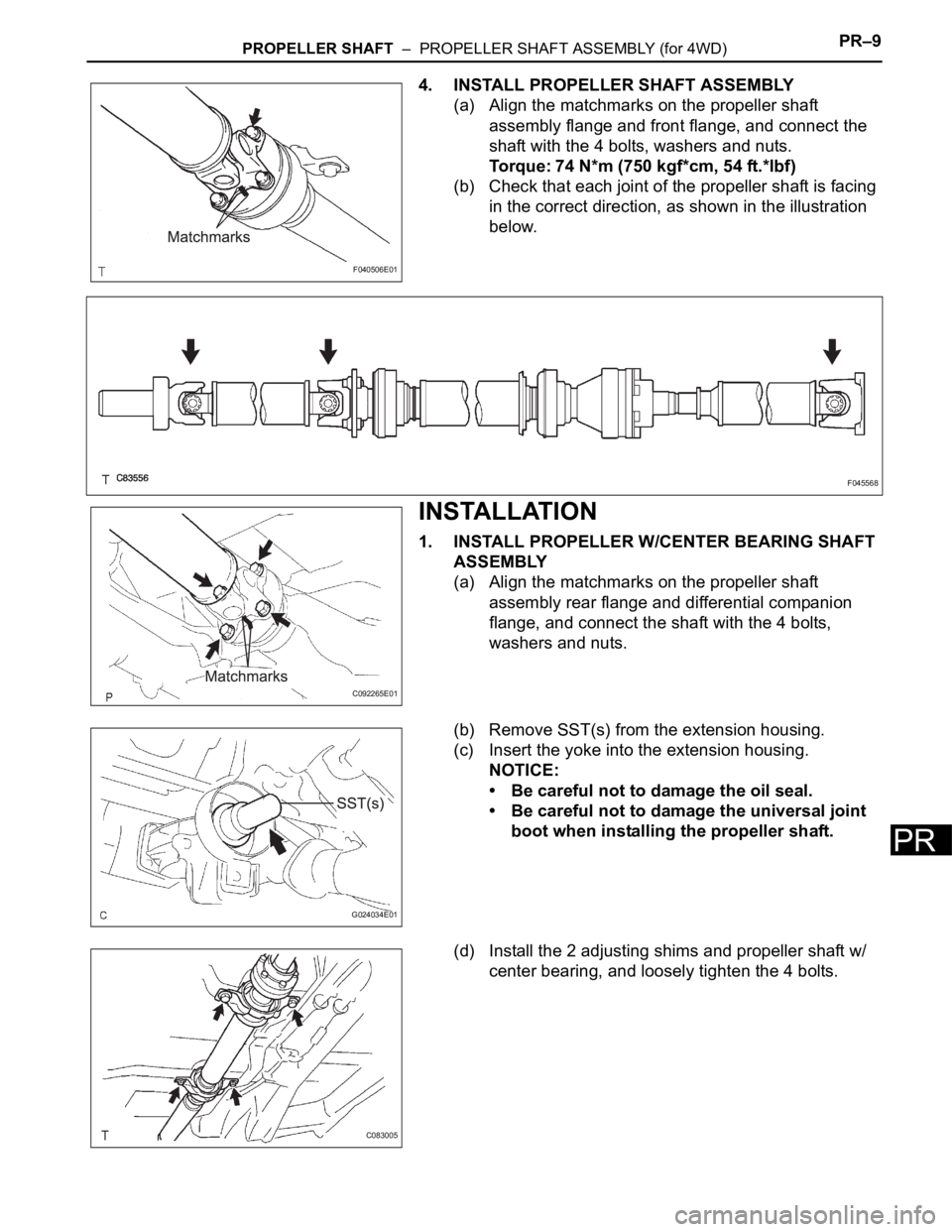
4. INSTALL PROPELLER SHAFT ASSEMBLY
(a) Align the matchmarks on the propeller shaft
assembly flange and front flange, and connect the
shaft with the 4 bolts, washers and nuts.
Torque: 74 N*m (750 kgf*cm, 54 ft.*lbf)
(b) Check that each joint of the propeller shaft is facing
in the correct direction, as shown in the illustration
below.
INSTALLATION
1. INSTALL PROPELLER W/CENTER BEARING SHAFT
ASSEMBLY
(a) Align the matchmarks on the propeller shaft
assembly rear flange and differential companion
flange, and connect the shaft with the 4 bolts,
washers and nuts.
(b) Remove SST(s) from the extension housing.
(c) Insert the yoke into the extension housing.
NOTICE:
• Be careful not to damage the oil seal.
• Be careful not to damage the universal joint
boot when installing the propeller shaft.
(d) Install the 2 adjusting shims and propeller shaft w/
center bearing, and loosely tighten the 4 bolts.
F040506E01
F045568
C092265E01
G024034E01
C083005