check oil TOYOTA SIENNA 2007 Service Repair Manual
[x] Cancel search | Manufacturer: TOYOTA, Model Year: 2007, Model line: SIENNA, Model: TOYOTA SIENNA 2007Pages: 3000, PDF Size: 52.26 MB
Page 2074 of 3000
DS–20DRIVE SHAFT – FRONT DRIVE SHAFT
DS
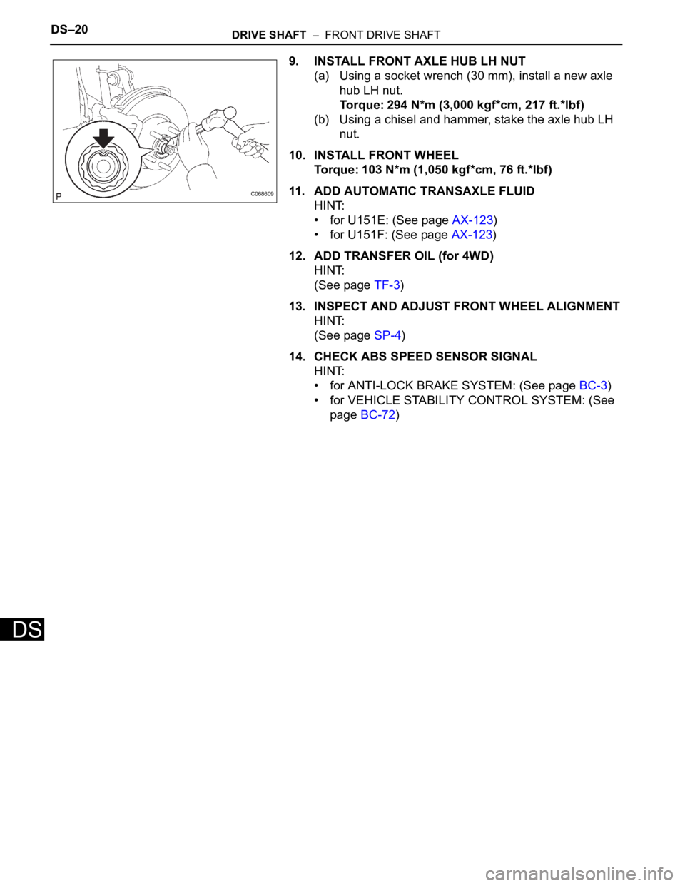
9. INSTALL FRONT AXLE HUB LH NUT
(a) Using a socket wrench (30 mm), install a new axle
hub LH nut.
Torque: 294 N*m (3,000 kgf*cm, 217 ft.*lbf)
(b) Using a chisel and hammer, stake the axle hub LH
nut.
10. INSTALL FRONT WHEEL
Torque: 103 N*m (1,050 kgf*cm, 76 ft.*lbf)
11. ADD AUTOMATIC TRANSAXLE FLUID
HINT:
• for U151E: (See page AX-123)
• for U151F: (See page AX-123)
12. ADD TRANSFER OIL (for 4WD)
HINT:
(See page TF-3)
13. INSPECT AND ADJUST FRONT WHEEL ALIGNMENT
HINT:
(See page SP-4)
14. CHECK ABS SPEED SENSOR SIGNAL
HINT:
• for ANTI-LOCK BRAKE SYSTEM: (See page BC-3)
• for VEHICLE STABILITY CONTROL SYSTEM: (See
page BC-72)
C068609
Page 2095 of 3000
DS–20DRIVE SHAFT – FRONT DRIVE SHAFT
DS
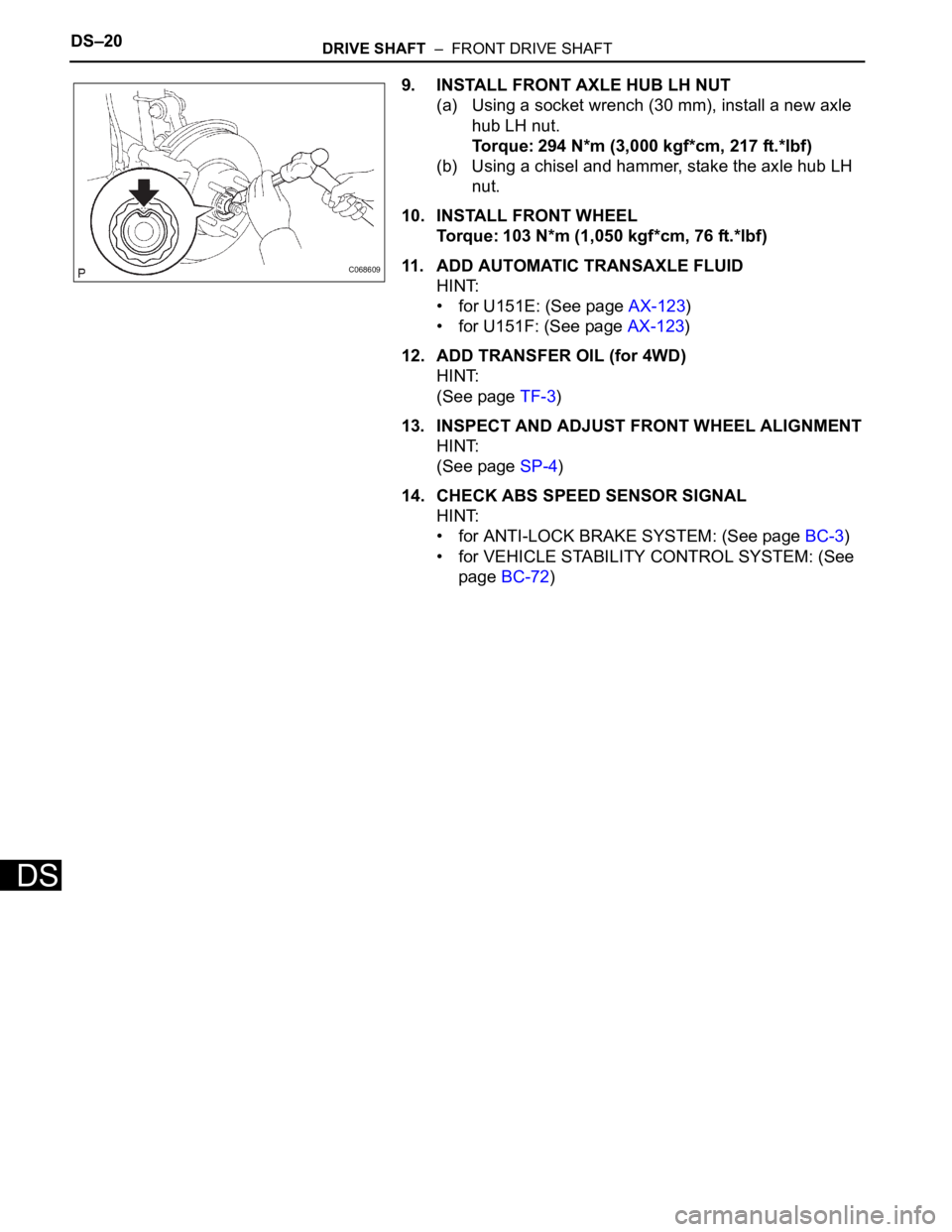
9. INSTALL FRONT AXLE HUB LH NUT
(a) Using a socket wrench (30 mm), install a new axle
hub LH nut.
Torque: 294 N*m (3,000 kgf*cm, 217 ft.*lbf)
(b) Using a chisel and hammer, stake the axle hub LH
nut.
10. INSTALL FRONT WHEEL
Torque: 103 N*m (1,050 kgf*cm, 76 ft.*lbf)
11. ADD AUTOMATIC TRANSAXLE FLUID
HINT:
• for U151E: (See page AX-123)
• for U151F: (See page AX-123)
12. ADD TRANSFER OIL (for 4WD)
HINT:
(See page TF-3)
13. INSPECT AND ADJUST FRONT WHEEL ALIGNMENT
HINT:
(See page SP-4)
14. CHECK ABS SPEED SENSOR SIGNAL
HINT:
• for ANTI-LOCK BRAKE SYSTEM: (See page BC-3)
• for VEHICLE STABILITY CONTROL SYSTEM: (See
page BC-72)
C068609
Page 2096 of 3000
DRIVE SHAFT – REAR DRIVE SHAFT (for 4WD)DS–27
DS
INSTALLATION
1. INSTALL REAR DRIVE SHAFT ASSEMBLY LH
(a) Install the drive shaft to the axle carrier.
NOTICE:
Be careful not to damage the boot and ABS
speed sensor rotor to the drive shaft and oil seal
of the axle hub bearing.
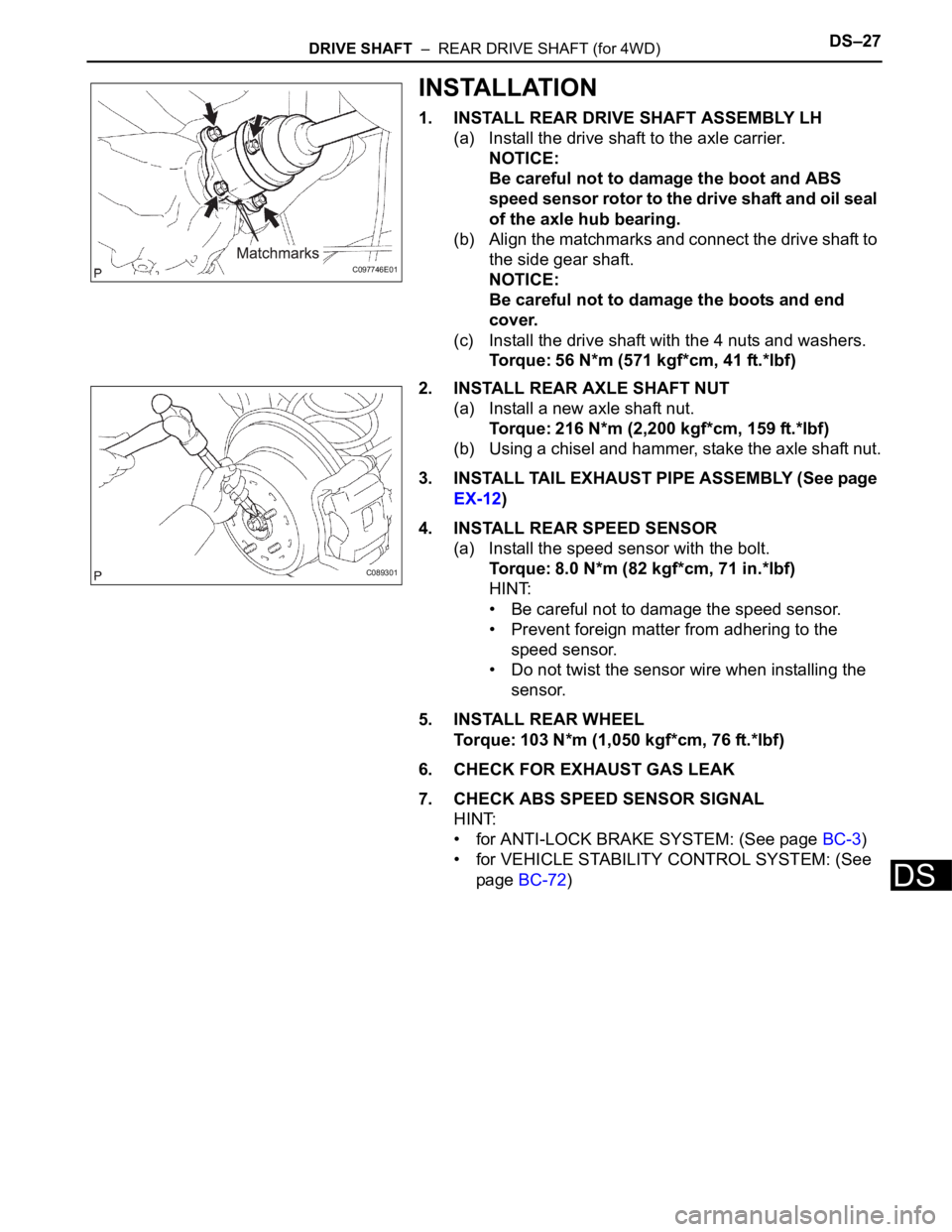
(b) Align the matchmarks and connect the drive shaft to
the side gear shaft.
NOTICE:
Be careful not to damage the boots and end
cover.
(c) Install the drive shaft with the 4 nuts and washers.
Torque: 56 N*m (571 kgf*cm, 41 ft.*lbf)
2. INSTALL REAR AXLE SHAFT NUT
(a) Install a new axle shaft nut.
Torque: 216 N*m (2,200 kgf*cm, 159 ft.*lbf)
(b) Using a chisel and hammer, stake the axle shaft nut.
3. INSTALL TAIL EXHAUST PIPE ASSEMBLY (See page
EX-12)
4. INSTALL REAR SPEED SENSOR
(a) Install the speed sensor with the bolt.
Torque: 8.0 N*m (82 kgf*cm, 71 in.*lbf)
HINT:
• Be careful not to damage the speed sensor.
• Prevent foreign matter from adhering to the
speed sensor.
• Do not twist the sensor wire when installing the
sensor.
5. INSTALL REAR WHEEL
Torque: 103 N*m (1,050 kgf*cm, 76 ft.*lbf)
6. CHECK FOR EXHAUST GAS LEAK
7. CHECK ABS SPEED SENSOR SIGNAL
HINT:
• for ANTI-LOCK BRAKE SYSTEM: (See page BC-3)
• for VEHICLE STABILITY CONTROL SYSTEM: (See
page BC-72)
C097746E01
C089301
Page 2100 of 3000
DRIVE SHAFT – REAR DRIVE SHAFT (for 4WD)DS–27
DS
INSTALLATION
1. INSTALL REAR DRIVE SHAFT ASSEMBLY LH
(a) Install the drive shaft to the axle carrier.
NOTICE:
Be careful not to damage the boot and ABS
speed sensor rotor to the drive shaft and oil seal
of the axle hub bearing.
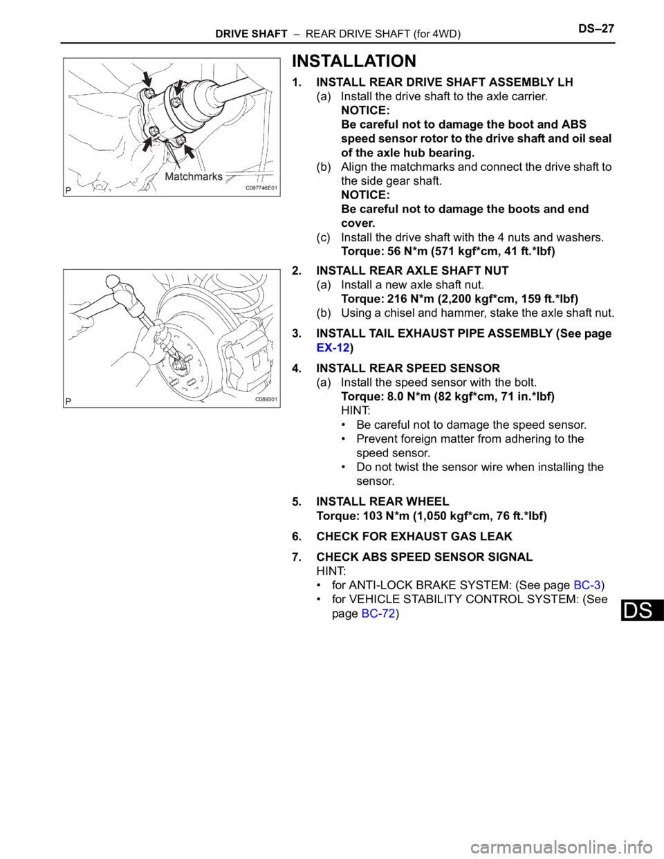
(b) Align the matchmarks and connect the drive shaft to
the side gear shaft.
NOTICE:
Be careful not to damage the boots and end
cover.
(c) Install the drive shaft with the 4 nuts and washers.
Torque: 56 N*m (571 kgf*cm, 41 ft.*lbf)
2. INSTALL REAR AXLE SHAFT NUT
(a) Install a new axle shaft nut.
Torque: 216 N*m (2,200 kgf*cm, 159 ft.*lbf)
(b) Using a chisel and hammer, stake the axle shaft nut.
3. INSTALL TAIL EXHAUST PIPE ASSEMBLY (See page
EX-12)
4. INSTALL REAR SPEED SENSOR
(a) Install the speed sensor with the bolt.
Torque: 8.0 N*m (82 kgf*cm, 71 in.*lbf)
HINT:
• Be careful not to damage the speed sensor.
• Prevent foreign matter from adhering to the
speed sensor.
• Do not twist the sensor wire when installing the
sensor.
5. INSTALL REAR WHEEL
Torque: 103 N*m (1,050 kgf*cm, 76 ft.*lbf)
6. CHECK FOR EXHAUST GAS LEAK
7. CHECK ABS SPEED SENSOR SIGNAL
HINT:
• for ANTI-LOCK BRAKE SYSTEM: (See page BC-3)
• for VEHICLE STABILITY CONTROL SYSTEM: (See
page BC-72)
C097746E01
C089301
Page 2114 of 3000
DF–16DIFFERENTIAL – REAR DIFFERENTIAL CARRIER
DF
DISASSEMBLY
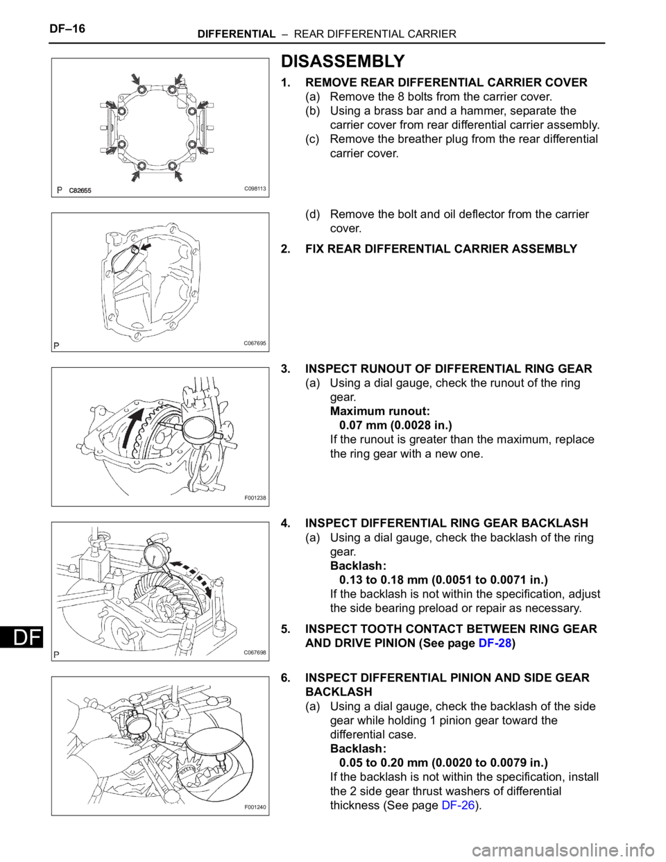
1. REMOVE REAR DIFFERENTIAL CARRIER COVER
(a) Remove the 8 bolts from the carrier cover.
(b) Using a brass bar and a hammer, separate the
carrier cover from rear differential carrier assembly.
(c) Remove the breather plug from the rear differential
carrier cover.
(d) Remove the bolt and oil deflector from the carrier
cover.
2. FIX REAR DIFFERENTIAL CARRIER ASSEMBLY
3. INSPECT RUNOUT OF DIFFERENTIAL RING GEAR
(a) Using a dial gauge, check the runout of the ring
gear.
Maximum runout:
0.07 mm (0.0028 in.)
If the runout is greater than the maximum, replace
the ring gear with a new one.
4. INSPECT DIFFERENTIAL RING GEAR BACKLASH
(a) Using a dial gauge, check the backlash of the ring
gear.
Backlash:
0.13 to 0.18 mm (0.0051 to 0.0071 in.)
If the backlash is not within the specification, adjust
the side bearing preload or repair as necessary.
5. INSPECT TOOTH CONTACT BETWEEN RING GEAR
AND DRIVE PINION (See page DF-28)
6. INSPECT DIFFERENTIAL PINION AND SIDE GEAR
BACKLASH
(a) Using a dial gauge, check the backlash of the side
gear while holding 1 pinion gear toward the
differential case.
Backlash:
0.05 to 0.20 mm (0.0020 to 0.0079 in.)
If the backlash is not within the specification, install
the 2 side gear thrust washers of differential
thickness (See page DF-26).
C098113
C067695
F001238
C067698
F001240
Page 2130 of 3000
DF–32DIFFERENTIAL – REAR DIFFERENTIAL CARRIER
DF
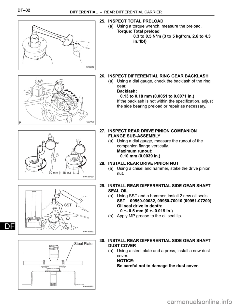
25. INSPECT TOTAL PRELOAD
(a) Using a torque wrench, measure the preload.
Torque: Total preload
0.3 to 0.5 N*m (3 to 5 kgf*cm, 2.6 to 4.3
in.*lbf)
26. INSPECT DIFFERENTIAL RING GEAR BACKLASH
(a) Using a dial gauge, check the backlash of the ring
gear.
Backlash:
0.13 to 0.18 mm (0.0051 to 0.0071 in.)
If the backlash is not within the specification, adjust
the side bearing preload or repair as necessary.
27. INSPECT REAR DRIVE PINION COMPANION
FLANGE SUB-ASSEMBLY
(a) Using a dial gauge, measure the runout of the
companion flange vertically.
Maximum runout:
0.10 mm (0.0039 in.)
28. INSTALL REAR DRIVE PINION NUT
(a) Using a chisel and hammer, stake the drive pinion
nut.
29. INSTALL REAR DIFFERENTIAL SIDE GEAR SHAFT
SEAL OIL
(a) Using SST and a hammer, install 2 new oil seals.
SST 09550-00032, 09950-70010 (09951-07200)
Oil seal drive in depth:
0 +- 0.5 mm (0 +- 0.019 in.)
(b) Apply MP grease to the oil seal lip.
30. INSTALL REAR DIFFERENTIAL SIDE GEAR SHAFT
DUST COVER
(a) Using a steel plate and a press, install a new dust
cover.
NOTICE:
Be careful not to damage the dust cover.
SA02352
G021129
F001237E01
F001262E02
F040465E01
Page 2133 of 3000
DIFFERENTIAL – DIFFERENTIAL OILDF–3
DF
DIFFERENTIAL OIL
ADJUSTMENT
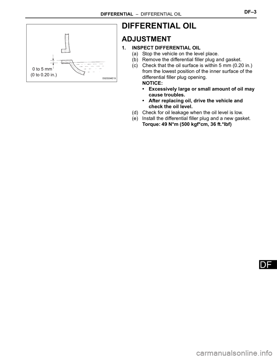
1. INSPECT DIFFERENTIAL OIL
(a) Stop the vehicle on the level place.
(b) Remove the differential filler plug and gasket.
(c) Check that the oil surface is within 5 mm (0.20 in.)
from the lowest position of the inner surface of the
differential filler plug opening.
NOTICE:
• Excessively large or small amount of oil may
cause troubles.
• After replacing oil, drive the vehicle and
check the oil level.
(d) Check for oil leakage when the oil level is low.
(e) Install the differential filler plug and a new gasket.
Torque: 49 N*m (500 kgf*cm, 36 ft.*lbf)
D025304E19
Page 2138 of 3000
DF–16DIFFERENTIAL – REAR DIFFERENTIAL CARRIER
DF
DISASSEMBLY
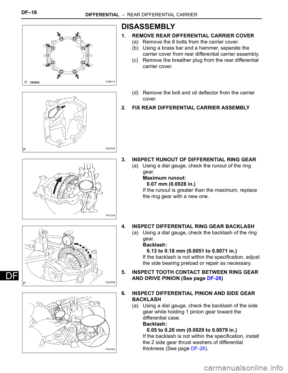
1. REMOVE REAR DIFFERENTIAL CARRIER COVER
(a) Remove the 8 bolts from the carrier cover.
(b) Using a brass bar and a hammer, separate the
carrier cover from rear differential carrier assembly.
(c) Remove the breather plug from the rear differential
carrier cover.
(d) Remove the bolt and oil deflector from the carrier
cover.
2. FIX REAR DIFFERENTIAL CARRIER ASSEMBLY
3. INSPECT RUNOUT OF DIFFERENTIAL RING GEAR
(a) Using a dial gauge, check the runout of the ring
gear.
Maximum runout:
0.07 mm (0.0028 in.)
If the runout is greater than the maximum, replace
the ring gear with a new one.
4. INSPECT DIFFERENTIAL RING GEAR BACKLASH
(a) Using a dial gauge, check the backlash of the ring
gear.
Backlash:
0.13 to 0.18 mm (0.0051 to 0.0071 in.)
If the backlash is not within the specification, adjust
the side bearing preload or repair as necessary.
5. INSPECT TOOTH CONTACT BETWEEN RING GEAR
AND DRIVE PINION (See page DF-28)
6. INSPECT DIFFERENTIAL PINION AND SIDE GEAR
BACKLASH
(a) Using a dial gauge, check the backlash of the side
gear while holding 1 pinion gear toward the
differential case.
Backlash:
0.05 to 0.20 mm (0.0020 to 0.0079 in.)
If the backlash is not within the specification, install
the 2 side gear thrust washers of differential
thickness (See page DF-26).
C098113
C067695
F001238
C067698
F001240
Page 2154 of 3000
DF–32DIFFERENTIAL – REAR DIFFERENTIAL CARRIER
DF
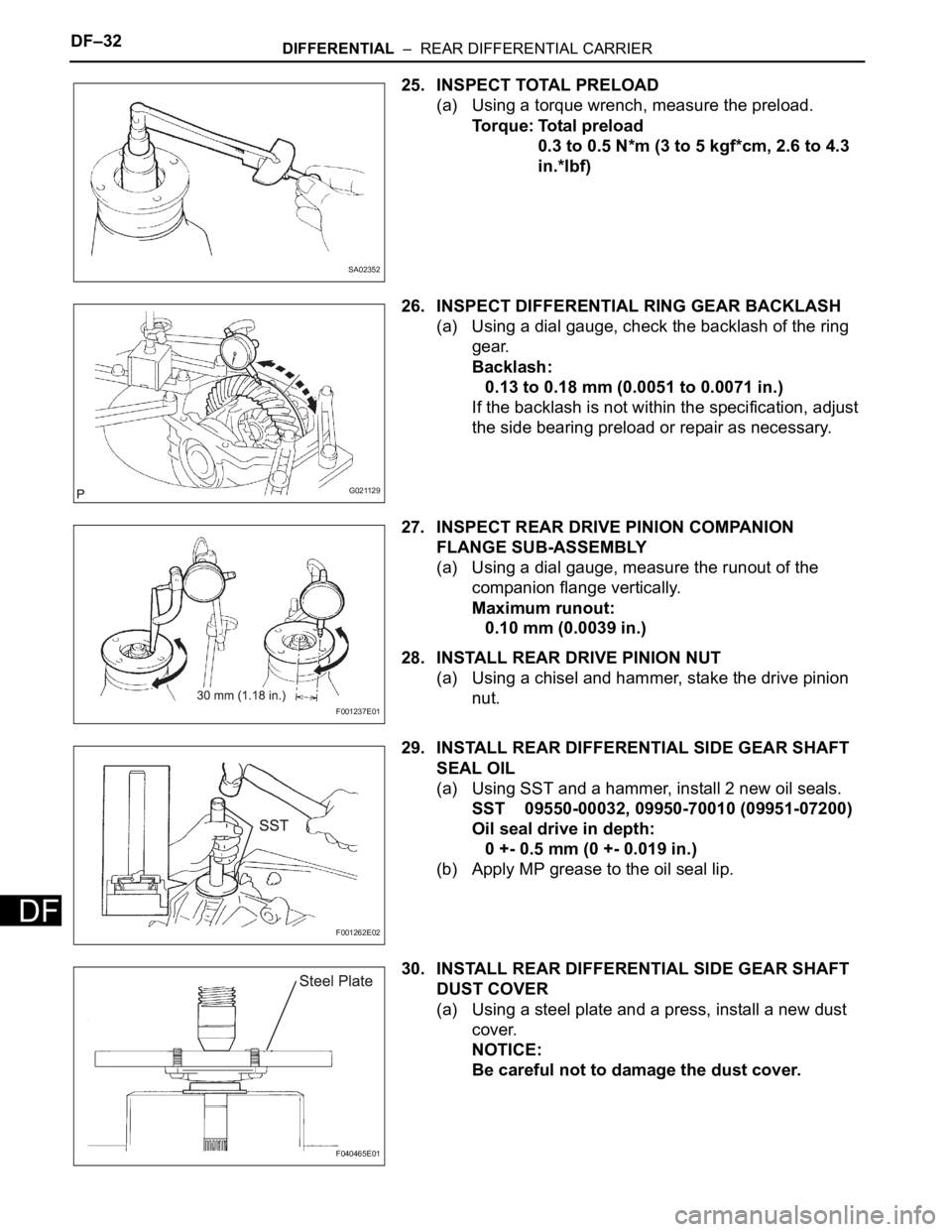
25. INSPECT TOTAL PRELOAD
(a) Using a torque wrench, measure the preload.
Torque: Total preload
0.3 to 0.5 N*m (3 to 5 kgf*cm, 2.6 to 4.3
in.*lbf)
26. INSPECT DIFFERENTIAL RING GEAR BACKLASH
(a) Using a dial gauge, check the backlash of the ring
gear.
Backlash:
0.13 to 0.18 mm (0.0051 to 0.0071 in.)
If the backlash is not within the specification, adjust
the side bearing preload or repair as necessary.
27. INSPECT REAR DRIVE PINION COMPANION
FLANGE SUB-ASSEMBLY
(a) Using a dial gauge, measure the runout of the
companion flange vertically.
Maximum runout:
0.10 mm (0.0039 in.)
28. INSTALL REAR DRIVE PINION NUT
(a) Using a chisel and hammer, stake the drive pinion
nut.
29. INSTALL REAR DIFFERENTIAL SIDE GEAR SHAFT
SEAL OIL
(a) Using SST and a hammer, install 2 new oil seals.
SST 09550-00032, 09950-70010 (09951-07200)
Oil seal drive in depth:
0 +- 0.5 mm (0 +- 0.019 in.)
(b) Apply MP grease to the oil seal lip.
30. INSTALL REAR DIFFERENTIAL SIDE GEAR SHAFT
DUST COVER
(a) Using a steel plate and a press, install a new dust
cover.
NOTICE:
Be careful not to damage the dust cover.
SA02352
G021129
F001237E01
F001262E02
F040465E01
Page 2180 of 3000
SUSPENSION – FRONT SHOCK ABSORBER WITH COIL SPRINGSP–15
SP
DISASSEMBLY
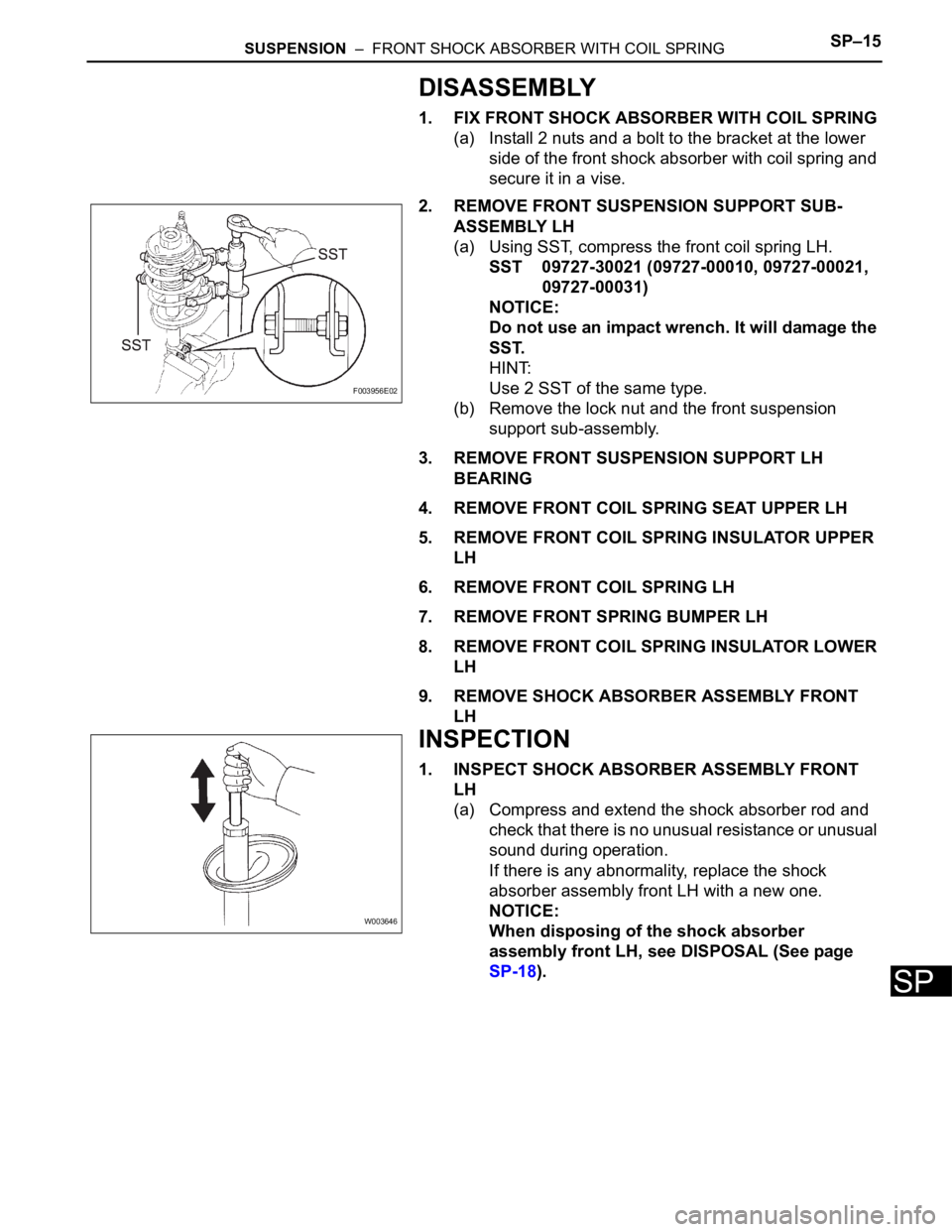
1. FIX FRONT SHOCK ABSORBER WITH COIL SPRING
(a) Install 2 nuts and a bolt to the bracket at the lower
side of the front shock absorber with coil spring and
secure it in a vise.
2. REMOVE FRONT SUSPENSION SUPPORT SUB-
ASSEMBLY LH
(a) Using SST, compress the front coil spring LH.
SST 09727-30021 (09727-00010, 09727-00021,
09727-00031)
NOTICE:
Do not use an impact wrench. It will damage the
SST.
HINT:
Use 2 SST of the same type.
(b) Remove the lock nut and the front suspension
support sub-assembly.
3. REMOVE FRONT SUSPENSION SUPPORT LH
BEARING
4. REMOVE FRONT COIL SPRING SEAT UPPER LH
5. REMOVE FRONT COIL SPRING INSULATOR UPPER
LH
6. REMOVE FRONT COIL SPRING LH
7. REMOVE FRONT SPRING BUMPER LH
8. REMOVE FRONT COIL SPRING INSULATOR LOWER
LH
9. REMOVE SHOCK ABSORBER ASSEMBLY FRONT
LH
INSPECTION
1. INSPECT SHOCK ABSORBER ASSEMBLY FRONT
LH
(a) Compress and extend the shock absorber rod and
check that there is no unusual resistance or unusual
sound during operation.
If there is any abnormality, replace the shock
absorber assembly front LH with a new one.
NOTICE:
When disposing of the shock absorber
assembly front LH, see DISPOSAL (See page
SP-18).
F003956E02
W003646