check oil TOYOTA SIENNA 2007 Service Repair Manual
[x] Cancel search | Manufacturer: TOYOTA, Model Year: 2007, Model line: SIENNA, Model: TOYOTA SIENNA 2007Pages: 3000, PDF Size: 52.26 MB
Page 1823 of 3000
U151F AUTOMATIC TRANSAXLE – VALVE BODY ASSEMBLYAX–137
AX
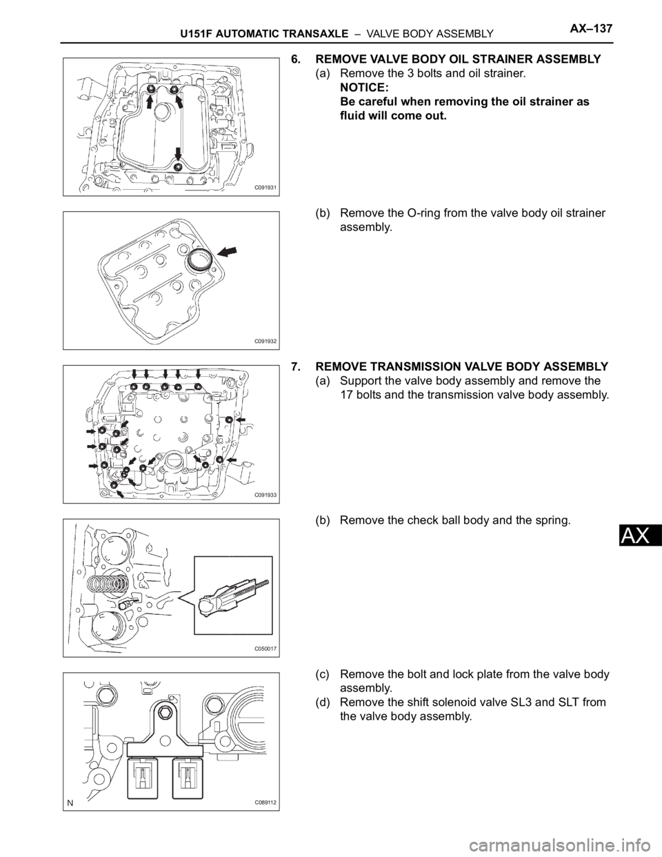
6. REMOVE VALVE BODY OIL STRAINER ASSEMBLY
(a) Remove the 3 bolts and oil strainer.
NOTICE:
Be careful when removing the oil strainer as
fluid will come out.
(b) Remove the O-ring from the valve body oil strainer
assembly.
7. REMOVE TRANSMISSION VALVE BODY ASSEMBLY
(a) Support the valve body assembly and remove the
17 bolts and the transmission valve body assembly.
(b) Remove the check ball body and the spring.
(c) Remove the bolt and lock plate from the valve body
assembly.
(d) Remove the shift solenoid valve SL3 and SLT from
the valve body assembly.
C091931
C091932
C091933
C050017
C089112
Page 1826 of 3000
AX–140U151F AUTOMATIC TRANSAXLE – VALVE BODY ASSEMBLY
AX
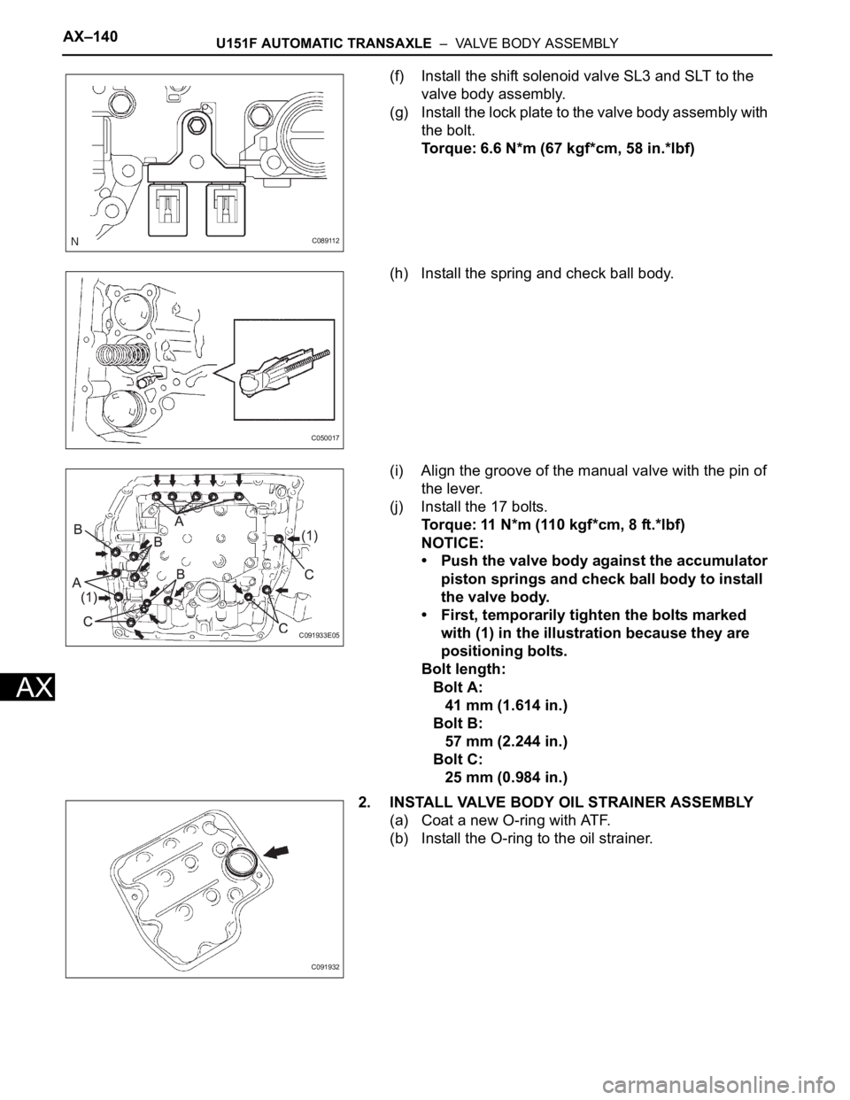
(f) Install the shift solenoid valve SL3 and SLT to the
valve body assembly.
(g) Install the lock plate to the valve body assembly with
the bolt.
Torque: 6.6 N*m (67 kgf*cm, 58 in.*lbf)
(h) Install the spring and check ball body.
(i) Align the groove of the manual valve with the pin of
the lever.
(j) Install the 17 bolts.
Torque: 11 N*m (110 kgf*cm, 8 ft.*lbf)
NOTICE:
• Push the valve body against the accumulator
piston springs and check ball body to install
the valve body.
• First, temporarily tighten the bolts marked
with (1) in the illustration because they are
positioning bolts.
Bolt length:
Bolt A:
41 mm (1.614 in.)
Bolt B:
57 mm (2.244 in.)
Bolt C:
25 mm (0.984 in.)
2. INSTALL VALVE BODY OIL STRAINER ASSEMBLY
(a) Coat a new O-ring with ATF.
(b) Install the O-ring to the oil strainer.
C089112
C050017
C091933E05
C091932
Page 1827 of 3000
U151F AUTOMATIC TRANSAXLE – VALVE BODY ASSEMBLYAX–141
AX
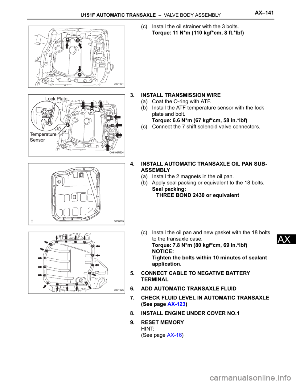
(c) Install the oil strainer with the 3 bolts.
Torque: 11 N*m (110 kgf*cm, 8 ft.*lbf)
3. INSTALL TRANSMISSION WIRE
(a) Coat the O-ring with ATF.
(b) Install the ATF temperature sensor with the lock
plate and bolt.
Torque: 6.6 N*m (67 kgf*cm, 58 in.*lbf)
(c) Connect the 7 shift solenoid valve connectors.
4. INSTALL AUTOMATIC TRANSAXLE OIL PAN SUB-
ASSEMBLY
(a) Install the 2 magnets in the oil pan.
(b) Apply seal packing or equivalent to the 18 bolts.
Seal packing:
THREE BOND 2430 or equivalent
(c) Install the oil pan and new gasket with the 18 bolts
to the transaxle case.
Torque: 7.8 N*m (80 kgf*cm, 69 in.*lbf)
NOTICE:
Tighten the bolts within 10 minutes of sealant
application.
5. CONNECT CABLE TO NEGATIVE BATTERY
TERMINAL
6. ADD AUTOMATIC TRANSAXLE FLUID
7. CHECK FLUID LEVEL IN AUTOMATIC TRANSAXLE
(See page AX-123)
8. INSTALL ENGINE UNDER COVER NO.1
9. RESET MEMORY
HINT:
(See page AX-16)
C091931
C091927E04
D030865
C091925
Page 1876 of 3000
U151F AUTOMATIC TRANSAXLE – AUTOMATIC TRANSAXLE UNITAX–201
AX
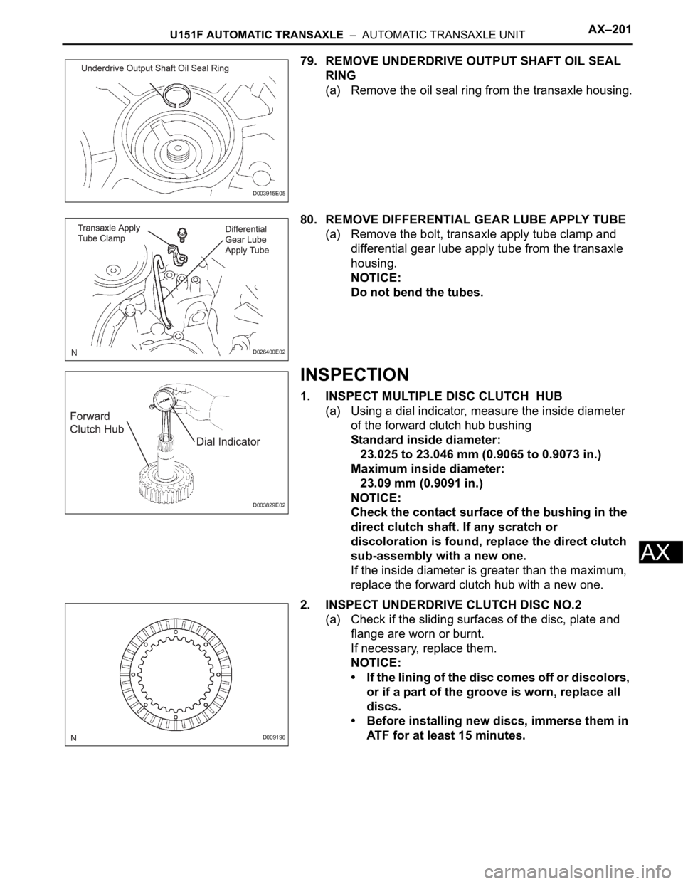
79. REMOVE UNDERDRIVE OUTPUT SHAFT OIL SEAL
RING
(a) Remove the oil seal ring from the transaxle housing.
80. REMOVE DIFFERENTIAL GEAR LUBE APPLY TUBE
(a) Remove the bolt, transaxle apply tube clamp and
differential gear lube apply tube from the transaxle
housing.
NOTICE:
Do not bend the tubes.
INSPECTION
1. INSPECT MULTIPLE DISC CLUTCH HUB
(a) Using a dial indicator, measure the inside diameter
of the forward clutch hub bushing
Standard inside diameter:
23.025 to 23.046 mm (0.9065 to 0.9073 in.)
Maximum inside diameter:
23.09 mm (0.9091 in.)
NOTICE:
Check the contact surface of the bushing in the
direct clutch shaft. If any scratch or
discoloration is found, replace the direct clutch
sub-assembly with a new one.
If the inside diameter is greater than the maximum,
replace the forward clutch hub with a new one.
2. INSPECT UNDERDRIVE CLUTCH DISC NO.2
(a) Check if the sliding surfaces of the disc, plate and
flange are worn or burnt.
If necessary, replace them.
NOTICE:
• If the lining of the disc comes off or discolors,
or if a part of the groove is worn, replace all
discs.
• Before installing new discs, immerse them in
ATF for at least 15 minutes.
D003915E05
D026400E02
D003829E02
D009196
Page 1915 of 3000
AX–232U151F AUTOMATIC TRANSAXLE – AUTOMATIC TRANSAXLE UNIT
AX
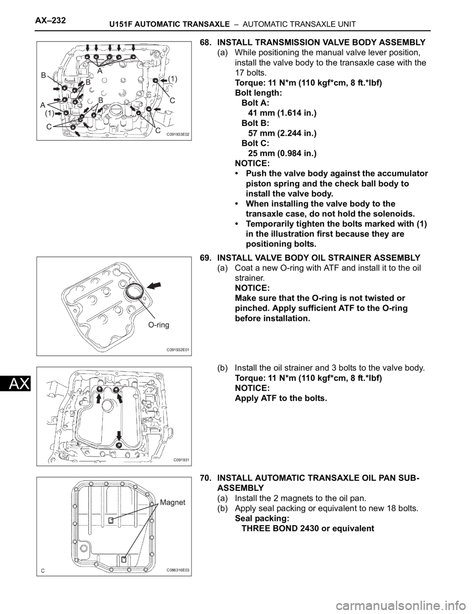
68. INSTALL TRANSMISSION VALVE BODY ASSEMBLY
(a) While positioning the manual valve lever position,
install the valve body to the transaxle case with the
17 bolts.
Torque: 11 N*m (110 kgf*cm, 8 ft.*lbf)
Bolt length:
Bolt A:
41 mm (1.614 in.)
Bolt B:
57 mm (2.244 in.)
Bolt C:
25 mm (0.984 in.)
NOTICE:
• Push the valve body against the accumulator
piston spring and the check ball body to
install the valve body.
• When installing the valve body to the
transaxle case, do not hold the solenoids.
• Temporarily tighten the bolts marked with (1)
in the illustration first because they are
positioning bolts.
69. INSTALL VALVE BODY OIL STRAINER ASSEMBLY
(a) Coat a new O-ring with ATF and install it to the oil
strainer.
NOTICE:
Make sure that the O-ring is not twisted or
pinched. Apply sufficient ATF to the O-ring
before installation.
(b) Install the oil strainer and 3 bolts to the valve body.
Torque: 11 N*m (110 kgf*cm, 8 ft.*lbf)
NOTICE:
Apply ATF to the bolts.
70. INSTALL AUTOMATIC TRANSAXLE OIL PAN SUB-
ASSEMBLY
(a) Install the 2 magnets to the oil pan.
(b) Apply seal packing or equivalent to new 18 bolts.
Seal packing:
THREE BOND 2430 or equivalent
C091933E02
C091932E01
C091931
C086316E03
Page 1920 of 3000
U151F AUTOMATIC TRANSAXLE – TORQUE CONVERTER CLUTCH AND DRIVE PLATEAX–173
AX
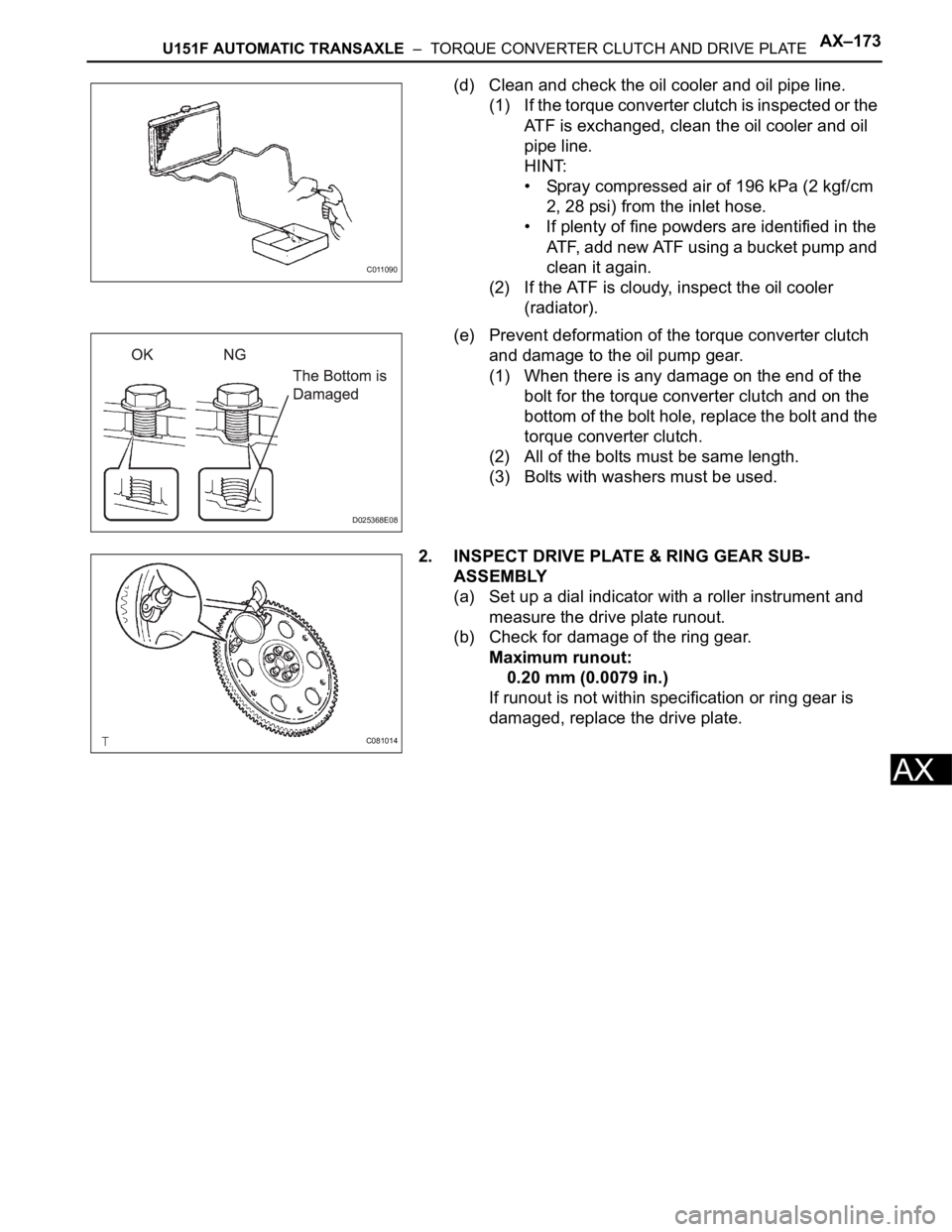
(d) Clean and check the oil cooler and oil pipe line.
(1) If the torque converter clutch is inspected or the
ATF is exchanged, clean the oil cooler and oil
pipe line.
HINT:
• Spray compressed air of 196 kPa (2 kgf/cm
2, 28 psi) from the inlet hose.
• If plenty of fine powders are identified in the
ATF, add new ATF using a bucket pump and
clean it again.
(2) If the ATF is cloudy, inspect the oil cooler
(radiator).
(e) Prevent deformation of the torque converter clutch
and damage to the oil pump gear.
(1) When there is any damage on the end of the
bolt for the torque converter clutch and on the
bottom of the bolt hole, replace the bolt and the
torque converter clutch.
(2) All of the bolts must be same length.
(3) Bolts with washers must be used.
2. INSPECT DRIVE PLATE & RING GEAR SUB-
ASSEMBLY
(a) Set up a dial indicator with a roller instrument and
measure the drive plate runout.
(b) Check for damage of the ring gear.
Maximum runout:
0.20 mm (0.0079 in.)
If runout is not within specification or ring gear is
damaged, replace the drive plate.
C011090
D025368E08
C081014
Page 1942 of 3000
U151F AUTOMATIC TRANSAXLE – AUTOMATIC TRANSAXLE UNITAX–201
AX
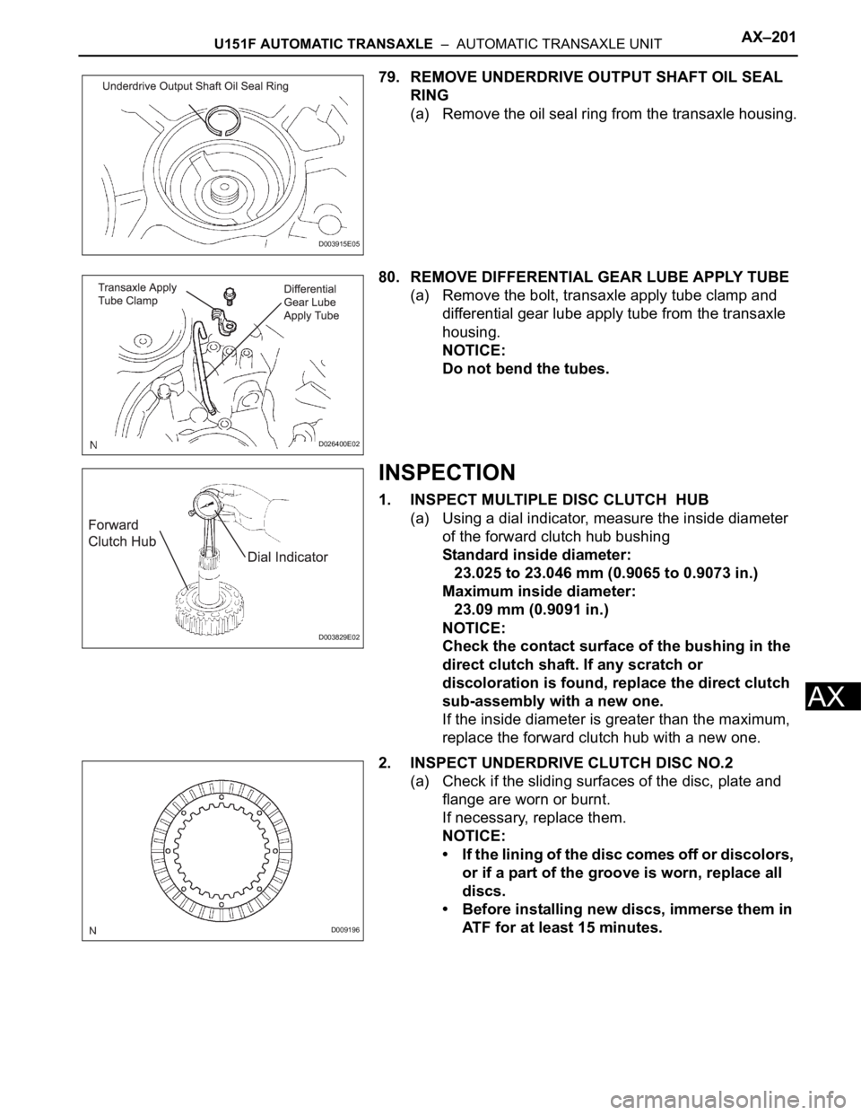
79. REMOVE UNDERDRIVE OUTPUT SHAFT OIL SEAL
RING
(a) Remove the oil seal ring from the transaxle housing.
80. REMOVE DIFFERENTIAL GEAR LUBE APPLY TUBE
(a) Remove the bolt, transaxle apply tube clamp and
differential gear lube apply tube from the transaxle
housing.
NOTICE:
Do not bend the tubes.
INSPECTION
1. INSPECT MULTIPLE DISC CLUTCH HUB
(a) Using a dial indicator, measure the inside diameter
of the forward clutch hub bushing
Standard inside diameter:
23.025 to 23.046 mm (0.9065 to 0.9073 in.)
Maximum inside diameter:
23.09 mm (0.9091 in.)
NOTICE:
Check the contact surface of the bushing in the
direct clutch shaft. If any scratch or
discoloration is found, replace the direct clutch
sub-assembly with a new one.
If the inside diameter is greater than the maximum,
replace the forward clutch hub with a new one.
2. INSPECT UNDERDRIVE CLUTCH DISC NO.2
(a) Check if the sliding surfaces of the disc, plate and
flange are worn or burnt.
If necessary, replace them.
NOTICE:
• If the lining of the disc comes off or discolors,
or if a part of the groove is worn, replace all
discs.
• Before installing new discs, immerse them in
ATF for at least 15 minutes.
D003915E05
D026400E02
D003829E02
D009196
Page 1953 of 3000
AX–248U151F AUTOMATIC TRANSAXLE – FORWARD CLUTCH
AX
REASSEMBLY
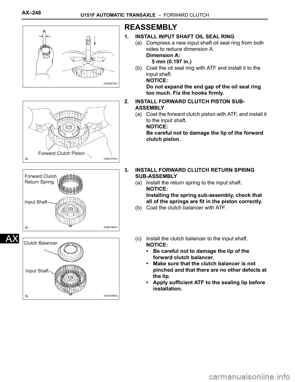
1. INSTALL INPUT SHAFT OIL SEAL RING
(a) Compress a new input shaft oil seal ring from both
sides to reduce dimension A.
Dimension A:
5 mm (0.197 in.)
(b) Coat the oil seal ring with ATF and install it to the
input shaft.
NOTICE:
Do not expand the end gap of the oil seal ring
too much. Fix the hooks firmly.
2. INSTALL FORWARD CLUTCH PISTON SUB-
ASSEMBLY
(a) Coat the forward clutch piston with ATF, and install it
to the input shaft.
NOTICE:
Be careful not to damage the lip of the forward
clutch piston.
3. INSTALL FORWARD CLUTCH RETURN SPRING
SUB-ASSEMBLY
(a) Install the return spring to the input shaft.
NOTICE:
Installing the spring sub-assembly, check that
all of the springs are fit in the piston correctly.
(b) Coat the clutch balancer with ATF.
(c) Install the clutch balancer to the input shaft.
NOTICE:
• Be careful not to damage the lip of the
forward clutch balancer.
• Make sure that the clutch balancer is not
pinched and that there are no other defects at
the lip.
• Apply sufficient ATF to the sealing lip before
installation.
D025587E01
D026707E01
D026708E01
D026709E02
Page 2014 of 3000
TF–24TRANSFER – TRANSFER UNIT
TF
(d) If the preload is insufficient, even though the
tightening torque of the transfer gear nut exceeds
the maximum of the standard value., loosen the
transfer gear nut and apply gear oil SAE 90 (GL-5)
to the transfer gear nut and the screw thread and
the base of driven pinion. And then repeat the
preceding operation . If the tightening torque is
bearing spacer with anew one and adjust it.
Torque: 378 N*m (3.855 kgf*cm, 279 ft.*lbf)
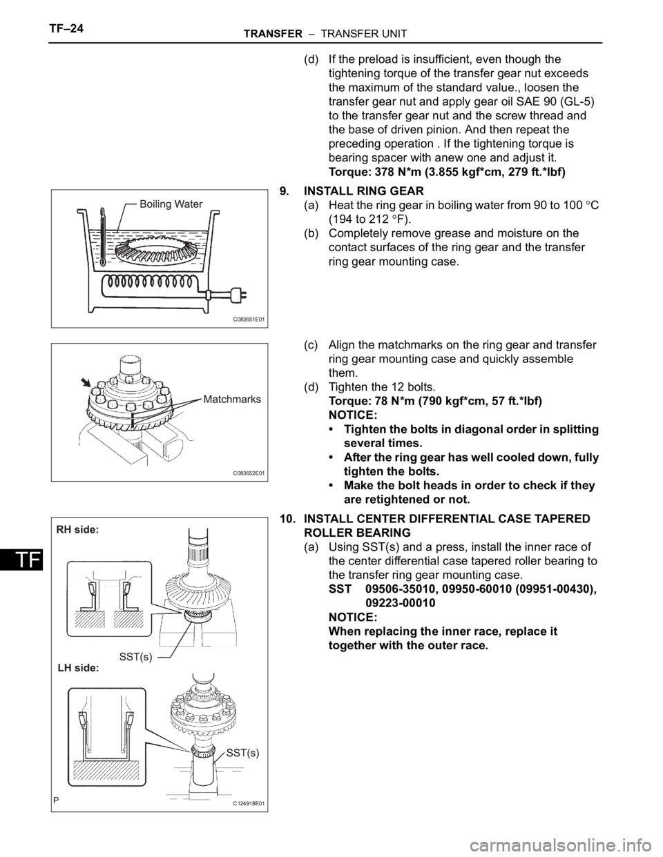
9. INSTALL RING GEAR
(a) Heat the ring gear in boiling water from 90 to 100
C
(194 to 212
F).
(b) Completely remove grease and moisture on the
contact surfaces of the ring gear and the transfer
ring gear mounting case.
(c) Align the matchmarks on the ring gear and transfer
ring gear mounting case and quickly assemble
them.
(d) Tighten the 12 bolts.
Torque: 78 N*m (790 kgf*cm, 57 ft.*lbf)
NOTICE:
• Tighten the bolts in diagonal order in splitting
several times.
• After the ring gear has well cooled down, fully
tighten the bolts.
• Make the bolt heads in order to check if they
are retightened or not.
10. INSTALL CENTER DIFFERENTIAL CASE TAPERED
ROLLER BEARING
(a) Using SST(s) and a press, install the inner race of
the center differential case tapered roller bearing to
the transfer ring gear mounting case.
SST 09506-35010, 09950-60010 (09951-00430),
09223-00010
NOTICE:
When replacing the inner race, replace it
together with the outer race.
C083651E01
C083652E01
C124918E01
Page 2021 of 3000
TRANSFER – TRANSFER UNITTF–31
TF
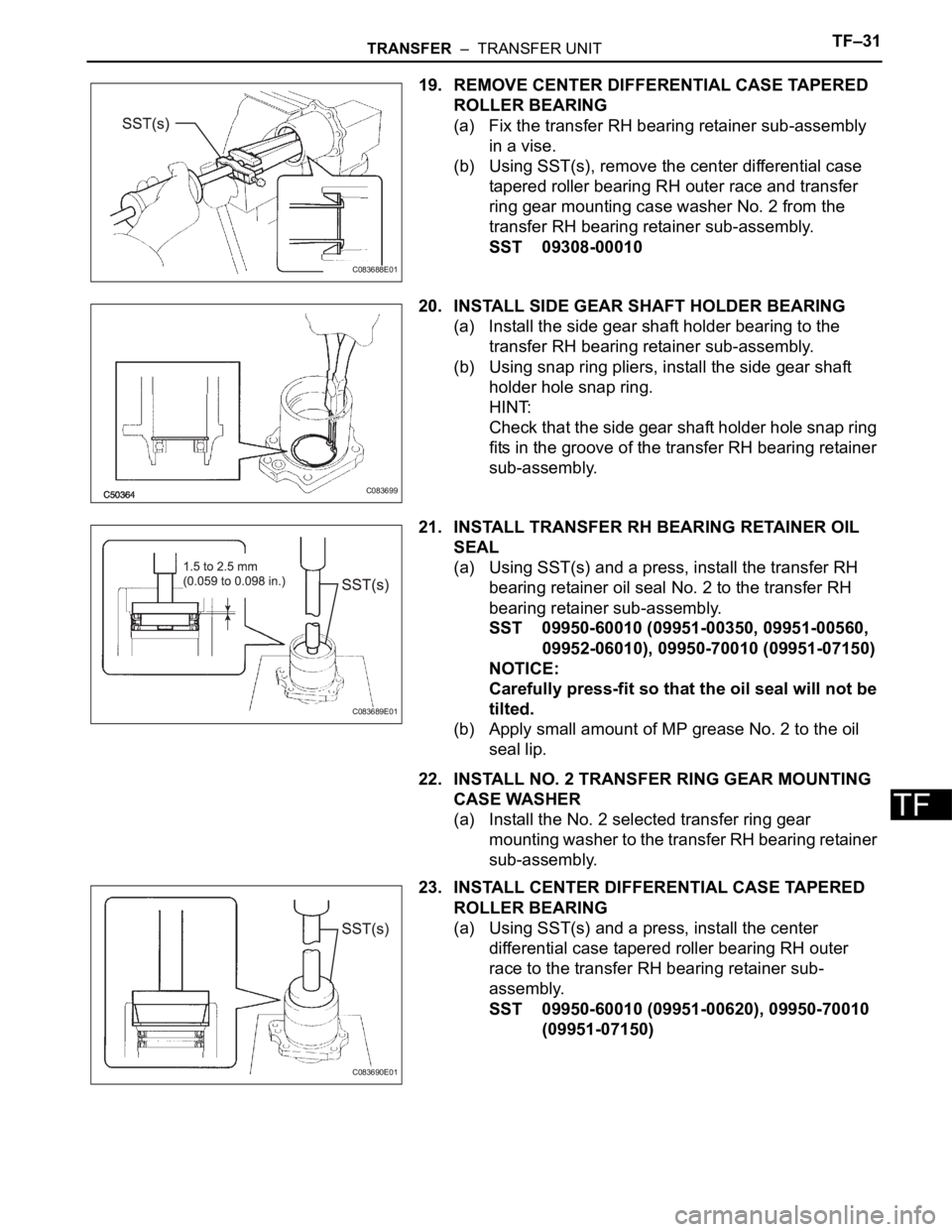
19. REMOVE CENTER DIFFERENTIAL CASE TAPERED
ROLLER BEARING
(a) Fix the transfer RH bearing retainer sub-assembly
in a vise.
(b) Using SST(s), remove the center differential case
tapered roller bearing RH outer race and transfer
ring gear mounting case washer No. 2 from the
transfer RH bearing retainer sub-assembly.
SST 09308-00010
20. INSTALL SIDE GEAR SHAFT HOLDER BEARING
(a) Install the side gear shaft holder bearing to the
transfer RH bearing retainer sub-assembly.
(b) Using snap ring pliers, install the side gear shaft
holder hole snap ring.
HINT:
Check that the side gear shaft holder hole snap ring
fits in the groove of the transfer RH bearing retainer
sub-assembly.
21. INSTALL TRANSFER RH BEARING RETAINER OIL
SEAL
(a) Using SST(s) and a press, install the transfer RH
bearing retainer oil seal No. 2 to the transfer RH
bearing retainer sub-assembly.
SST 09950-60010 (09951-00350, 09951-00560,
09952-06010), 09950-70010 (09951-07150)
NOTICE:
Carefully press-fit so that the oil seal will not be
tilted.
(b) Apply small amount of MP grease No. 2 to the oil
seal lip.
22. INSTALL NO. 2 TRANSFER RING GEAR MOUNTING
CASE WASHER
(a) Install the No. 2 selected transfer ring gear
mounting washer to the transfer RH bearing retainer
sub-assembly.
23. INSTALL CENTER DIFFERENTIAL CASE TAPERED
ROLLER BEARING
(a) Using SST(s) and a press, install the center
differential case tapered roller bearing RH outer
race to the transfer RH bearing retainer sub-
assembly.
SST 09950-60010 (09951-00620), 09950-70010
(09951-07150)
C083688E01
C083699
C083689E01
C083690E01