TOYOTA SIENNA 2007 Service Repair Manual
Manufacturer: TOYOTA, Model Year: 2007, Model line: SIENNA, Model: TOYOTA SIENNA 2007Pages: 3000, PDF Size: 52.26 MB
Page 2181 of 3000
SP–16SUSPENSION – FRONT SHOCK ABSORBER WITH COIL SPRING
SP
REASSEMBLY
1. INSTALL SHOCK ABSORBER ASSEMBLY FRONT LH
2. INSTALL FRONT COIL SPRING INSULATOR LOWER
LH
(a) Install the front coil spring insulator lower LH onto
the shock absorber assembly front LH.
3. INSTALL FRONT SPRING BUMPER LH
(a) Install the front spring bumper LH to the piston rod.
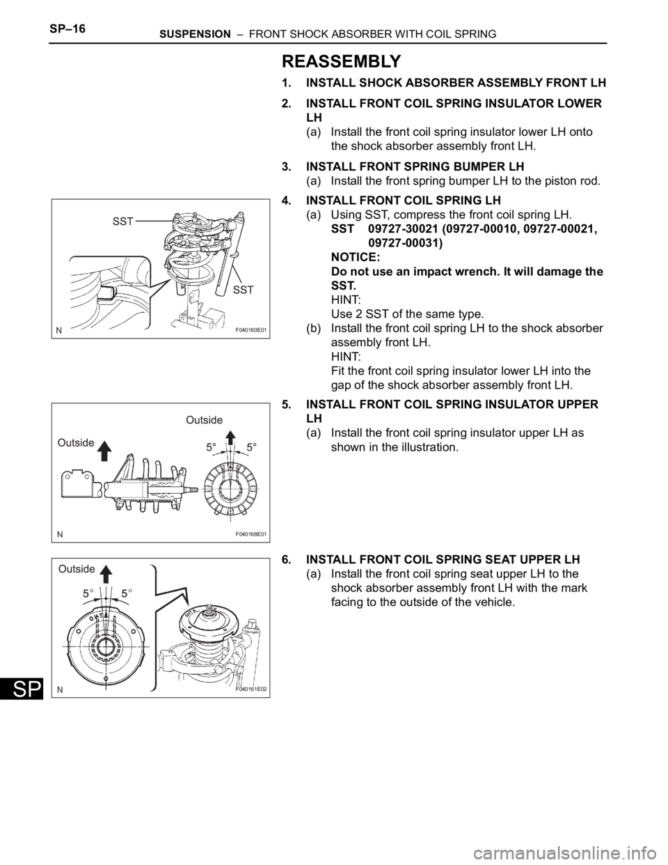
4. INSTALL FRONT COIL SPRING LH
(a) Using SST, compress the front coil spring LH.
SST 09727-30021 (09727-00010, 09727-00021,
09727-00031)
NOTICE:
Do not use an impact wrench. It will damage the
SST.
HINT:
Use 2 SST of the same type.
(b) Install the front coil spring LH to the shock absorber
assembly front LH.
HINT:
Fit the front coil spring insulator lower LH into the
gap of the shock absorber assembly front LH.
5. INSTALL FRONT COIL SPRING INSULATOR UPPER
LH
(a) Install the front coil spring insulator upper LH as
shown in the illustration.
6. INSTALL FRONT COIL SPRING SEAT UPPER LH
(a) Install the front coil spring seat upper LH to the
shock absorber assembly front LH with the mark
facing to the outside of the vehicle.
F040160E01
F040168E01
F040161E02
Page 2182 of 3000
SUSPENSION – FRONT SHOCK ABSORBER WITH COIL SPRINGSP–17
SP
7. INSTALL FRONT SUSPENSION SUPPORT LH
BEARING
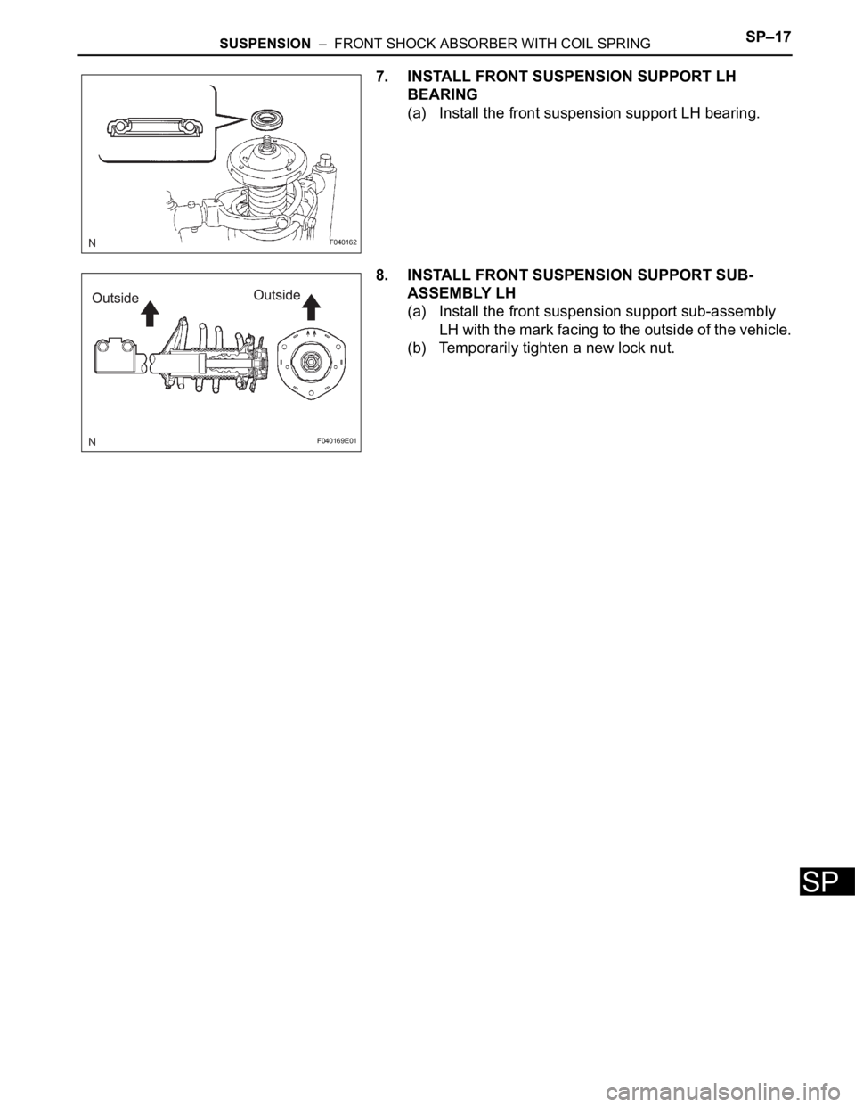
(a) Install the front suspension support LH bearing.
8. INSTALL FRONT SUSPENSION SUPPORT SUB-
ASSEMBLY LH
(a) Install the front suspension support sub-assembly
LH with the mark facing to the outside of the vehicle.
(b) Temporarily tighten a new lock nut.
F040162
F040169E01
Page 2183 of 3000
SP–18SUSPENSION – FRONT SHOCK ABSORBER WITH COIL SPRING
SP
INSTALLATION
1. INSTALL FRONT SHOCK ABSORBER WITH COIL
SPRING
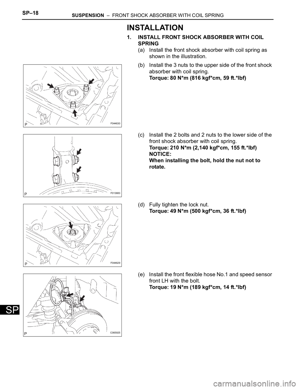
(a) Install the front shock absorber with coil spring as
shown in the illustration.
(b) Install the 3 nuts to the upper side of the front shock
absorber with coil spring.
Torque: 80 N*m (816 kgf*cm, 59 ft.*lbf)
(c) Install the 2 bolts and 2 nuts to the lower side of the
front shock absorber with coil spring.
Torque: 210 N*m (2,140 kgf*cm, 155 ft.*lbf)
NOTICE:
When installing the bolt, hold the nut not to
rotate.
(d) Fully tighten the lock nut.
Torque: 49 N*m (500 kgf*cm, 36 ft.*lbf)
(e) Install the front flexible hose No.1 and speed sensor
front LH with the bolt.
Torque: 19 N*m (189 kgf*cm, 14 ft.*lbf)
F044630
F013683
F044629
C065925
Page 2184 of 3000
SUSPENSION – FRONT SHOCK ABSORBER WITH COIL SPRINGSP–19
SP
2. INSTALL FRONT STABILIZER LINK ASSEMBLY LH
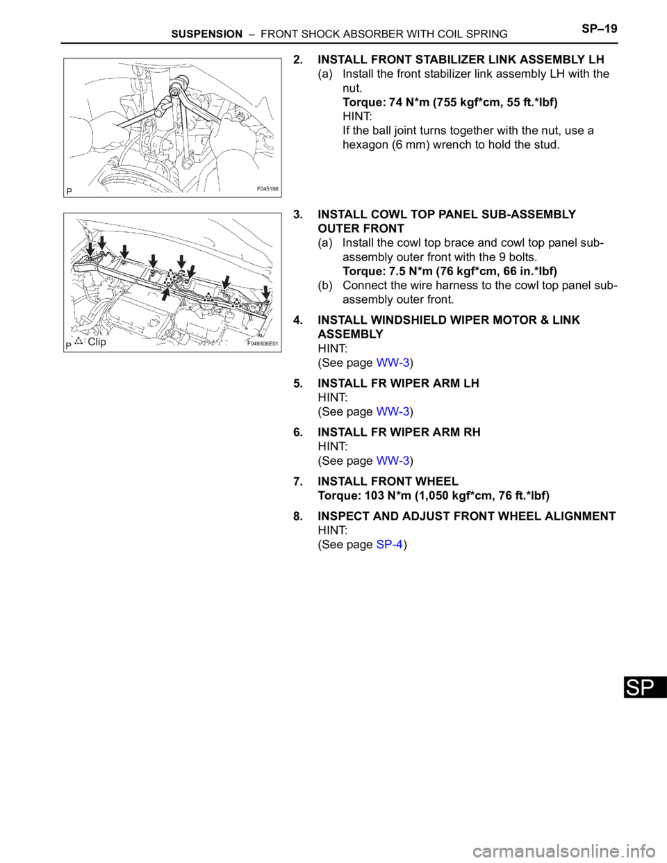
(a) Install the front stabilizer link assembly LH with the
nut.
Torque: 74 N*m (755 kgf*cm, 55 ft.*lbf)
HINT:
If the ball joint turns together with the nut, use a
hexagon (6 mm) wrench to hold the stud.
3. INSTALL COWL TOP PANEL SUB-ASSEMBLY
OUTER FRONT
(a) Install the cowl top brace and cowl top panel sub-
assembly outer front with the 9 bolts.
Torque: 7.5 N*m (76 kgf*cm, 66 in.*lbf)
(b) Connect the wire harness to the cowl top panel sub-
assembly outer front.
4. INSTALL WINDSHIELD WIPER MOTOR & LINK
ASSEMBLY
HINT:
(See page WW-3)
5. INSTALL FR WIPER ARM LH
HINT:
(See page WW-3)
6. INSTALL FR WIPER ARM RH
HINT:
(See page WW-3)
7. INSTALL FRONT WHEEL
Torque: 103 N*m (1,050 kgf*cm, 76 ft.*lbf)
8. INSPECT AND ADJUST FRONT WHEEL ALIGNMENT
HINT:
(See page SP-4)
F045196
F049306E01
Page 2185 of 3000
SP–20SUSPENSION – FRONT SHOCK ABSORBER WITH COIL SPRING
SP
DISPOSAL
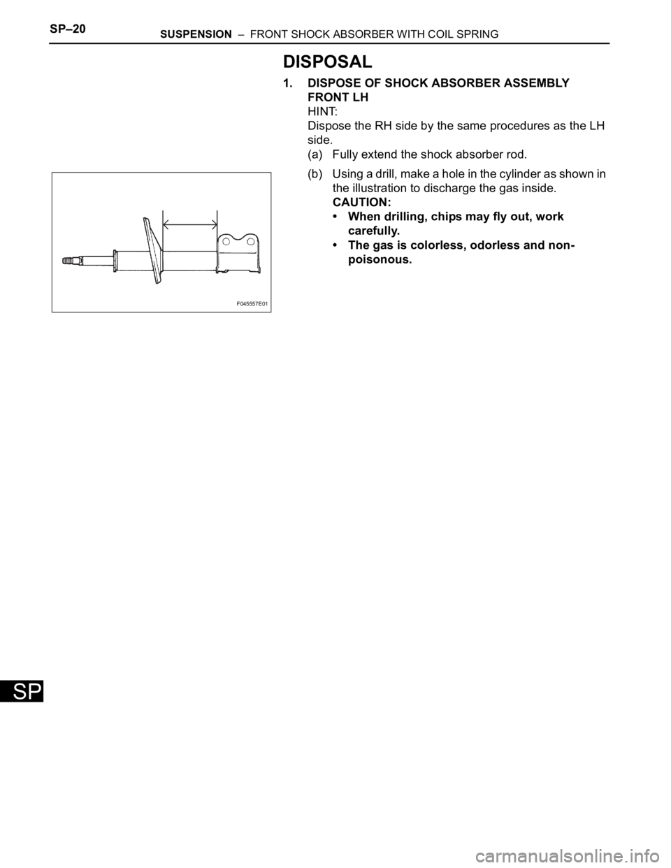
1. DISPOSE OF SHOCK ABSORBER ASSEMBLY
FRONT LH
HINT:
Dispose the RH side by the same procedures as the LH
side.
(a) Fully extend the shock absorber rod.
(b) Using a drill, make a hole in the cylinder as shown in
the illustration to discharge the gas inside.
CAUTION:
• When drilling, chips may fly out, work
carefully.
• The gas is colorless, odorless and non-
poisonous.
F045557E01
Page 2186 of 3000
SP–4SUSPENSION – FRONT WHEEL ALIGNMENT
SP
FRONT WHEEL ALIGNMENT
ADJUSTMENT
NOTICE:
For vehicles equipped with VSC, if wheel alignment has
been adjusted, and if suspension or underbody
components have been removed/installed or replaced, be
sure to perform the following initialization procedure in
order for the system to function normally:
1. Disconnect the negative battery terminal for more
than 2 seconds.
2. Reconnect the negative battery terminal.
3. Perform zero point calibration of the yaw rate and
acceleration sensor and test mode inspection.
HINT:
(See page BC-70)
1. INSPECT TIRE
HINT:
(See page TW-2)
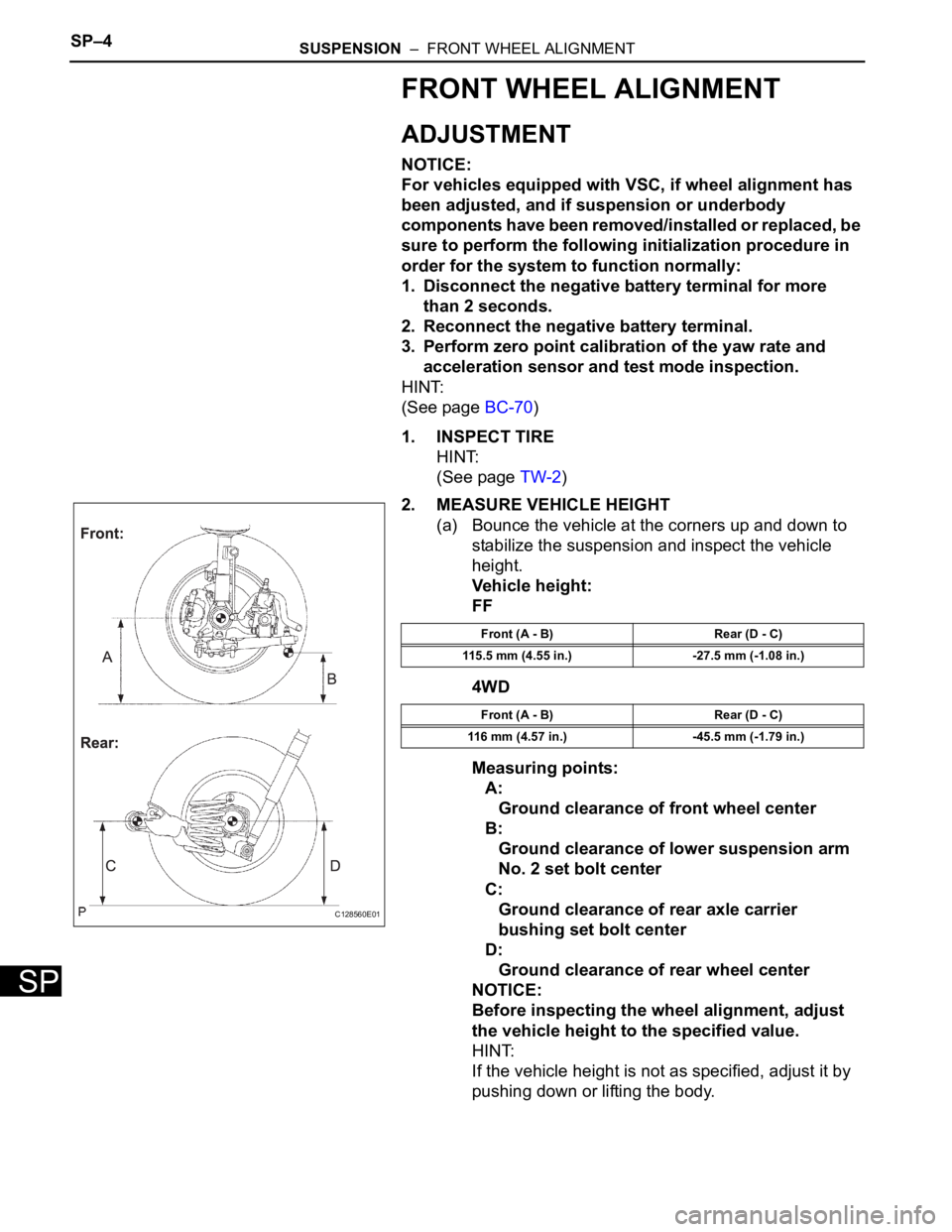
2. MEASURE VEHICLE HEIGHT
(a) Bounce the vehicle at the corners up and down to
stabilize the suspension and inspect the vehicle
height.
Vehicle height:
FF
4WD
Measuring points:
A:
Ground clearance of front wheel center
B:
Ground clearance of lower suspension arm
No. 2 set bolt center
C:
Ground clearance of rear axle carrier
bushing set bolt center
D:
Ground clearance of rear wheel center
NOTICE:
Before inspecting the wheel alignment, adjust
the vehicle height to the specified value.
HINT:
If the vehicle height is not as specified, adjust it by
pushing down or lifting the body.
C128560E01
Front (A - B) Rear (D - C)
115.5 mm (4.55 in.) -27.5 mm (-1.08 in.)
Front (A - B) Rear (D - C)
116 mm (4.57 in.) -45.5 mm (-1.79 in.)
Page 2187 of 3000
SUSPENSION – FRONT WHEEL ALIGNMENTSP–5
SP
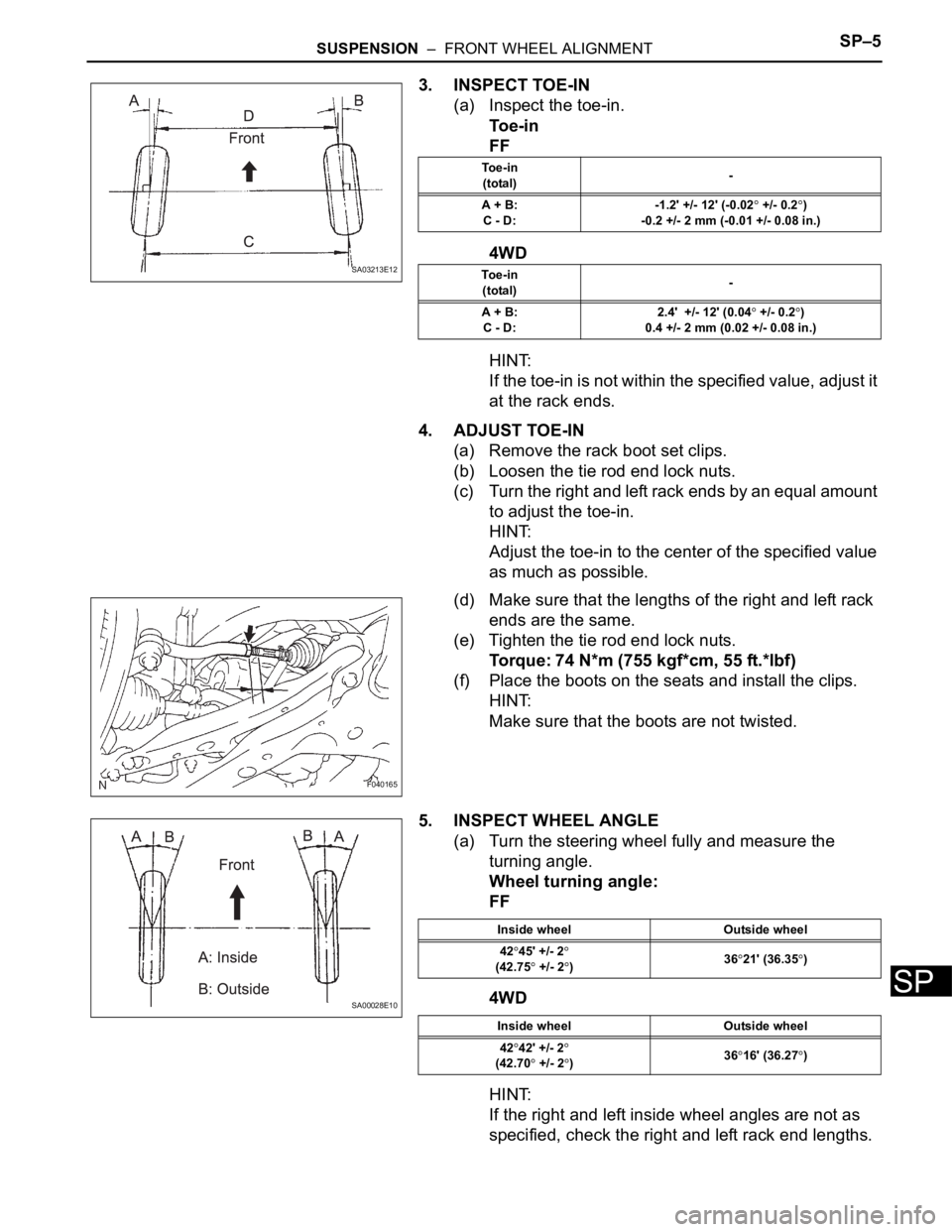
3. INSPECT TOE-IN
(a) Inspect the toe-in.
To e - i n
FF
4WD
HINT:
If the toe-in is not within the specified value, adjust it
at the rack ends.
4. ADJUST TOE-IN
(a) Remove the rack boot set clips.
(b) Loosen the tie rod end lock nuts.
(c) Turn the right and left rack ends by an equal amount
to adjust the toe-in.
HINT:
Adjust the toe-in to the center of the specified value
as much as possible.
(d) Make sure that the lengths of the right and left rack
ends are the same.
(e) Tighten the tie rod end lock nuts.
Torque: 74 N*m (755 kgf*cm, 55 ft.*lbf)
(f) Place the boots on the seats and install the clips.
HINT:
Make sure that the boots are not twisted.
5. INSPECT WHEEL ANGLE
(a) Turn the steering wheel fully and measure the
turning angle.
Wheel turning angle:
FF
4WD
HINT:
If the right and left inside wheel angles are not as
specified, check the right and left rack end lengths.
SA03213E12
To e - i n
(total)-
A + B:
C - D:-1.2' +/- 12' (-0.02
+/- 0.2)
-0.2 +/- 2 mm (-0.01 +/- 0.08 in.)
To e - i n
(total)-
A + B:
C - D:2.4' +/- 12' (0.04
+/- 0.2)
0.4 +/- 2 mm (0.02 +/- 0.08 in.)
F040165
SA00028E10
Inside wheel Outside wheel
42
45' +/- 2(42.75 +/- 2)3621' (36.35)
Inside wheel Outside wheel
42
42' +/- 2
(42.70 +/- 2)3616' (36.27)
Page 2188 of 3000
SP–6SUSPENSION – FRONT WHEEL ALIGNMENT
SP
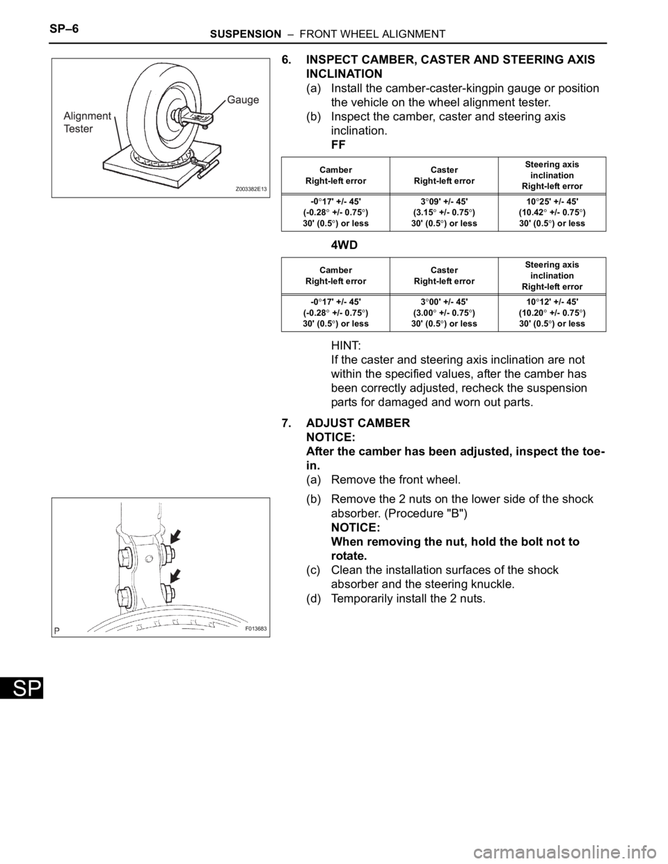
6. INSPECT CAMBER, CASTER AND STEERING AXIS
INCLINATION
(a) Install the camber-caster-kingpin gauge or position
the vehicle on the wheel alignment tester.
(b) Inspect the camber, caster and steering axis
inclination.
FF
4WD
HINT:
If the caster and steering axis inclination are not
within the specified values, after the camber has
been correctly adjusted, recheck the suspension
parts for damaged and worn out parts.
7. ADJUST CAMBER
NOTICE:
After the camber has been adjusted, inspect the toe-
in.
(a) Remove the front wheel.
(b) Remove the 2 nuts on the lower side of the shock
absorber. (Procedure "B")
NOTICE:
When removing the nut, hold the bolt not to
rotate.
(c) Clean the installation surfaces of the shock
absorber and the steering knuckle.
(d) Temporarily install the 2 nuts.
Z003382E13
Camber
Right-left errorCaster
Right-left errorSteering axis
inclination
Right-left error
-0
17' +/- 45'
(-0.28
+/- 0.75)
30' (0.5
) or less3
09' +/- 45'
(3.15
+/- 0.75)
30' (0.5
) or less10
25' +/- 45'
(10.42
+/- 0.75)
30' (0.5
) or less
Camber
Right-left errorCaster
Right-left errorSteering axis
inclination
Right-left error
-0
17' +/- 45'
(-0.28
+/- 0.75)
30' (0.5) or less3
00' +/- 45'
(3.00
+/- 0.75)
30' (0.5) or less10
12' +/- 45'
(10.20
+/- 0.75)
30' (0.5) or less
F013683
Page 2189 of 3000
SUSPENSION – FRONT WHEEL ALIGNMENTSP–7
SP
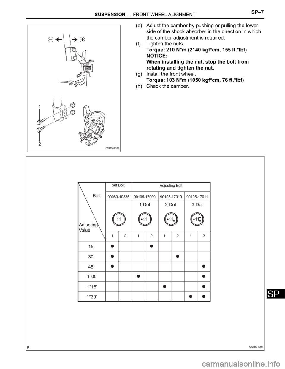
(e) Adjust the camber by pushing or pulling the lower
side of the shock absorber in the direction in which
the camber adjustment is required.
(f) Tighten the nuts.
Torque: 210 N*m (2140 kgf*cm, 155 ft.*lbf)
NOTICE:
When installing the nut, stop the bolt from
rotating and tighten the nut.
(g) Install the front wheel.
Torque: 103 N*m (1050 kgf*cm, 76 ft.*lbf)
(h) Check the camber.
C093869E02
C128571E01
Page 2190 of 3000

SP–8SUSPENSION – FRONT WHEEL ALIGNMENT
SP
HINT:
• Adjust the camber to the center of the specified
value as much as possible.
• Adjusting value for the set bolts is 6' to 30' (0.1
to 0.5
).
• If the camber is not within the specified value,
using the following table, estimate how much
additional camber adjustment will be required,
and select the camber adjusting bolt.
NOTICE:
Tighten the adjusting bolt with a washer and a
new nut.
(i) Perform the procedure mentioned above again. At
procedure "B", replace 1 or 2 selected bolts.
HINT:
Replace one bolt at a time when replacing 2 bolts.