TOYOTA SIENNA 2007 Service Repair Manual
Manufacturer: TOYOTA, Model Year: 2007, Model line: SIENNA, Model: TOYOTA SIENNA 2007Pages: 3000, PDF Size: 52.26 MB
Page 2171 of 3000
AH–16AXLE – REAR AXLE HUB AND BEARING (for 2WD)
AH
ON-VEHICLE INSPECTION
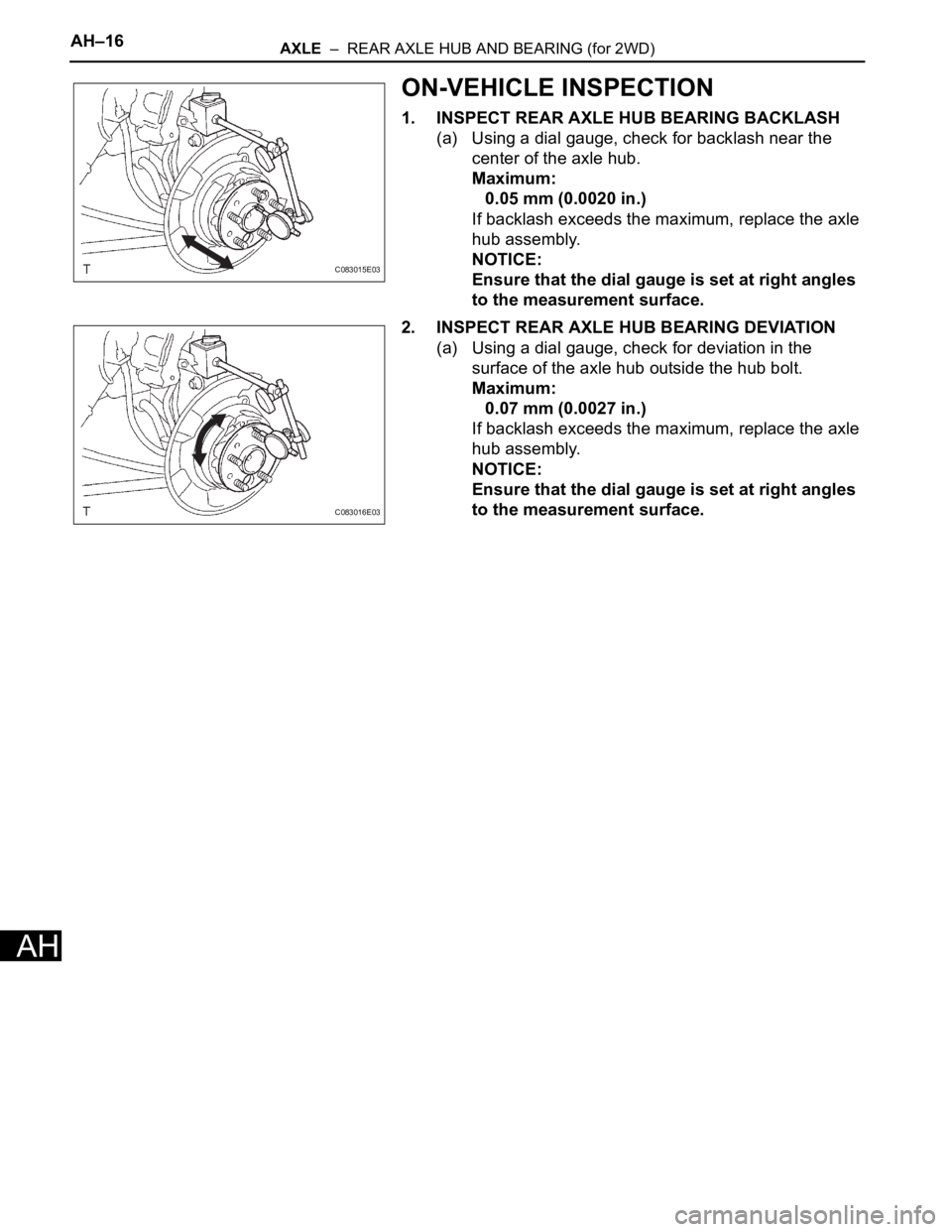
1. INSPECT REAR AXLE HUB BEARING BACKLASH
(a) Using a dial gauge, check for backlash near the
center of the axle hub.
Maximum:
0.05 mm (0.0020 in.)
If backlash exceeds the maximum, replace the axle
hub assembly.
NOTICE:
Ensure that the dial gauge is set at right angles
to the measurement surface.
2. INSPECT REAR AXLE HUB BEARING DEVIATION
(a) Using a dial gauge, check for deviation in the
surface of the axle hub outside the hub bolt.
Maximum:
0.07 mm (0.0027 in.)
If backlash exceeds the maximum, replace the axle
hub assembly.
NOTICE:
Ensure that the dial gauge is set at right angles
to the measurement surface.
C083015E03
C083016E03
Page 2172 of 3000
AXLE – REAR AXLE HUB AND BEARING (for 2WD)AH–17
AH
REMOVAL
HINT:
Replace the RH side by the same procedures as the LH side.
1. REMOVE REAR WHEEL
2. REMOVE REAR DISC BRAKE CALIPER ASSEMBLY
LH
(a) Removing the 2 bolts, separate the rear disc brake
caliper assembly LH for disc rear brake type.
NOTICE:
Using a string and so on, hang down the disc
brake caliper.
3. REMOVE REAR DISC
(a) Remove rear disc for disc rear brake type.
4. REMOVE REAR BRAKE DRUM SUB-ASSEMBLY
(a) Remove rear brake drum sub-assembly for drum
rear brake type.
5. SEPARATE SKID CONTROL SENSOR WIRE
(a) Disconnect the connector
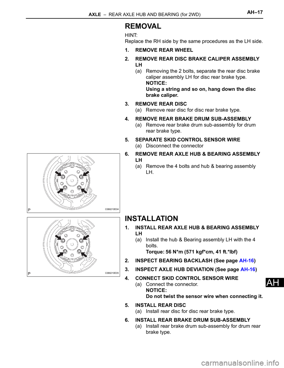
6. REMOVE REAR AXLE HUB & BEARING ASSEMBLY
LH
(a) Remove the 4 bolts and hub & bearing assembly
LH.
INSTALLATION
1. INSTALL REAR AXLE HUB & BEARING ASSEMBLY
LH
(a) Install the hub & Bearing assembly LH with the 4
bolts.
Torque: 56 N*m (571 kgf*cm, 41 ft.*lbf)
2. INSPECT BEARING BACKLASH (See page AH-16)
3. INSPECT AXLE HUB DEVIATION (See page AH-16)
4. CONNECT SKID CONTROL SENSOR WIRE
(a) Connect the connector.
NOTICE:
Do not twist the sensor wire when connecting it.
5. INSTALL REAR DISC
(a) Install rear disc for disc rear brake type.
6. INSTALL REAR BRAKE DRUM SUB-ASSEMBLY
(a) Install rear brake drum sub-assembly for drum rear
brake type.
C066210E04
C066210E05
Page 2173 of 3000
AH–18AXLE – REAR AXLE HUB AND BEARING (for 2WD)
AH
7. INSTALL REAR DISC BRAKE CALIPER ASSEMBLY
LH
(a) Install the rear disc brake caliper assembly LH with
the 2 bolts for disc rear brake type.
Torque: 88 N*m (900 kgf*cm, 65 ft.*lbf)
8. INSTALL REAR WHEEL
Torque: 103 N*m (1,050 kgf*cm, 76 ft.*lbf)
9. CHECK ABS SPEED SENSOR SIGNAL
(a) ABS WITH EBD SYSTEM (See page BC-3).
(b) ABS WITH EBD & BA & TRAC & VSC SYSTEM
(See page BC-72).
Page 2174 of 3000
AH–18AXLE – REAR AXLE HUB AND BEARING (for 4WD)
AH
SUSPENSION & AXLE
AXLE
REAR AXLE HUB AND BEARING (for 4WD)
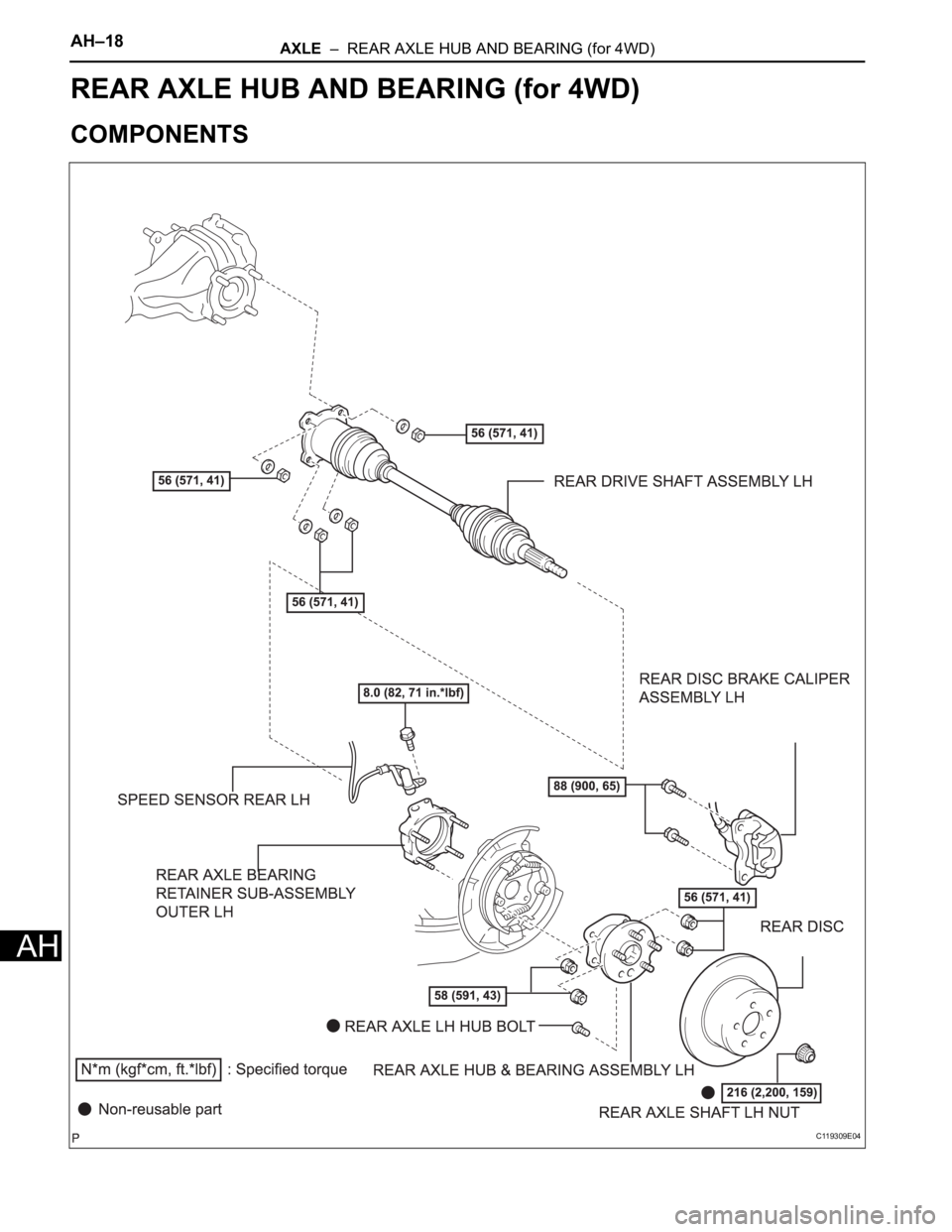
COMPONENTS
C119309E04
Page 2175 of 3000
AXLE – REAR AXLE HUB AND BEARING (for 4WD)AH–19
AH
ON-VEHICLE INSPECTION
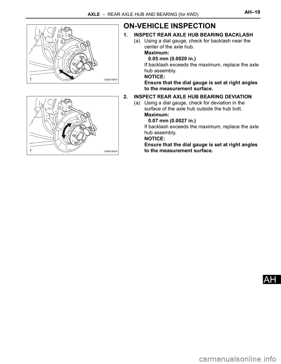
1. INSPECT REAR AXLE HUB BEARING BACKLASH
(a) Using a dial gauge, check for backlash near the
center of the axle hub.
Maximum:
0.05 mm (0.0020 in.)
If backlash exceeds the maximum, replace the axle
hub assembly.
NOTICE:
Ensure that the dial gauge is set at right angles
to the measurement surface.
2. INSPECT REAR AXLE HUB BEARING DEVIATION
(a) Using a dial gauge, check for deviation in the
surface of the axle hub outside the hub bolt.
Maximum:
0.07 mm (0.0027 in.)
If backlash exceeds the maximum, replace the axle
hub assembly.
NOTICE:
Ensure that the dial gauge is set at right angles
to the measurement surface.
C083015E04
C083016E04
Page 2176 of 3000
AH–20AXLE – REAR AXLE HUB AND BEARING (for 4WD)
AH
REMOVAL
HINT:
Replace the RH side by the same procedures as the LH side.
1. REMOVE REAR WHEEL
2. REMOVE REAR AXLE SHAFT LH NUT (See page DS-
22)
3. SEPARATE REAR DISC BRAKE CALIPER
ASSEMBLY LH
(a) Removing the 2 bolts, separate the rear disc brake
caliper assembly LH.
4. REMOVE REAR DISC
5. SEPARATE SPEED SENSOR REAR LH
(a) Removing the bolt, separate the speed sensor rear
LH.
NOTICE:
• Be careful not to damage the speed sensor.
• Prevent foreign matter from attaching to the
speed sensor.
6. REMOVE REAR DRIVE SHAFT ASSEMBLY LH (See
page DS-22)
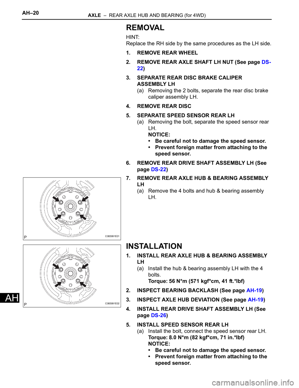
7. REMOVE REAR AXLE HUB & BEARING ASSEMBLY
LH
(a) Remove the 4 bolts and hub & bearing assembly
LH.
INSTALLATION
1. INSTALL REAR AXLE HUB & BEARING ASSEMBLY
LH
(a) Install the hub & bearing assembly LH with the 4
bolts.
Torque: 56 N*m (571 kgf*cm, 41 ft.*lbf)
2. INSPECT BEARING BACKLASH (See page AH-19)
3. INSPECT AXLE HUB DEVIATION (See page AH-19)
4. INSTALL REAR DRIVE SHAFT ASSEMBLY LH (See
page DS-26)
5. INSTALL SPEED SENSOR REAR LH
(a) Install the bolt, connect the speed sensor rear LH.
Torque: 8.0 N*m (82 kgf*cm, 71 in.*lbf)
NOTICE:
• Be careful not to damage the speed sensor.
• Prevent foreign matter from attaching to the
speed sensor.
C065991E01
C065991E02
Page 2177 of 3000
AXLE – REAR AXLE HUB AND BEARING (for 4WD)AH–21
AH
• Do not twist the sensor wire when installing
the sensor.
6. INSTALL REAR DISC
7. INSTALL REAR DISC BRAKE CALIPER ASSEMBLY
LH
(a) Install the rear disc brake caliper assembly LH with
the 2 bolts.
Torque: 88 N*m (900 kgf*cm, 65 ft.*lbf)
8. INSTALL REAR AXLE SHAFT LH NUT (See page DS-
26)
9. INSTALL REAR WHEEL
Torque: 103 N*m (1,050 kgf*cm, 76 ft.*lbf)
10. CHECK ABS SPEED SENSOR SIGNAL
(a) ABS WITH EBD & BA & TRAC & VSC SYSTEM
(See page BC-72).
Page 2178 of 3000
SUSPENSION – FRONT SHOCK ABSORBER WITH COIL SPRINGSP–13
SP
REMOVAL
1. REMOVE FRONT WHEEL
2. REMOVE FRONT WIPER ARM HEAD CAP
HINT:
(See page WW-3)
3. REMOVE FR WIPER ARM RH
HINT:
(See page WW-3)
4. REMOVE FR WIPER ARM LH
HINT:
(See page WW-3)
5. REMOVE COWL TOP VENTILATOR LOUVER SUB-
ASSEMBLY
HINT:
(See page WW-3)
6. REMOVE WINDSHIELD WIPER MOTOR & LINK
ASSEMBLY
HINT:
(See page WW-3)
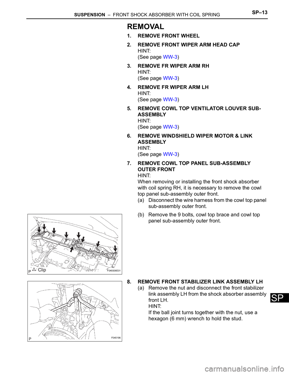
7. REMOVE COWL TOP PANEL SUB-ASSEMBLY
OUTER FRONT
HINT:
When removing or installing the front shock absorber
with coil spring RH, it is necessary to remove the cowl
top panel sub-assembly outer front.
(a) Disconnect the wire harness from the cowl top panel
sub-assembly outer front.
(b) Remove the 9 bolts, cowl top brace and cowl top
panel sub-assembly outer front.
8. REMOVE FRONT STABILIZER LINK ASSEMBLY LH
(a) Remove the nut and disconnect the front stabilizer
link assembly LH from the shock absorber assembly
front LH.
HINT:
If the ball joint turns together with the nut, use a
hexagon (6 mm) wrench to hold the stud.
F049306E01
F045196
Page 2179 of 3000
SP–14SUSPENSION – FRONT SHOCK ABSORBER WITH COIL SPRING
SP
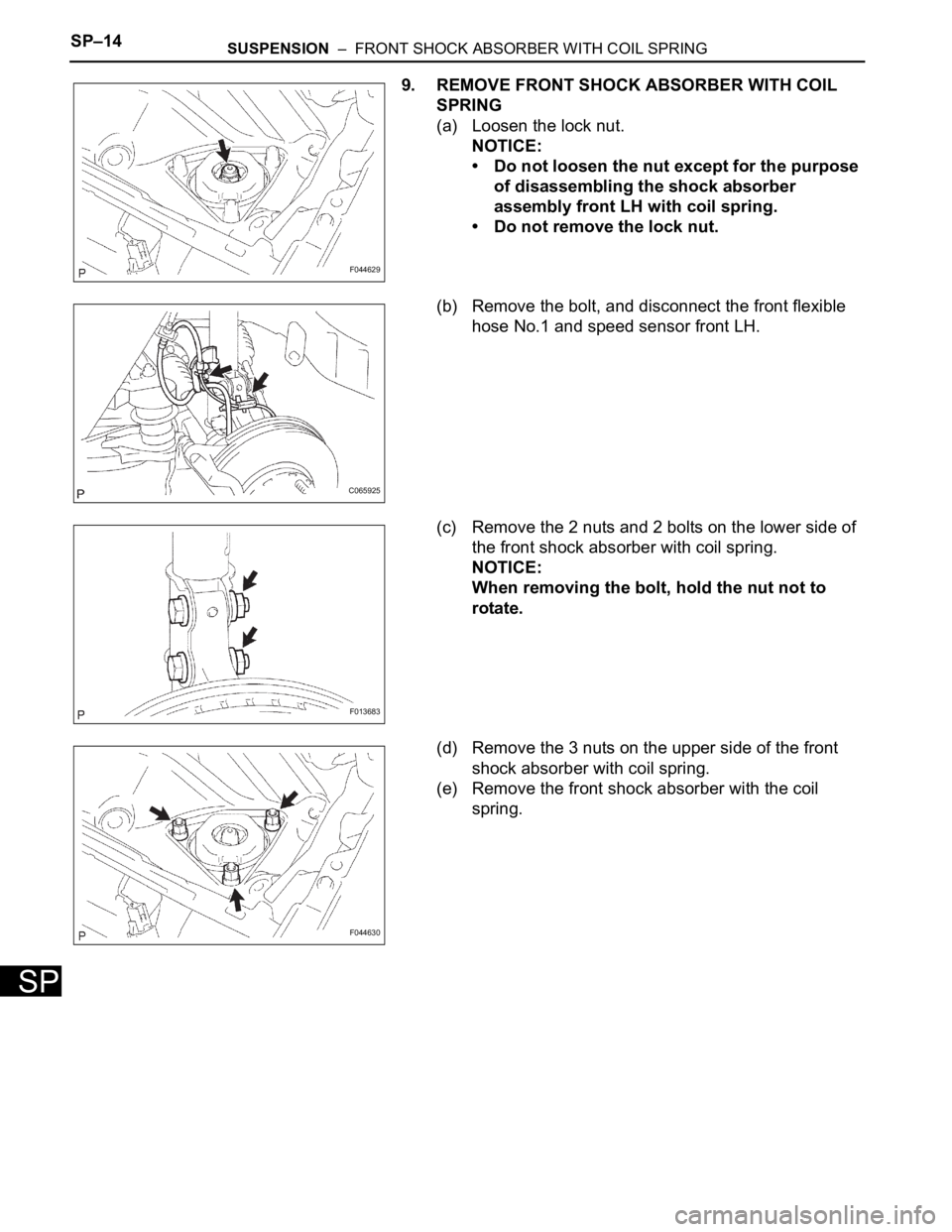
9. REMOVE FRONT SHOCK ABSORBER WITH COIL
SPRING
(a) Loosen the lock nut.
NOTICE:
• Do not loosen the nut except for the purpose
of disassembling the shock absorber
assembly front LH with coil spring.
• Do not remove the lock nut.
(b) Remove the bolt, and disconnect the front flexible
hose No.1 and speed sensor front LH.
(c) Remove the 2 nuts and 2 bolts on the lower side of
the front shock absorber with coil spring.
NOTICE:
When removing the bolt, hold the nut not to
rotate.
(d) Remove the 3 nuts on the upper side of the front
shock absorber with coil spring.
(e) Remove the front shock absorber with the coil
spring.
F044629
C065925
F013683
F044630
Page 2180 of 3000
SUSPENSION – FRONT SHOCK ABSORBER WITH COIL SPRINGSP–15
SP
DISASSEMBLY
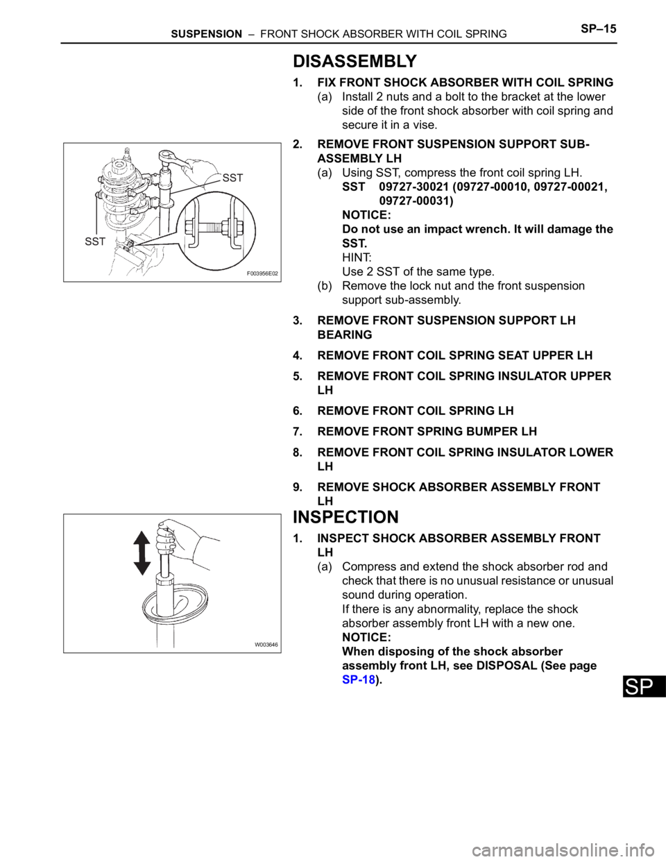
1. FIX FRONT SHOCK ABSORBER WITH COIL SPRING
(a) Install 2 nuts and a bolt to the bracket at the lower
side of the front shock absorber with coil spring and
secure it in a vise.
2. REMOVE FRONT SUSPENSION SUPPORT SUB-
ASSEMBLY LH
(a) Using SST, compress the front coil spring LH.
SST 09727-30021 (09727-00010, 09727-00021,
09727-00031)
NOTICE:
Do not use an impact wrench. It will damage the
SST.
HINT:
Use 2 SST of the same type.
(b) Remove the lock nut and the front suspension
support sub-assembly.
3. REMOVE FRONT SUSPENSION SUPPORT LH
BEARING
4. REMOVE FRONT COIL SPRING SEAT UPPER LH
5. REMOVE FRONT COIL SPRING INSULATOR UPPER
LH
6. REMOVE FRONT COIL SPRING LH
7. REMOVE FRONT SPRING BUMPER LH
8. REMOVE FRONT COIL SPRING INSULATOR LOWER
LH
9. REMOVE SHOCK ABSORBER ASSEMBLY FRONT
LH
INSPECTION
1. INSPECT SHOCK ABSORBER ASSEMBLY FRONT
LH
(a) Compress and extend the shock absorber rod and
check that there is no unusual resistance or unusual
sound during operation.
If there is any abnormality, replace the shock
absorber assembly front LH with a new one.
NOTICE:
When disposing of the shock absorber
assembly front LH, see DISPOSAL (See page
SP-18).
F003956E02
W003646