TOYOTA SIENNA 2007 Service Repair Manual
Manufacturer: TOYOTA, Model Year: 2007, Model line: SIENNA, Model: TOYOTA SIENNA 2007Pages: 3000, PDF Size: 52.26 MB
Page 2931 of 3000
AIR CONDITIONING – AIR CONDITIONING UNITAC–187
AC
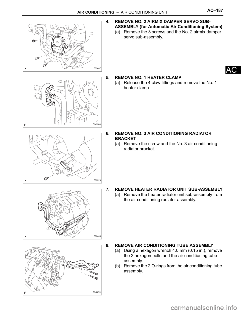
4. REMOVE NO. 2 AIRMIX DAMPER SERVO SUB-
ASSEMBLY (for Automatic Air Conditioning System)
(a) Remove the 3 screws and the No. 2 airmix damper
servo sub-assembly.
5. REMOVE NO. 1 HEATER CLAMP
(a) Release the 4 claw fittings and remove the No. 1
heater clamp.
6. REMOVE NO. 3 AIR CONDITIONING RADIATOR
BRACKET
(a) Remove the screw and the No. 3 air conditioning
radiator bracket.
7. REMOVE HEATER RADIATOR UNIT SUB-ASSEMBLY
(a) Remove the heater radiator unit sub-assembly from
the air conditioning radiator assembly.
8. REMOVE AIR CONDITIONING TUBE ASSEMBLY
(a) Using a hexagon wrench 4.0 mm (0.15 in.), remove
the 2 hexagon bolts and the air conditioning tube
assembly.
(b) Remove the 2 O-rings from the air conditioning tube
assembly.
I035467
E145280
I035523
I035469
E146674
Page 2932 of 3000
AC–188AIR CONDITIONING – AIR CONDITIONING UNIT
AC
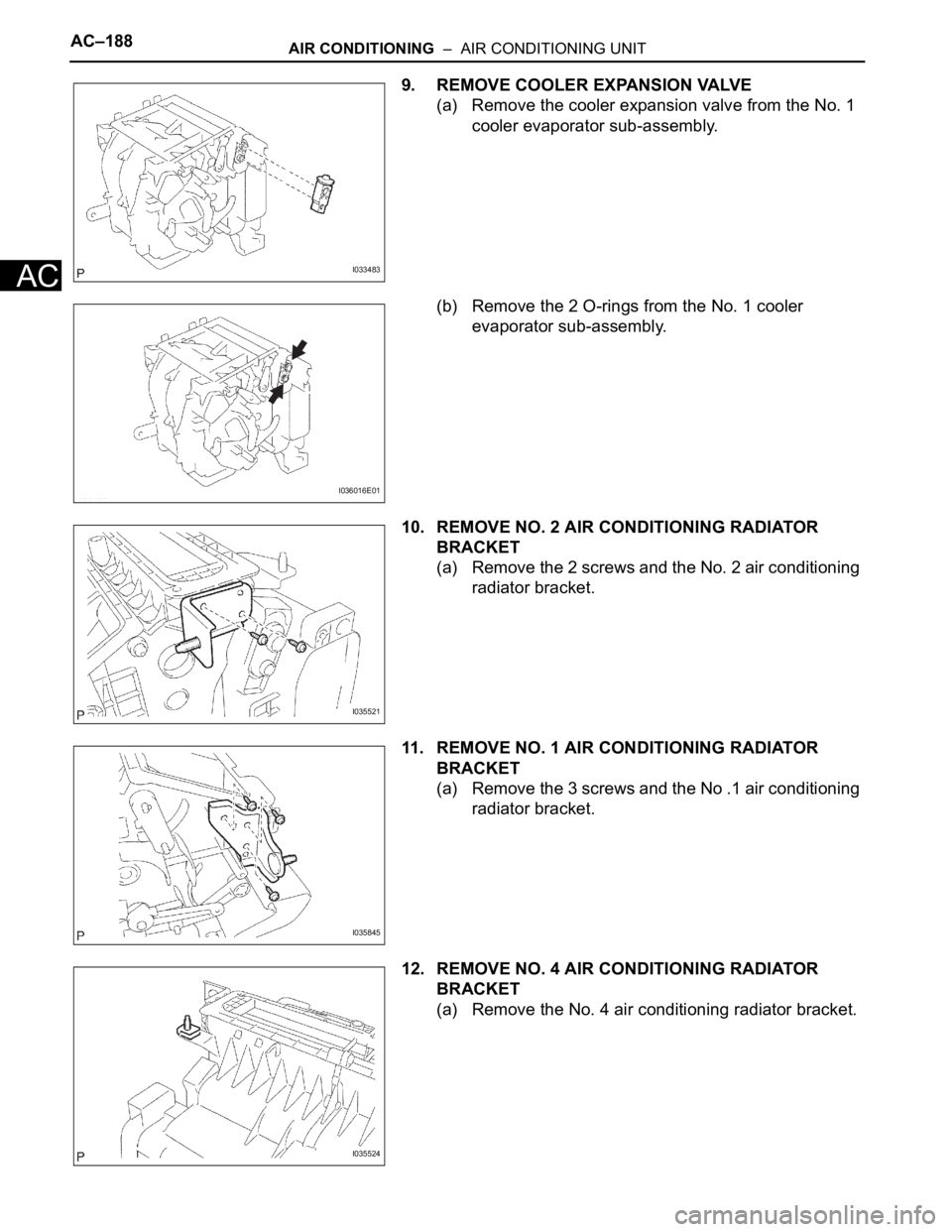
9. REMOVE COOLER EXPANSION VALVE
(a) Remove the cooler expansion valve from the No. 1
cooler evaporator sub-assembly.
(b) Remove the 2 O-rings from the No. 1 cooler
evaporator sub-assembly.
10. REMOVE NO. 2 AIR CONDITIONING RADIATOR
BRACKET
(a) Remove the 2 screws and the No. 2 air conditioning
radiator bracket.
11. REMOVE NO. 1 AIR CONDITIONING RADIATOR
BRACKET
(a) Remove the 3 screws and the No .1 air conditioning
radiator bracket.
12. REMOVE NO. 4 AIR CONDITIONING RADIATOR
BRACKET
(a) Remove the No. 4 air conditioning radiator bracket.
I033483
I036016E01
I035521
I035845
I035524
Page 2933 of 3000
AIR CONDITIONING – AIR CONDITIONING UNITAC–189
AC
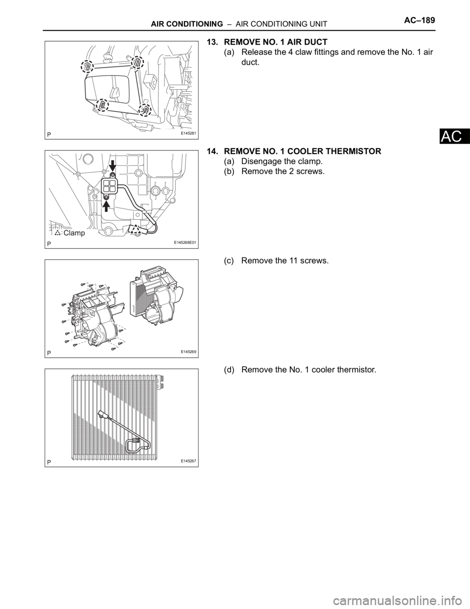
13. REMOVE NO. 1 AIR DUCT
(a) Release the 4 claw fittings and remove the No. 1 air
duct.
14. REMOVE NO. 1 COOLER THERMISTOR
(a) Disengage the clamp.
(b) Remove the 2 screws.
(c) Remove the 11 screws.
(d) Remove the No. 1 cooler thermistor.
E145281
E145268E01
E145269
E145267
Page 2934 of 3000
AC–26AIR CONDITIONING – AIR CONDITIONING SYSTEM (for Automatic Air Conditioning Sys-
tem)
AC
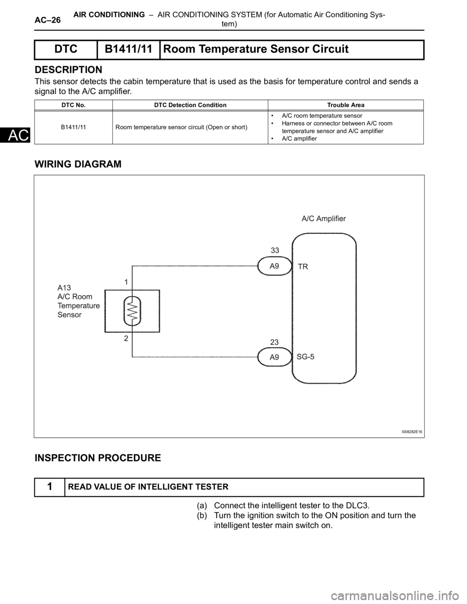
DESCRIPTION
This sensor detects the cabin temperature that is used as the basis for temperature control and sends a
signal to the A/C amplifier.
WIRING DIAGRAM
INSPECTION PROCEDURE
(a) Connect the intelligent tester to the DLC3.
(b) Turn the ignition switch to the ON position and turn the
intelligent tester main switch on.
DTC B1411/11 Room Temperature Sensor Circuit
DTC No. DTC Detection Condition Trouble Area
B1411/11 Room temperature sensor circuit (Open or short)• A/C room temperature sensor
• Harness or connector between A/C room
temperature sensor and A/C amplifier
• A/C amplifier
1READ VALUE OF INTELLIGENT TESTER
I008282E16
Page 2935 of 3000
AIR CONDITIONING – AIR CONDITIONING SYSTEM (for Automatic Air Conditioning Sys-
tem)AC–27
AC
(c) Select the item below in the DATA LIST, and read the
display on the intelligent tester.
DATA LIST / AIR CONDITIONER:
OK:
The display is as specified in the normal condition
column.
Result
B
C
A
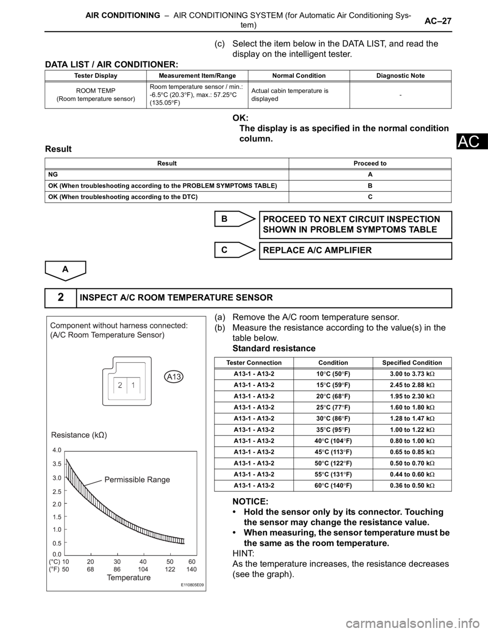
(a) Remove the A/C room temperature sensor.
(b) Measure the resistance according to the value(s) in the
table below.
Standard resistance
NOTICE:
• Hold the sensor only by its connector. Touching
the sensor may change the resistance value.
• When measuring, the sensor temperature must be
the same as the room temperature.
HINT:
As the temperature increases, the resistance decreases
(see the graph).
Tester Display Measurement Item/Range Normal Condition Diagnostic Note
ROOM TEMP
(Room temperature sensor)Room temperature sensor / min.:
-6.5
C (20.3F), max.: 57.25C
(135.05
F)Actual cabin temperature is
displayed-
Result Proceed to
NGA
OK (When troubleshooting according to the PROBLEM SYMPTOMS TABLE) B
OK (When troubleshooting according to the DTC) C
PROCEED TO NEXT CIRCUIT INSPECTION
SHOWN IN PROBLEM SYMPTOMS TABLE
REPLACE A/C AMPLIFIER
2INSPECT A/C ROOM TEMPERATURE SENSOR
E110805E09
Tester Connection Condition Specified Condition
A13-1 - A13-2 10
C (50F) 3.00 to 3.73 k
A13-1 - A13-2 15C (59F) 2.45 to 2.88 k
A13-1 - A13-2 20C (68F) 1.95 to 2.30 k
A13-1 - A13-2 25C (77F) 1.60 to 1.80 k
A13-1 - A13-2 30C (86F) 1.28 to 1.47 k
A13-1 - A13-2 35C (95F) 1.00 to 1.22 k
A13-1 - A13-2 40C (104F) 0.80 to 1.00 k
A13-1 - A13-2 45C (113F) 0.65 to 0.85 k
A13-1 - A13-2 50C (122F) 0.50 to 0.70 k
A13-1 - A13-2 55C (131F) 0.44 to 0.60 k
A13-1 - A13-2 60C (140F) 0.36 to 0.50 k
Page 2936 of 3000
AC–28AIR CONDITIONING – AIR CONDITIONING SYSTEM (for Automatic Air Conditioning Sys-
tem)
AC
NG
OK
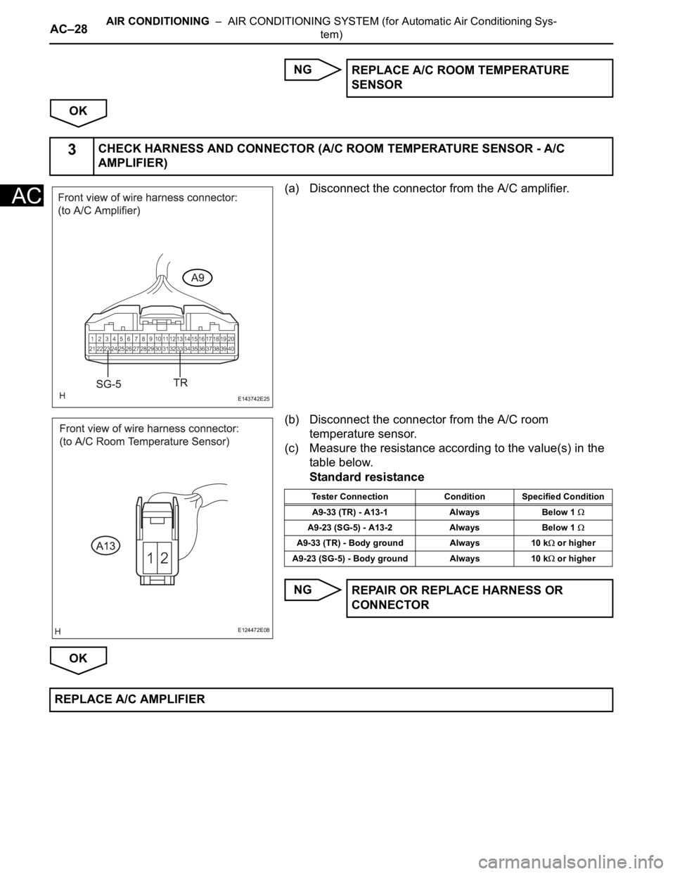
(a) Disconnect the connector from the A/C amplifier.
(b) Disconnect the connector from the A/C room
temperature sensor.
(c) Measure the resistance according to the value(s) in the
table below.
Standard resistance
NG
OKREPLACE A/C ROOM TEMPERATURE
SENSOR
3CHECK HARNESS AND CONNECTOR (A/C ROOM TEMPERATURE SENSOR - A/C
AMPLIFIER)
E143742E25
E124472E08
Tester Connection Condition Specified Condition
A9-33 (TR) - A13-1 Always Below 1
A9-23 (SG-5) - A13-2 Always Below 1
A9-33 (TR) - Body ground Always 10 k or higher
A9-23 (SG-5) - Body ground Always 10 k
or higher
REPAIR OR REPLACE HARNESS OR
CONNECTOR
REPLACE A/C AMPLIFIER
Page 2937 of 3000
AIR CONDITIONING – AIR CONDITIONING SYSTEM (for Automatic Air Conditioning Sys-
tem)AC–29
AC
DESCRIPTION
The ambient temperature sensor is installed in front of the condenser to detect the ambient temperature
which is used to control the air conditioner "AUTO" mode. This sensor is connected to the A/C amplifier
and detects fluctuations in the ambient temperature. This data is used for controlling the cabin
temperature. The sensor sends a signal to the A/C amplifier. The resistance of the ambient temperature
sensor changes in accordance with the ambient temperature. As the temperature decreases, the
resistance increases. As the temperature increases, the resistance decreases.
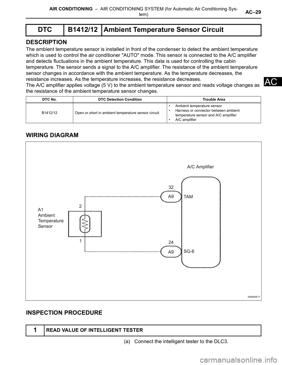
The A/C amplifier applies voltage (5 V) to the ambient temperature sensor and reads voltage changes as
the resistance of the ambient temperature sensor changes.
WIRING DIAGRAM
INSPECTION PROCEDURE
(a) Connect the intelligent tester to the DLC3.
DTC B1412/12 Ambient Temperature Sensor Circuit
DTC No. DTC Detection Condition Trouble Area
B1412/12 Open or short in ambient temperature sensor circuit• Ambient temperature sensor
• Harness or connector between ambient
temperature sensor and A/C amplifier
• A/C amplifier
1READ VALUE OF INTELLIGENT TESTER
I008282E17
Page 2938 of 3000
AC–30AIR CONDITIONING – AIR CONDITIONING SYSTEM (for Automatic Air Conditioning Sys-
tem)
AC
(b) Turn the ignition switch to the ON position and turn the
intelligent tester main switch on.
(c) Select the item below in the DATA LIST, and read the
display on the intelligent tester.
DATA LIST / AIR CONDITIONER:
OK:
The display is as specified in the normal condition
column.
Result
B
C
A
Tester Display Measurement Item/Range Normal Condition Diagnostic Note
AMBI TEMP SENS
(Ambient temperature sensor)Ambient temperature sensor /
min: -30.8
C (-23.44F), max:
50.8C (123.44F)Actual ambient temperature is
displayed-
Result Proceed to
NGA
OK (When troubleshooting according to the PROBLEM SYMPTOMS TABLE) B
OK (When troubleshooting according to the DTC) C
PROCEED TO NEXT CIRCUIT INSPECTION
SHOWN IN PROBLEM SYMPTOMS TABLE
REPLACE A/C AMPLIFIER
Page 2939 of 3000
AIR CONDITIONING – AIR CONDITIONING SYSTEM (for Automatic Air Conditioning Sys-
tem)AC–31
AC
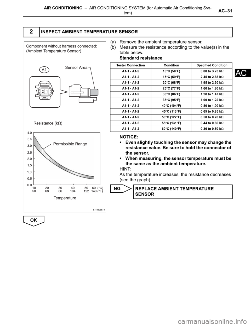
(a) Remove the ambient temperature sensor.
(b) Measure the resistance according to the value(s) in the
table below.
Standard resistance
NOTICE:
• Even slightly touching the sensor may change the
resistance value. Be sure to hold the connector of
the sensor.
• When measuring, the sensor temperature must be
the same as the ambient temperature.
HINT:
As the temperature increases, the resistance decreases
(see the graph).
NG
OK
2INSPECT AMBIENT TEMPERATURE SENSOR
E118395E14
Tester Connection Condition Specified Condition
A1-1 - A1-2 10
C (50F) 3.00 to 3.73 k
A1-1 - A1-2 15C (59F) 2.45 to 2.88 k
A1-1 - A1-2 20C (68F) 1.95 to 2.30 k
A1-1 - A1-2 25C (77F) 1.60 to 1.80 k
A1-1 - A1-2 30C (86F) 1.28 to 1.47 k
A1-1 - A1-2 35C (95F) 1.00 to 1.22 k
A1-1 - A1-2 40C (104F) 0.80 to 1.00 k
A1-1 - A1-2 45C (113F) 0.65 to 0.85 k
A1-1 - A1-2 50C (122F) 0.50 to 0.70 k
A1-1 - A1-2 55C (131F) 0.44 to 0.60 k
A1-1 - A1-2 60C (140F) 0.36 to 0.50 k
REPLACE AMBIENT TEMPERATURE
SENSOR
Page 2940 of 3000
AC–32AIR CONDITIONING – AIR CONDITIONING SYSTEM (for Automatic Air Conditioning Sys-
tem)
AC
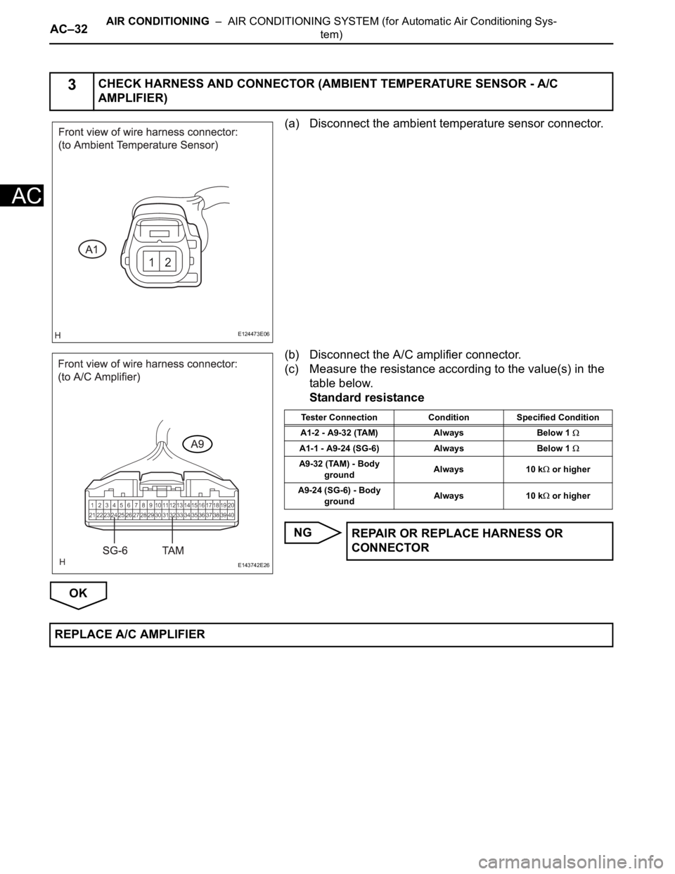
(a) Disconnect the ambient temperature sensor connector.
(b) Disconnect the A/C amplifier connector.
(c) Measure the resistance according to the value(s) in the
table below.
Standard resistance
NG
OK
3CHECK HARNESS AND CONNECTOR (AMBIENT TEMPERATURE SENSOR - A/C
AMPLIFIER)
E124473E06
E143742E26
Tester Connection Condition Specified Condition
A1-2 - A9-32 (TAM) Always Below 1
A1-1 - A9-24 (SG-6) Always Below 1
A9-32 (TAM) - Body
groundAlways 10 k or higher
A9-24 (SG-6) - Body
groundAlways 10 k
or higher
REPAIR OR REPLACE HARNESS OR
CONNECTOR
REPLACE A/C AMPLIFIER