TOYOTA SIENNA 2007 Service Repair Manual
Manufacturer: TOYOTA, Model Year: 2007, Model line: SIENNA, Model: TOYOTA SIENNA 2007Pages: 3000, PDF Size: 52.26 MB
Page 2891 of 3000
AC–148AIR CONDITIONING – AIR CONDITIONING SYSTEM (for Automatic Air Conditioning Sys-
tem)
AC
OK
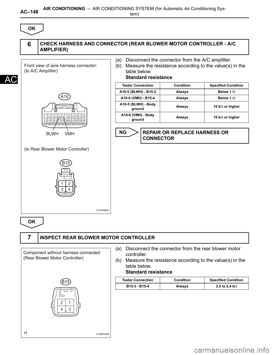
(a) Disconnect the connector from the A/C amplifier.
(b) Measure the resistance according to the value(s) in the
table below.
Standard resistance
NG
OK
(a) Disconnect the connector from the rear blower motor
controller.
(b) Measure the resistance according to the value(s) in the
table below.
Standard resistance
6CHECK HARNESS AND CONNECTOR (REAR BLOWER MOTOR CONTROLLER - A/C
AMPLIFIER)
E147506E01
Tester Connection Condition Specified Condition
A10-5 (BLWH) - B15-2 Always Below 1
A10-6 (VMH) - B15-4 Always Below 1
A10-5 (BLWH) - Body
groundAlways 10 k or higher
A10-6 (VMH) - Body
groundAlways 10 k
or higher
REPAIR OR REPLACE HARNESS OR
CONNECTOR
7INSPECT REAR BLOWER MOTOR CONTROLLER
E108912E05
Tester Connection Condition Specified Condition
B15-3 - B15-4 Always 2.0 to 2.4 k
Page 2892 of 3000
AIR CONDITIONING – AIR CONDITIONING SYSTEM (for Automatic Air Conditioning Sys-
tem)AC–149
AC
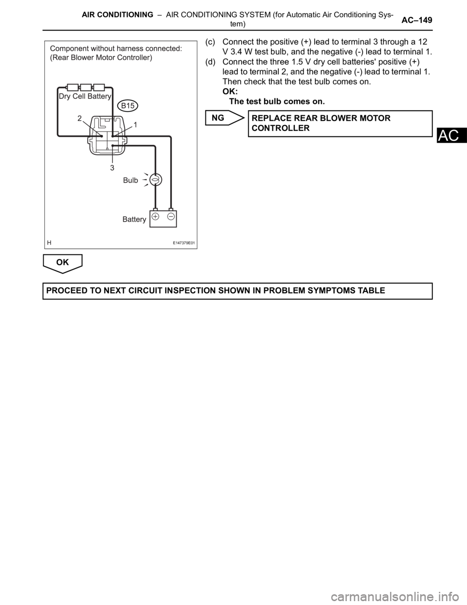
(c) Connect the positive (+) lead to terminal 3 through a 12
V 3.4 W test bulb, and the negative (-) lead to terminal 1.
(d) Connect the three 1.5 V dry cell batteries' positive (+)
lead to terminal 2, and the negative (-) lead to terminal 1.
Then check that the test bulb comes on.
OK:
The test bulb comes on.
NG
OK
E147379E01
REPLACE REAR BLOWER MOTOR
CONTROLLER
PROCEED TO NEXT CIRCUIT INSPECTION SHOWN IN PROBLEM SYMPTOMS TABLE
Page 2893 of 3000
AC–150AIR CONDITIONING – AIR CONDITIONING SYSTEM (for Automatic Air Conditioning Sys-
tem)
AC
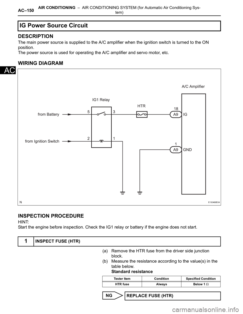
DESCRIPTION
The main power source is supplied to the A/C amplifier when the ignition switch is turned to the ON
position.
The power source is used for operating the A/C amplifier and servo motor, etc.
WIRING DIAGRAM
INSPECTION PROCEDURE
HINT:
Start the engine before inspection. Check the IG1 relay or battery if the engine does not start.
(a) Remove the HTR fuse from the driver side junction
block.
(b) Measure the resistance according to the value(s) in the
table below.
Standard resistance
NG
IG Power Source Circuit
1INSPECT FUSE (HTR)
E130466E04
Tester Item Condition Specified Condition
HTR fuse Always Below 1
REPLACE FUSE (HTR)
Page 2894 of 3000
AIR CONDITIONING – AIR CONDITIONING SYSTEM (for Automatic Air Conditioning Sys-
tem)AC–151
AC
OK
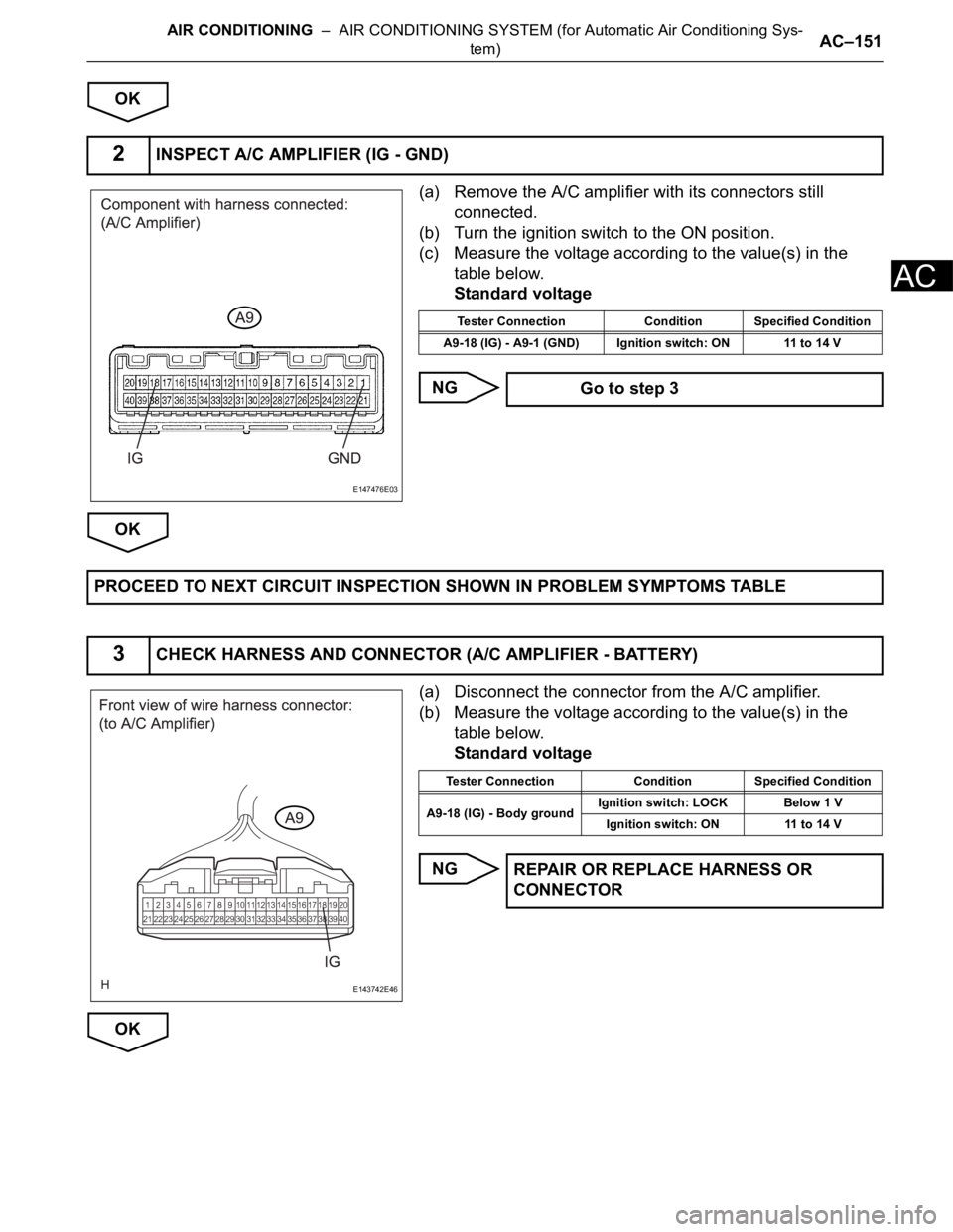
(a) Remove the A/C amplifier with its connectors still
connected.
(b) Turn the ignition switch to the ON position.
(c) Measure the voltage according to the value(s) in the
table below.
Standard voltage
NG
OK
(a) Disconnect the connector from the A/C amplifier.
(b) Measure the voltage according to the value(s) in the
table below.
Standard voltage
NG
OK
2INSPECT A/C AMPLIFIER (IG - GND)
E147476E03
Tester Connection Condition Specified Condition
A9-18 (IG) - A9-1 (GND) Ignition switch: ON 11 to 14 V
Go to step 3
PROCEED TO NEXT CIRCUIT INSPECTION SHOWN IN PROBLEM SYMPTOMS TABLE
3CHECK HARNESS AND CONNECTOR (A/C AMPLIFIER - BATTERY)
E143742E46
Tester Connection Condition Specified Condition
A9-18 (IG) - Body groundIgnition switch: LOCK Below 1 V
Ignition switch: ON 11 to 14 V
REPAIR OR REPLACE HARNESS OR
CONNECTOR
Page 2895 of 3000
AC–152AIR CONDITIONING – AIR CONDITIONING SYSTEM (for Automatic Air Conditioning Sys-
tem)
AC
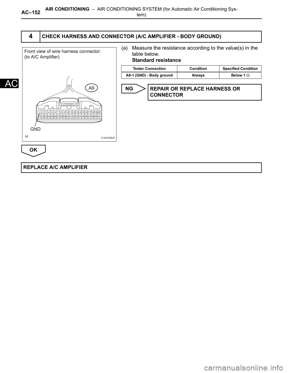
(a) Measure the resistance according to the value(s) in the
table below.
Standard resistance
NG
OK
4CHECK HARNESS AND CONNECTOR (A/C AMPLIFIER - BODY GROUND)
E143742E47
Tester Connection Condition Specified Condition
A9-1 (GND) - Body ground Always Below 1
REPAIR OR REPLACE HARNESS OR
CONNECTOR
REPLACE A/C AMPLIFIER
Page 2896 of 3000
AIR CONDITIONING – AIR CONDITIONING SYSTEM (for Automatic Air Conditioning Sys-
tem)AC–153
AC
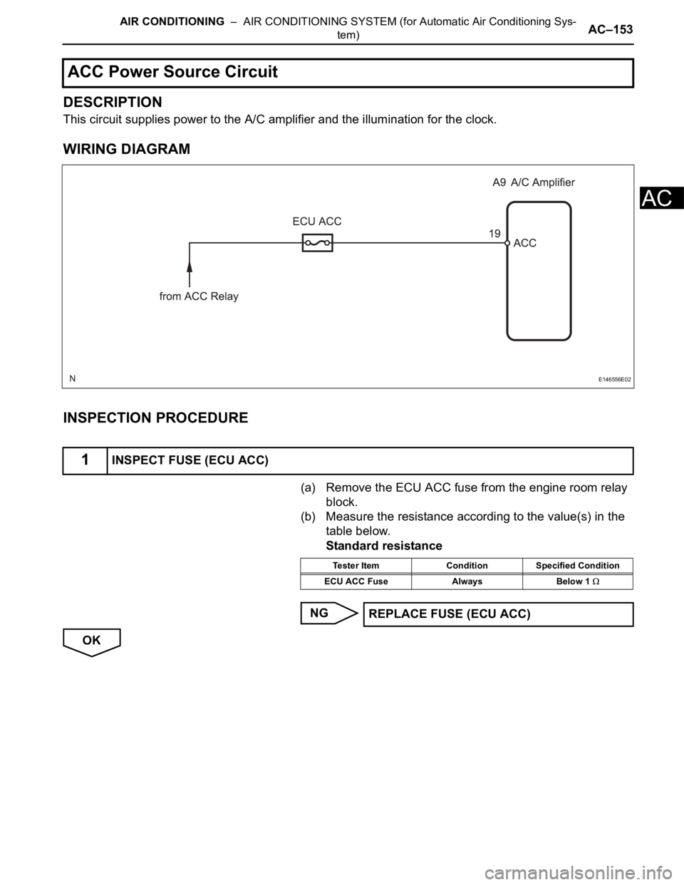
DESCRIPTION
This circuit supplies power to the A/C amplifier and the illumination for the clock.
WIRING DIAGRAM
INSPECTION PROCEDURE
(a) Remove the ECU ACC fuse from the engine room relay
block.
(b) Measure the resistance according to the value(s) in the
table below.
Standard resistance
NG
OK
ACC Power Source Circuit
1INSPECT FUSE (ECU ACC)
E146556E02
Tester Item Condition Specified Condition
ECU ACC Fuse Always Below 1
REPLACE FUSE (ECU ACC)
Page 2897 of 3000
AC–154AIR CONDITIONING – AIR CONDITIONING SYSTEM (for Automatic Air Conditioning Sys-
tem)
AC
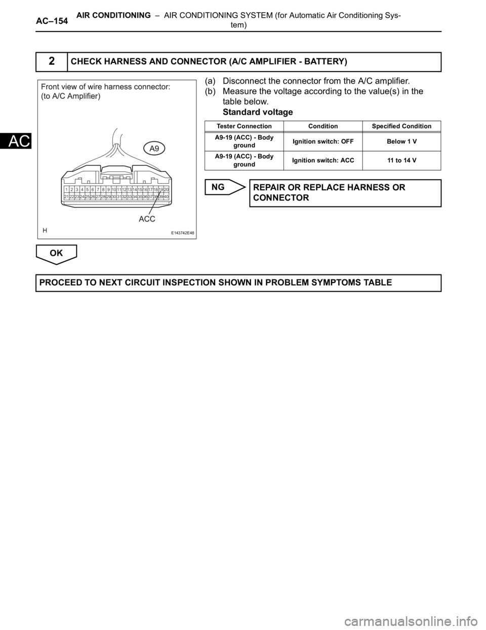
(a) Disconnect the connector from the A/C amplifier.
(b) Measure the voltage according to the value(s) in the
table below.
Standard voltage
NG
OK
2CHECK HARNESS AND CONNECTOR (A/C AMPLIFIER - BATTERY)
E143742E48
Tester Connection Condition Specified Condition
A9-19 (ACC) - Body
groundIgnition switch: OFF Below 1 V
A9-19 (ACC) - Body
groundIgnition switch: ACC 11 to 14 V
REPAIR OR REPLACE HARNESS OR
CONNECTOR
PROCEED TO NEXT CIRCUIT INSPECTION SHOWN IN PROBLEM SYMPTOMS TABLE
Page 2898 of 3000
AIR CONDITIONING – AIR CONDITIONING SYSTEM (for Automatic Air Conditioning Sys-
tem)AC–155
AC
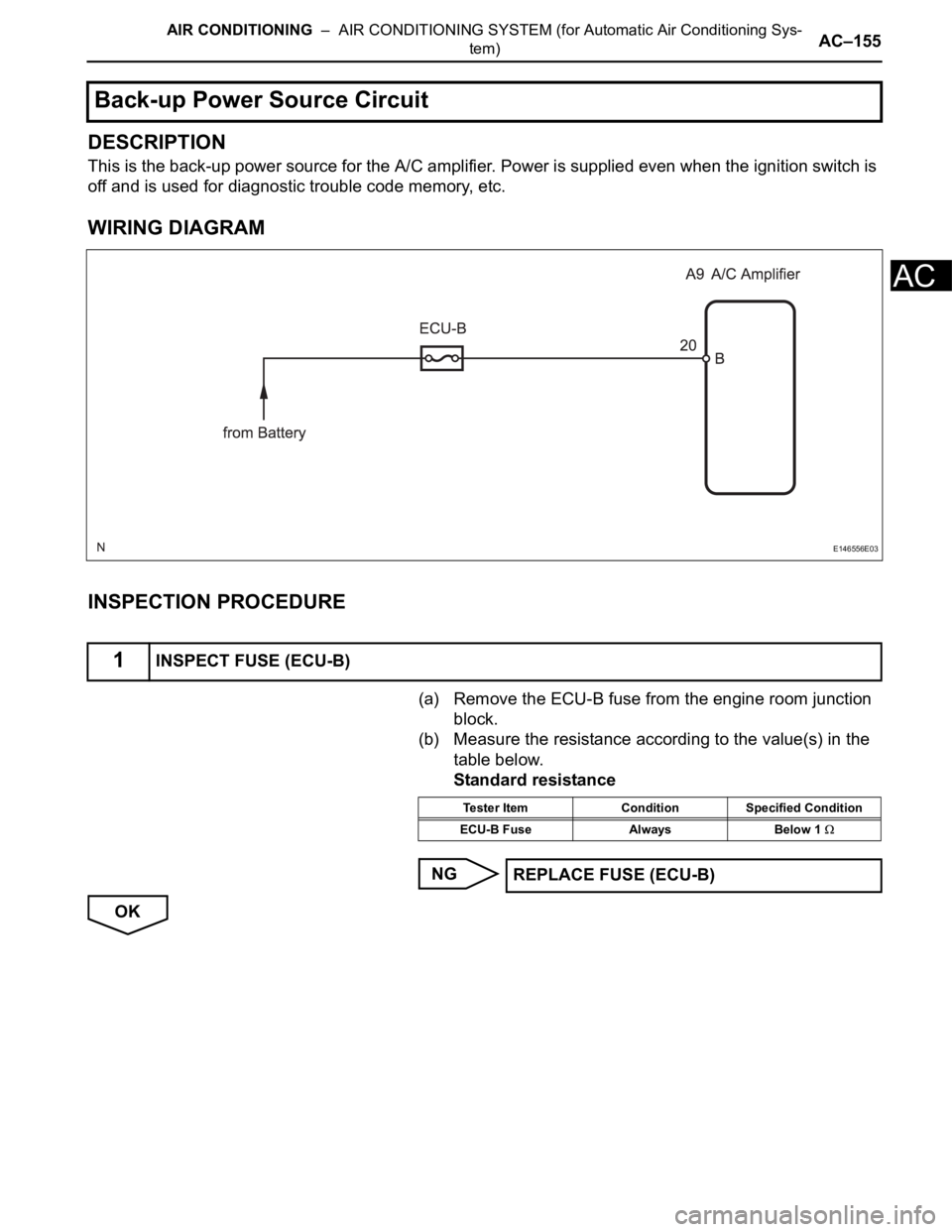
DESCRIPTION
This is the back-up power source for the A/C amplifier. Power is supplied even when the ignition switch is
off and is used for diagnostic trouble code memory, etc.
WIRING DIAGRAM
INSPECTION PROCEDURE
(a) Remove the ECU-B fuse from the engine room junction
block.
(b) Measure the resistance according to the value(s) in the
table below.
Standard resistance
NG
OK
Back-up Power Source Circuit
1INSPECT FUSE (ECU-B)
E146556E03
Tester Item Condition Specified Condition
ECU-B Fuse Always Below 1
REPLACE FUSE (ECU-B)
Page 2899 of 3000
AC–156AIR CONDITIONING – AIR CONDITIONING SYSTEM (for Automatic Air Conditioning Sys-
tem)
AC
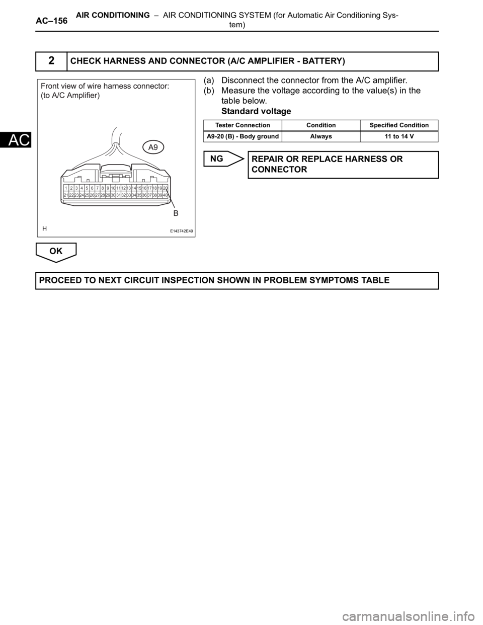
(a) Disconnect the connector from the A/C amplifier.
(b) Measure the voltage according to the value(s) in the
table below.
Standard voltage
NG
OK
2CHECK HARNESS AND CONNECTOR (A/C AMPLIFIER - BATTERY)
E143742E49
Tester Connection Condition Specified Condition
A9-20 (B) - Body ground Always 11 to 14 V
REPAIR OR REPLACE HARNESS OR
CONNECTOR
PROCEED TO NEXT CIRCUIT INSPECTION SHOWN IN PROBLEM SYMPTOMS TABLE
Page 2900 of 3000
AIR CONDITIONING – AIR CONDITIONING SYSTEM (for Automatic Air Conditioning Sys-
tem)AC–11
AC
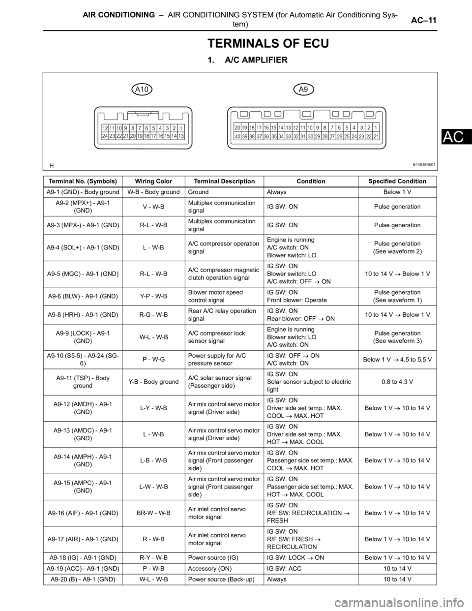
TERMINALS OF ECU
1. A/C AMPLIFIER
Terminal No. (Symbols) Wiring Color Terminal Description ConditionSpecified Condition
A9-1 (GND) - Body ground W-B - Body ground Ground Always Below 1 V
A9-2 (MPX+) - A9-1
(GND)V - W-BMultiplex communication
signalIG SW: ON Pulse generation
A9-3 (MPX-) - A9-1 (GND) R-L - W-BMultiplex communication
signalIG SW: ON Pulse generation
A9-4 (SOL+) - A9-1 (GND) L - W-BA/C compressor operation
signalEngine is running
A/C switch: ON
Blower switch: LOPulse generation
(See waveform 2)
A9-5 (MGC) - A9-1 (GND) R-L - W-BA/C compressor magnetic
clutch operation signalIG SW: ON
Blower switch: LO
A/C switch: OFF
ON10 to 14 V Below 1 V
A9-6 (BLW) - A9-1 (GND) Y-P - W-BBlower motor speed
control signalIG SW: ON
Front blower: OperatePulse generation
(See waveform 1)
A9-8 (HRH) - A9-1 (GND) R-G - W-BRear A/C relay operation
signalIG SW: ON
Rear blower: OFF
ON10 to 14 V Below 1 V
A9-9 (LOCK) - A9-1
(GND)W-L - W-BA/C compressor lock
sensor signalEngine is running
Blower switch: LO
A/C switch: ONPulse generation
(See waveform 3)
A9-10 (S5-5) - A9-24 (SG-
6)P - W-GPower supply for A/C
pressure sensorIG SW: OFF
ON
A/C switch: ONBelow 1 V 4.5 to 5.5 V
A9-11 (TSP) - Body
groundY-B - Body groundA/C solar sensor signal
(Passenger side)IG SW: ON
Solar sensor subject to electric
light0.8 to 4.3 V
A9-12 (AMDH) - A9-1
(GND)L-Y - W-BAir mix control servo motor
signal (Driver side)IG SW: ON
Driver side set temp.: MAX.
COOL
MAX. HOTBelow 1 V
10 to 14 V
A9-13 (AMDC) - A9-1
(GND)L - W-BAir mix control servo motor
signal (Driver side)IG SW: ON
Driver side set temp.: MAX.
HOT
MAX. COOLBelow 1 V 10 to 14 V
A9-14 (AMPH) - A9-1
(GND)L-B - W-BAir mix control servo motor
signal (Front passenger
side)IG SW: ON
Passenger side set temp.: MAX.
COOL
MAX. HOTBelow 1 V
10 to 14 V
A9-15 (AMPC) - A9-1
(GND)L-W - W-BAir mix control servo motor
signal (Front passenger
side)IG SW: ON
Passenger side set temp.: MAX.
HOT
MAX. COOLBelow 1 V
10 to 14 V
A9-16 (AIF) - A9-1 (GND) BR-W - W-BAir inlet control servo
motor signalIG SW: ON
R/F SW: RECIRCULATION
FRESHBelow 1 V 10 to 14 V
A9-17 (AIR) - A9-1 (GND) R - W-BAir inlet control servo
motor signalIG SW: ON
R/F SW: FRESH
RECIRCULATIONBelow 1 V 10 to 14 V
A9-18 (IG) - A9-1 (GND) R-Y - W-B Power source (IG) IG SW: LOCK
ON Below 1 V 10 to 14 V
A9-19 (ACC) - A9-1 (GND) P - W-B Accessory (ON) IG SW: ACC 10 to 14 V
A9-20 (B) - A9-1 (GND) W-L - W-B Power source (Back-up) Always 10 to 14 V
E145189E01