TOYOTA SIENNA 2007 Service Service Manual
Manufacturer: TOYOTA, Model Year: 2007, Model line: SIENNA, Model: TOYOTA SIENNA 2007Pages: 3000, PDF Size: 52.26 MB
Page 41 of 3000
EM–422GR-FE ENGINE MECHANICAL – ENGINE ASSEMBLY
EM
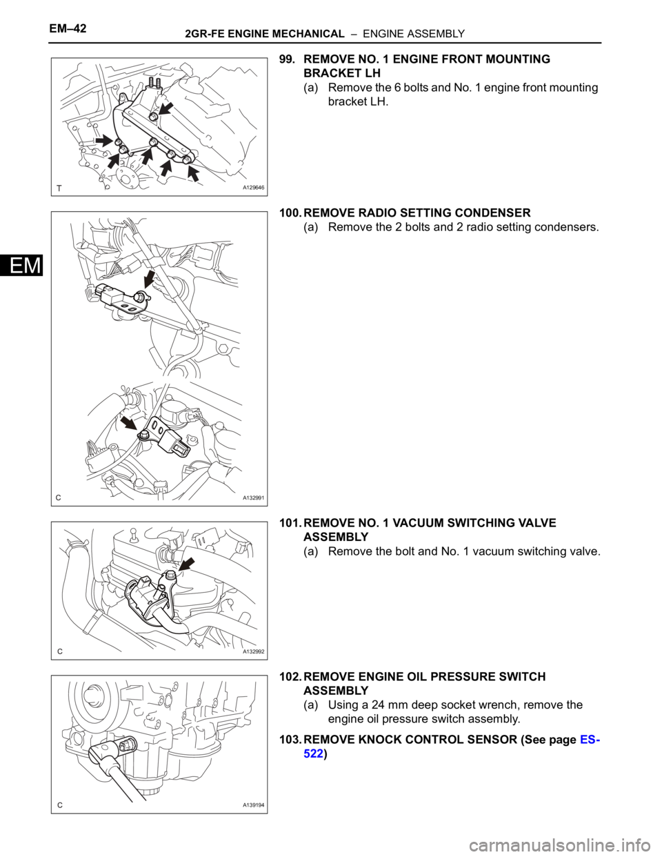
99. REMOVE NO. 1 ENGINE FRONT MOUNTING
BRACKET LH
(a) Remove the 6 bolts and No. 1 engine front mounting
bracket LH.
100. REMOVE RADIO SETTING CONDENSER
(a) Remove the 2 bolts and 2 radio setting condensers.
101. REMOVE NO. 1 VACUUM SWITCHING VALVE
ASSEMBLY
(a) Remove the bolt and No. 1 vacuum switching valve.
102. REMOVE ENGINE OIL PRESSURE SWITCH
ASSEMBLY
(a) Using a 24 mm deep socket wrench, remove the
engine oil pressure switch assembly.
103. REMOVE KNOCK CONTROL SENSOR (See page ES-
522)
A129646
A132991
A132992
A139194
Page 42 of 3000
2GR-FE FUEL – FUEL SYSTEMFU–5
FU
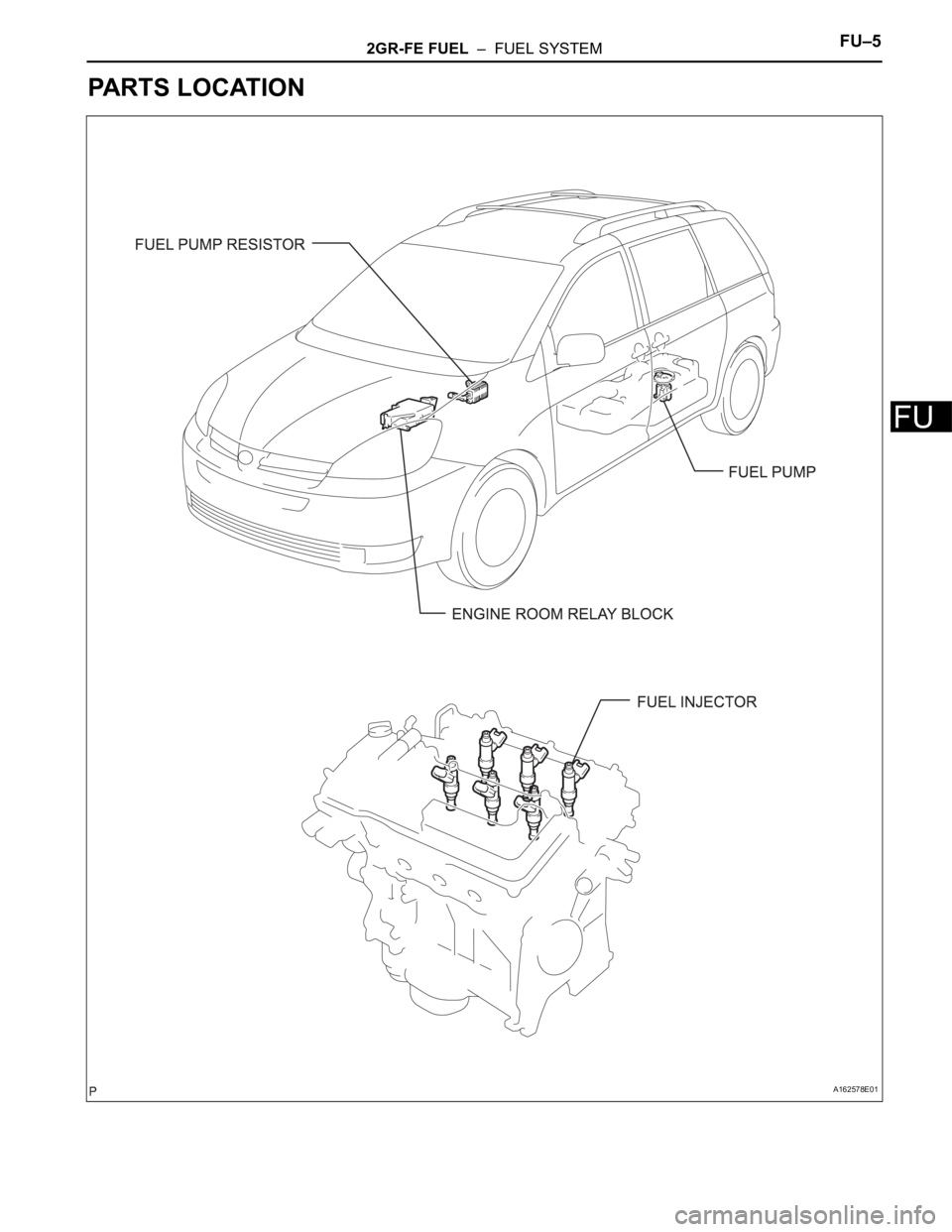
PARTS LOCATION
A162578E01
Page 43 of 3000
FU–62GR-FE FUEL – FUEL SYSTEM
FU
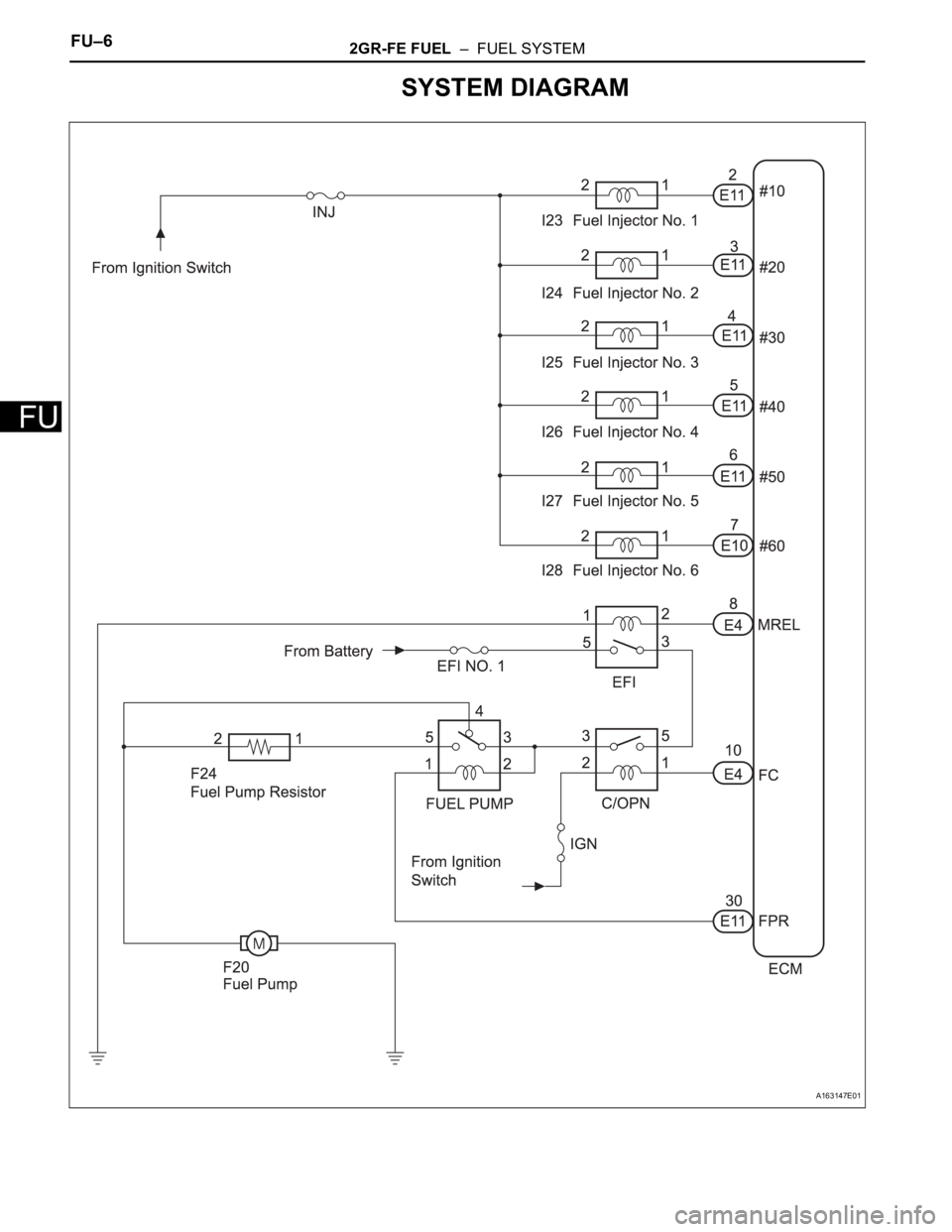
SYSTEM DIAGRAM
A163147E01
Page 44 of 3000
2GR-FE EMISSION CONTROL – EMISSION CONTROL SYSTEMEC–5
EC
ON-VEHICLE INSPECTION
1. INSPECT FUEL CUT RPM
(a) Increase the engine speed to at least 3500 rpm.
(b) Use a sound scope to check for injector operating
sounds.
(c) Check that when the throttle lever is released,
injector operating sounds stop momentarily (at 2500
rpm) and then resume (at 1400 rpm).
Standard
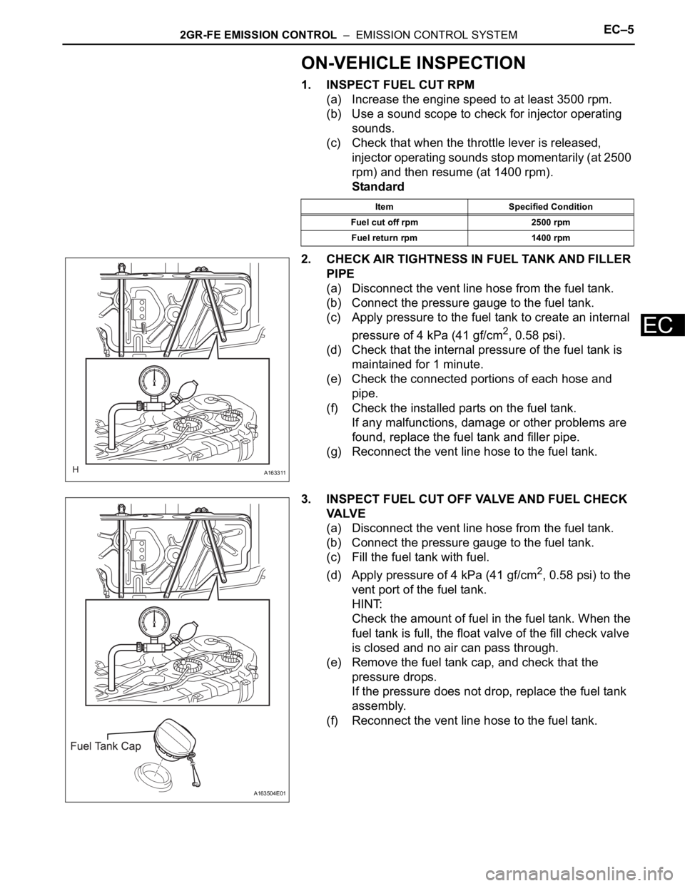
2. CHECK AIR TIGHTNESS IN FUEL TANK AND FILLER
PIPE
(a) Disconnect the vent line hose from the fuel tank.
(b) Connect the pressure gauge to the fuel tank.
(c) Apply pressure to the fuel tank to create an internal
pressure of 4 kPa (41 gf/cm
2, 0.58 psi).
(d) Check that the internal pressure of the fuel tank is
maintained for 1 minute.
(e) Check the connected portions of each hose and
pipe.
(f) Check the installed parts on the fuel tank.
If any malfunctions, damage or other problems are
found, replace the fuel tank and filler pipe.
(g) Reconnect the vent line hose to the fuel tank.
3. INSPECT FUEL CUT OFF VALVE AND FUEL CHECK
VA LV E
(a) Disconnect the vent line hose from the fuel tank.
(b) Connect the pressure gauge to the fuel tank.
(c) Fill the fuel tank with fuel.
(d) Apply pressure of 4 kPa (41 gf/cm
2, 0.58 psi) to the
vent port of the fuel tank.
HINT:
Check the amount of fuel in the fuel tank. When the
fuel tank is full, the float valve of the fill check valve
is closed and no air can pass through.
(e) Remove the fuel tank cap, and check that the
pressure drops.
If the pressure does not drop, replace the fuel tank
assembly.
(f) Reconnect the vent line hose to the fuel tank.
Item Specified Condition
Fuel cut off rpm 2500 rpm
Fuel return rpm 1400 rpm
A163311
A163504E01
Page 45 of 3000
EC–62GR-FE EMISSION CONTROL – EMISSION CONTROL SYSTEM
EC
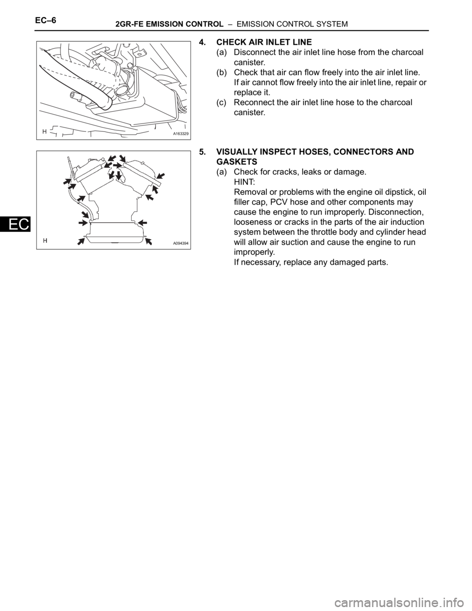
4. CHECK AIR INLET LINE
(a) Disconnect the air inlet line hose from the charcoal
canister.
(b) Check that air can flow freely into the air inlet line.
If air cannot flow freely into the air inlet line, repair or
replace it.
(c) Reconnect the air inlet line hose to the charcoal
canister.
5. VISUALLY INSPECT HOSES, CONNECTORS AND
GASKETS
(a) Check for cracks, leaks or damage.
HINT:
Removal or problems with the engine oil dipstick, oil
filler cap, PCV hose and other components may
cause the engine to run improperly. Disconnection,
looseness or cracks in the parts of the air induction
system between the throttle body and cylinder head
will allow air suction and cause the engine to run
improperly.
If necessary, replace any damaged parts.
A163329
A094394
Page 46 of 3000
2GR-FE INTAKE – INTAKE AIR CONTROL VALVEIT–5
IT
REMOVAL
1. REMOVE NO. 2 AIR CLEANER INLET (See page EM-
28)
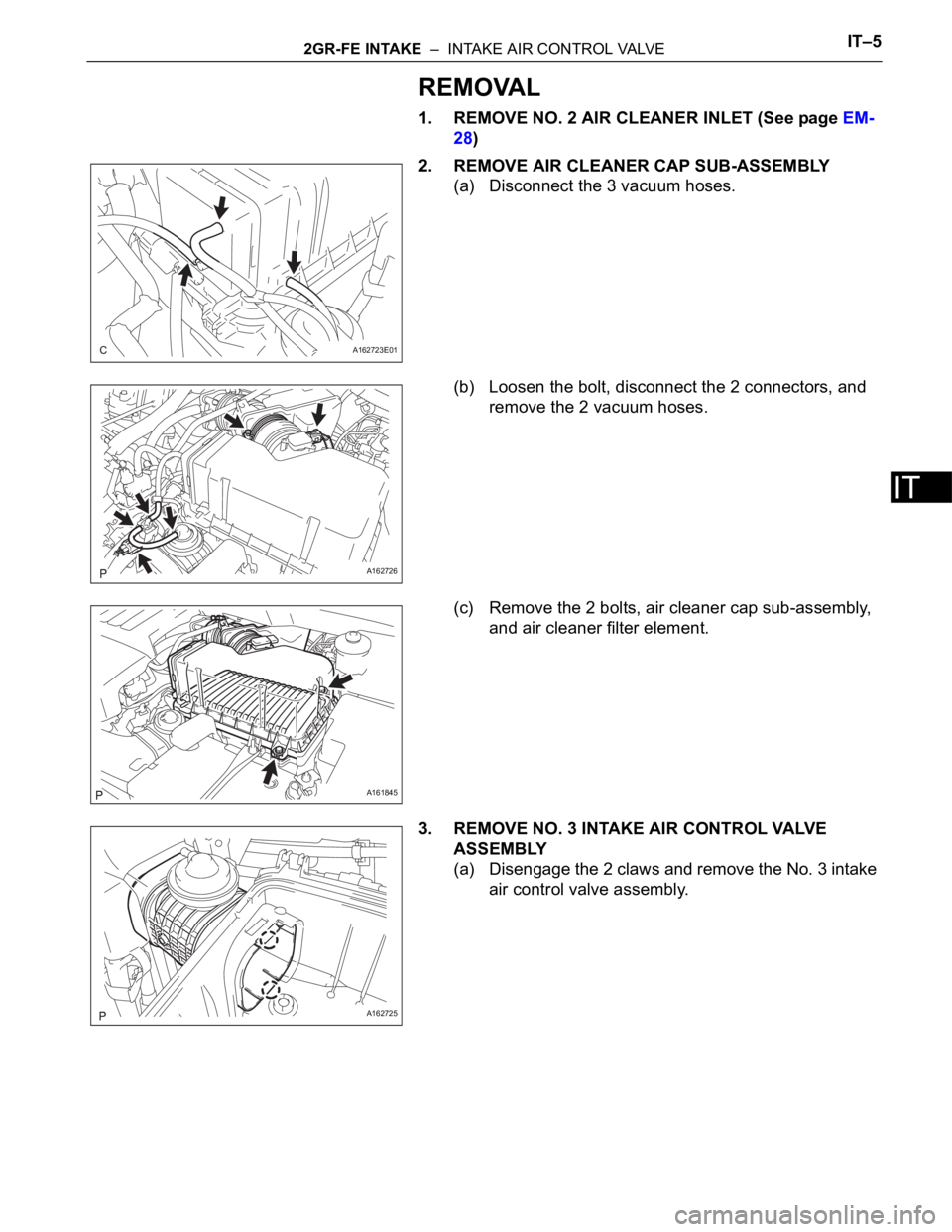
2. REMOVE AIR CLEANER CAP SUB-ASSEMBLY
(a) Disconnect the 3 vacuum hoses.
(b) Loosen the bolt, disconnect the 2 connectors, and
remove the 2 vacuum hoses.
(c) Remove the 2 bolts, air cleaner cap sub-assembly,
and air cleaner filter element.
3. REMOVE NO. 3 INTAKE AIR CONTROL VALVE
ASSEMBLY
(a) Disengage the 2 claws and remove the No. 3 intake
air control valve assembly.
A162723E01
A162726
A161845
A162725
Page 47 of 3000
IT–62GR-FE INTAKE – INTAKE AIR CONTROL VALVE
IT
INSPECTION
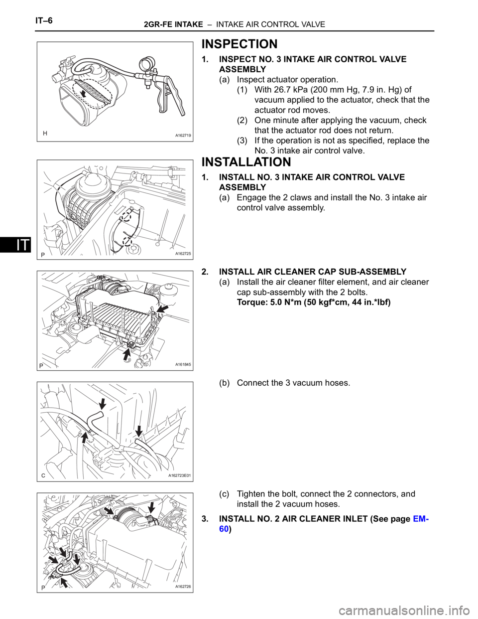
1. INSPECT NO. 3 INTAKE AIR CONTROL VALVE
ASSEMBLY
(a) Inspect actuator operation.
(1) With 26.7 kPa (200 mm Hg, 7.9 in. Hg) of
vacuum applied to the actuator, check that the
actuator rod moves.
(2) One minute after applying the vacuum, check
that the actuator rod does not return.
(3) If the operation is not as specified, replace the
No. 3 intake air control valve.
INSTALLATION
1. INSTALL NO. 3 INTAKE AIR CONTROL VALVE
ASSEMBLY
(a) Engage the 2 claws and install the No. 3 intake air
control valve assembly.
2. INSTALL AIR CLEANER CAP SUB-ASSEMBLY
(a) Install the air cleaner filter element, and air cleaner
cap sub-assembly with the 2 bolts.
Torque: 5.0 N*m (50 kgf*cm, 44 in.*lbf)
(b) Connect the 3 vacuum hoses.
(c) Tighten the bolt, connect the 2 connectors, and
install the 2 vacuum hoses.
3. INSTALL NO. 2 AIR CLEANER INLET (See page EM-
60)
A162719
A162725
A161845
A162723E01
A162726
Page 48 of 3000
IN–36INTRODUCTION – HOW TO TROUBLESHOOT ECU CONTROLLED SYSTEMS
IN
HOW TO PROCEED WITH
TROUBLESHOOTING
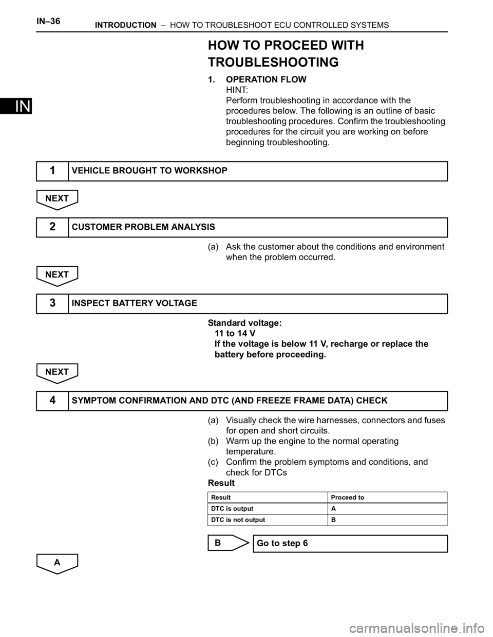
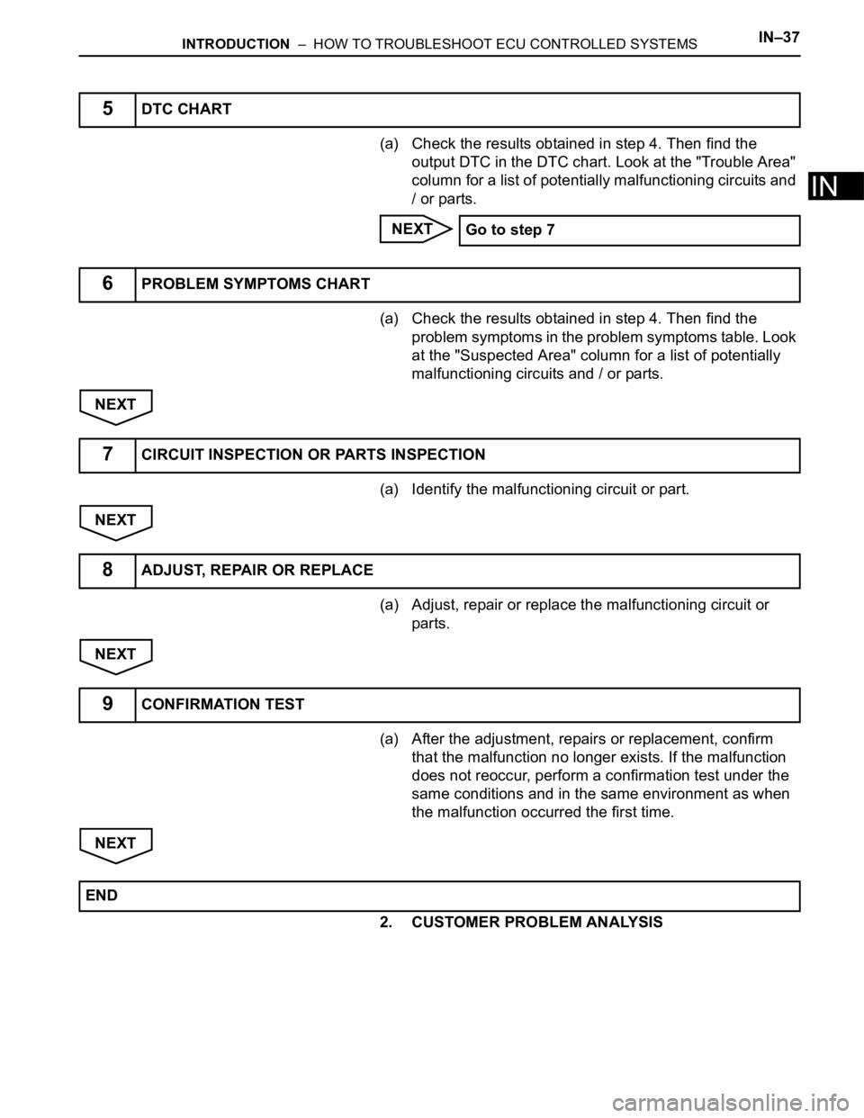
1. OPERATION FLOW
HINT:
Perform troubleshooting in accordance with the
procedures below. The following is an outline of basic
troubleshooting procedures. Confirm the troubleshooting
procedures for the circuit you are working on before
beginning troubleshooting.
NEXT
(a) Ask the customer about the conditions and environment
when the problem occurred.
NEXT
Standard voltage:
11 to 14 V
If the voltage is below 11 V, recharge or replace the
battery before proceeding.
NEXT
(a) Visually check the wire harnesses, connectors and fuses
for open and short circuits.
(b) Warm up the engine to the normal operating
temperature.
(c) Confirm the problem symptoms and conditions, and
check for DTCs
Result
B
A
1VEHICLE BROUGHT TO WORKSHOP
2CUSTOMER PROBLEM ANALYSIS
3INSPECT BATTERY VOLTAGE
4SYMPTOM CONFIRMATION AND DTC (AND FREEZE FRAME DATA) CHECK
Result Proceed to
DTC is output A
DTC is not output B
Go to step 6
Page 49 of 3000
INTRODUCTION – HOW TO TROUBLESHOOT ECU CONTROLLED SYSTEMSIN–37
IN
(a) Check the results obtained in step 4. Then find the
output DTC in the DTC chart. Look at the "Trouble Area"
column for a list of potentially malfunctioning circuits and
/ or parts.
NEXT
(a) Check the results obtained in step 4. Then find the
problem symptoms in the problem symptoms table. Look
at the "Suspected Area" column for a list of potentially
malfunctioning circuits and / or parts.
NEXT
(a) Identify the malfunctioning circuit or part.
NEXT
(a) Adjust, repair or replace the malfunctioning circuit or
parts.
NEXT
(a) After the adjustment, repairs or replacement, confirm
that the malfunction no longer exists. If the malfunction
does not reoccur, perform a confirmation test under the
same conditions and in the same environment as when
the malfunction occurred the first time.
NEXT
2. CUSTOMER PROBLEM ANALYSIS
5DTC CHART
Go to step 7
6PROBLEM SYMPTOMS CHART
7CIRCUIT INSPECTION OR PARTS INSPECTION
8ADJUST, REPAIR OR REPLACE
9CONFIRMATION TEST
END
Page 50 of 3000

IN–38INTRODUCTION – HOW TO TROUBLESHOOT ECU CONTROLLED SYSTEMS
IN
HINT:
• In troubleshooting, confirm that the problem symptoms
have been accurately identified. Preconceptions should be
discarded in order to make an accurate judgment. To
clearly understand what the problem symptoms are, it is
extremely important to ask the customer about the
problem and the conditions at the time the malfunction
occurred.
• Gather as much information as possible for reference.
Past problems that seem unrelated may also help in some
cases.
• The following 5 items are important points in the problem
analysis:
3. SYMPTOM CONFIRMATION AND DIAGNOSTIC
TROUBLE CODE
HINT:
The diagnostic system in the SIENNA has various
functions.
• The first function is the Diagnostic Trouble Code
(DTC) check. A DTC is a code stored in the ECU
memory whenever a malfunction in the signal circuits
to the ECU occurs. In a DTC check, a previous
malfunction's DTC can be checked by a technician
during troubleshooting.
• Another function is the Input Signal Check, which
checks if the signals from various switches are sent to
the ECU correctly.
By using these functions, the problem areas can be
narrowed down and troubleshooting is more effective.
Diagnostic functions are incorporated in the following
system in the SIENNA.
What Vehicle model, system name
When Date, time, occurrence frequency
Where Road conditions
Under what conditions? Running conditions, driving conditions, weather conditions
How did it happen? Problem symptoms
SystemSYMPTOM CONFIRMATION AND DIAGNOSTIC TROUBLE CODE
DTC Check
(Normal Mode)DTC Check
(Check Mode)Sensor Check/
Test Mode
(Input Signal
Check)Data List Active Test
2GR-FE SFI System
X
U151E Automatic Transaxle SystemX
U151F Automatic Transaxle SystemX
Tire pressure warning systemXX
Anti-lock Brake System
X
Vehicle Stability Control SystemX
Air Conditioning System (for Manual Air
Conditioning System)XXXXX
Air Conditioning System (for Automatic Air
Conditioning System)
XX
Airbag SystemXX
Occupant Classification System
XXX