transmission TOYOTA SIENNA 2007 Service Service Manual
[x] Cancel search | Manufacturer: TOYOTA, Model Year: 2007, Model line: SIENNA, Model: TOYOTA SIENNA 2007Pages: 3000, PDF Size: 52.26 MB
Page 991 of 3000

EM–322GR-FE ENGINE MECHANICAL – ENGINE ASSEMBLY
EM
(c) Remove the clip and disconnect the transmission
control cable assembly from the control cable
bracket.
(d) Disconnect the control cable from the control cable
clamp.
38. DISCONNECT RETURN TUBE SUB-ASSEMBLY
(a) Using pliers, grip the claws of the 2 clips and slide
the 2 clips to disconnect the 2 return tube sub-
assemblies.
(b) Drain the power steering fluid.
NOTICE:
Take care not to damage the hose protector.
39. DISCONNECT NO. 1 OIL RESERVOIR TO PUMP
HOSE
(a) Using pliers, grip the claws of the clip and slide the
clip to disconnect the No. 1 oil reservoir to pump
hose from the oil reservoir tank.
40. DISCONNECT ENGINE WIRE
(a) Disconnect the engine wire from the engine room
junction block.
(1) Remove the nut and separate the wire harness.
(2) Using a screwdriver, unlock the engine room
junction block. Pull the engine room junction
block upward.
C089134E01
C090579
A163268
A155029
A155037
Page 1014 of 3000
2GR-FE ENGINE MECHANICAL – ENGINE ASSEMBLYEM–55
EM
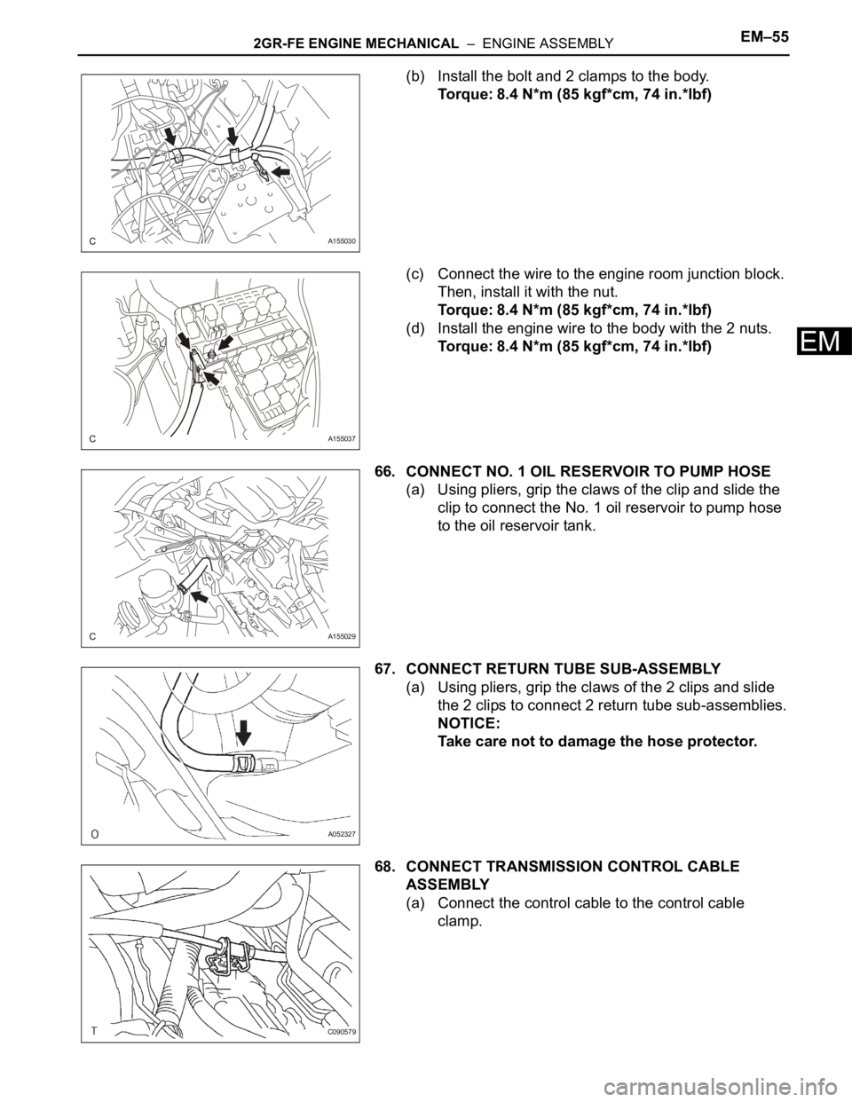
(b) Install the bolt and 2 clamps to the body.
Torque: 8.4 N*m (85 kgf*cm, 74 in.*lbf)
(c) Connect the wire to the engine room junction block.
Then, install it with the nut.
Torque: 8.4 N*m (85 kgf*cm, 74 in.*lbf)
(d) Install the engine wire to the body with the 2 nuts.
Torque: 8.4 N*m (85 kgf*cm, 74 in.*lbf)
66. CONNECT NO. 1 OIL RESERVOIR TO PUMP HOSE
(a) Using pliers, grip the claws of the clip and slide the
clip to connect the No. 1 oil reservoir to pump hose
to the oil reservoir tank.
67. CONNECT RETURN TUBE SUB-ASSEMBLY
(a) Using pliers, grip the claws of the 2 clips and slide
the 2 clips to connect 2 return tube sub-assemblies.
NOTICE:
Take care not to damage the hose protector.
68. CONNECT TRANSMISSION CONTROL CABLE
ASSEMBLY
(a) Connect the control cable to the control cable
clamp.
A155030
A155037
A155029
A052327
C090579
Page 1015 of 3000
EM–562GR-FE ENGINE MECHANICAL – ENGINE ASSEMBLY
EM
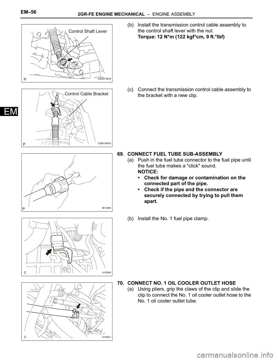
(b) Install the transmission control cable assembly to
the control shaft lever with the nut.
Torque: 12 N*m (122 kgf*cm, 9 ft.*lbf)
(c) Connect the transmission control cable assembly to
the bracket with a new clip.
69. CONNECT FUEL TUBE SUB-ASSEMBLY
(a) Push in the fuel tube connector to the fuel pipe until
the fuel tube makes a "click" sound.
NOTICE:
• Check for damage or contamination on the
connected part of the pipe.
• Check if the pipe and the connector are
securely connected by trying to pull them
apart.
(b) Install the No. 1 fuel pipe clamp.
70. CONNECT NO. 1 OIL COOLER OUTLET HOSE
(a) Using pliers, grip the claws of the clip and slide the
clip to connect the No. 1 oil cooler outlet hose to the
No. 1 oil cooler outlet tube.
D025414E04
C089134E02
B012944
A155045
A155031
Page 1163 of 3000
2GR-FE FUEL – FUEL TANKFU–43
FU
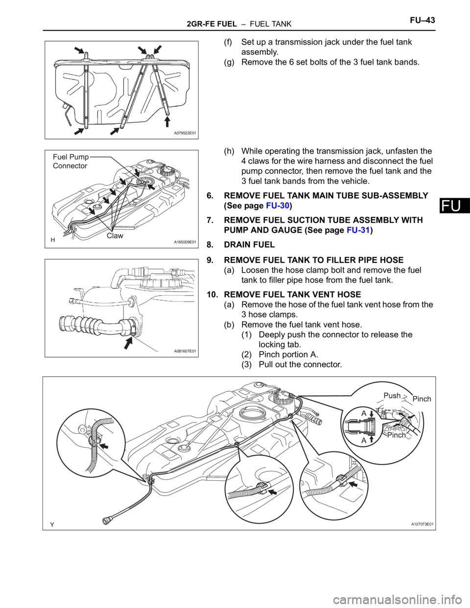
(f) Set up a transmission jack under the fuel tank
assembly.
(g) Remove the 6 set bolts of the 3 fuel tank bands.
(h) While operating the transmission jack, unfasten the
4 claws for the wire harness and disconnect the fuel
pump connector, then remove the fuel tank and the
3 fuel tank bands from the vehicle.
6. REMOVE FUEL TANK MAIN TUBE SUB-ASSEMBLY
(See page FU-30)
7. REMOVE FUEL SUCTION TUBE ASSEMBLY WITH
PUMP AND GAUGE (See page FU-31)
8. DRAIN FUEL
9. REMOVE FUEL TANK TO FILLER PIPE HOSE
(a) Loosen the hose clamp bolt and remove the fuel
tank to filler pipe hose from the fuel tank.
10. REMOVE FUEL TANK VENT HOSE
(a) Remove the hose of the fuel tank vent hose from the
3 hose clamps.
(b) Remove the fuel tank vent hose.
(1) Deeply push the connector to release the
locking tab.
(2) Pinch portion A.
(3) Pull out the connector.
A079522E01
A165009E01
A081607E01
A127073E01
Page 1166 of 3000
2GR-FE FUEL – FUEL TANKFU–43
FU
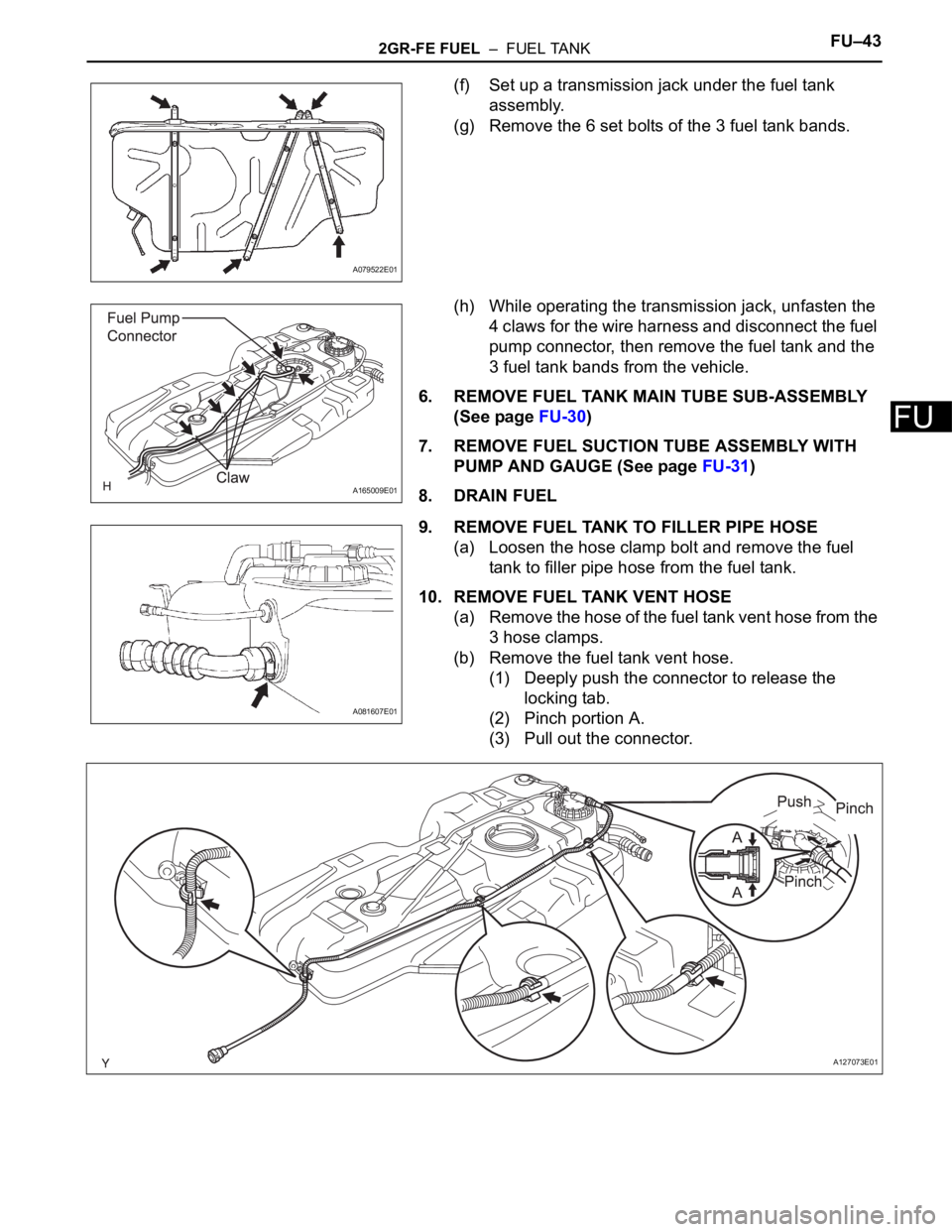
(f) Set up a transmission jack under the fuel tank
assembly.
(g) Remove the 6 set bolts of the 3 fuel tank bands.
(h) While operating the transmission jack, unfasten the
4 claws for the wire harness and disconnect the fuel
pump connector, then remove the fuel tank and the
3 fuel tank bands from the vehicle.
6. REMOVE FUEL TANK MAIN TUBE SUB-ASSEMBLY
(See page FU-30)
7. REMOVE FUEL SUCTION TUBE ASSEMBLY WITH
PUMP AND GAUGE (See page FU-31)
8. DRAIN FUEL
9. REMOVE FUEL TANK TO FILLER PIPE HOSE
(a) Loosen the hose clamp bolt and remove the fuel
tank to filler pipe hose from the fuel tank.
10. REMOVE FUEL TANK VENT HOSE
(a) Remove the hose of the fuel tank vent hose from the
3 hose clamps.
(b) Remove the fuel tank vent hose.
(1) Deeply push the connector to release the
locking tab.
(2) Pinch portion A.
(3) Pull out the connector.
A079522E01
A165009E01
A081607E01
A127073E01
Page 1167 of 3000

FU–442GR-FE FUEL – FUEL TANK
FU
INSTALLATION
1. CONNECT FUEL TANK VENT HOSE
2. INSTALL FUEL TANK TO FILLER PIPE HOSE
(a) Install a new fuel tank to filler pipe hose as shown in
the illustration.
3. INSTALL FUEL SUCTION TUBE ASSEMBLY WITH
PUMP AND GAUGE (See page FU-34)
4. INSTALL FUEL TANK MAIN TUBE SUB-ASSEMBLY
(See page FU-35)
5. INSTALL FUEL TANK ASSEMBLY
(a) Set up the fuel tank assembly to the transmission
jack.
(b) While operating the transmission jack, fasten the 4
claws for the wire harness and connect the fuel
pump connector, then install the fuel tank and the 3
fuel tank bands to the vehicle.
(c) Tighten the 6 set bolts of the 3 fuel tank bands.
Torque: 33 N*m (336 kgf*cm, 24 ft.*lbf)
(d) Install the 2 wire harness clamps.
(e) Connect the fuel tube.
(1) Push in the fuel tube connector to the pipe until
fuel tube connector makes "click" sound.
NOTICE:
• Check if there is any damage or foreign
objects on the connected part.
• After connecting, check if the connector
and the pipe are securely connected by
pulling on them.
A127074E02
A081610E01
Page 1170 of 3000

FU–442GR-FE FUEL – FUEL TANK
FU
INSTALLATION
1. CONNECT FUEL TANK VENT HOSE
2. INSTALL FUEL TANK TO FILLER PIPE HOSE
(a) Install a new fuel tank to filler pipe hose as shown in
the illustration.
3. INSTALL FUEL SUCTION TUBE ASSEMBLY WITH
PUMP AND GAUGE (See page FU-34)
4. INSTALL FUEL TANK MAIN TUBE SUB-ASSEMBLY
(See page FU-35)
5. INSTALL FUEL TANK ASSEMBLY
(a) Set up the fuel tank assembly to the transmission
jack.
(b) While operating the transmission jack, fasten the 4
claws for the wire harness and connect the fuel
pump connector, then install the fuel tank and the 3
fuel tank bands to the vehicle.
(c) Tighten the 6 set bolts of the 3 fuel tank bands.
Torque: 33 N*m (336 kgf*cm, 24 ft.*lbf)
(d) Install the 2 wire harness clamps.
(e) Connect the fuel tube.
(1) Push in the fuel tube connector to the pipe until
fuel tube connector makes "click" sound.
NOTICE:
• Check if there is any damage or foreign
objects on the connected part.
• After connecting, check if the connector
and the pipe are securely connected by
pulling on them.
A127074E02
A081610E01
Page 1247 of 3000

CO–322GR-FE COOLING – RADIATOR
CO
17. DISCONNECT NO. 2 OIL COOLER OUTLET TUBE
SUB-ASSEMBLY
(a) Disconnect the No. 1 oil cooler inlet and No. 1 oil
cooler outlet hoses from the No. 2 oil cooler outlet
tube sub-assembly.
(b) Disconnect the No. 1 transmission oil cooler hoses
from the radiator.
(c) Remove the 2 bolts and No. 2 oil cooler outlet tube
sub-assembly.
18. REMOVE HEADLIGHT ASSEMBLY RH
(a) Use the same procedures for the RH side and LH
side.
HINT:
See page LI-69
19. REMOVE RADIATOR SIDE DEFLECTOR RH
(a) Disengage the 3 claws and remove the radiator side
deflector RH.
A161467E02
A161464
Page 1261 of 3000

2GR-FE COOLING – RADIATORCO–43
CO
(b) Connect the No. 1 transmission oil cooler hoses to
the radiator.
(c) Connect the No. 1 oil cooler inlet and No. 1 oil
cooler outlet hoses to the No. 2 oil cooler outlet tube
sub-assembly.
13. INSTALL RADIATOR UPPER SUPPORT SUB-
ASSEMBLY
(a) Install the radiator upper support sub-assembly with
the 4 bolts.
Torque: 5.0 N*m (51 kgf*cm, 44 in.*lbf)
14. CONNECT COOLING FAN ECU CONNECTOR
(a) Connect the connector.
(b) Attach the clamp.
A161467E02
A161463
A161472E01
Page 1277 of 3000
CO–322GR-FE COOLING – RADIATOR
CO
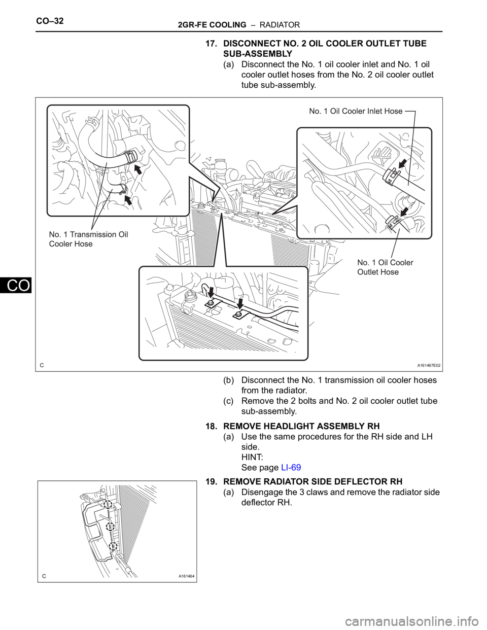
17. DISCONNECT NO. 2 OIL COOLER OUTLET TUBE
SUB-ASSEMBLY
(a) Disconnect the No. 1 oil cooler inlet and No. 1 oil
cooler outlet hoses from the No. 2 oil cooler outlet
tube sub-assembly.
(b) Disconnect the No. 1 transmission oil cooler hoses
from the radiator.
(c) Remove the 2 bolts and No. 2 oil cooler outlet tube
sub-assembly.
18. REMOVE HEADLIGHT ASSEMBLY RH
(a) Use the same procedures for the RH side and LH
side.
HINT:
See page LI-69
19. REMOVE RADIATOR SIDE DEFLECTOR RH
(a) Disengage the 3 claws and remove the radiator side
deflector RH.
A161467E02
A161464