TOYOTA SIENNA 2007 Service Repair Manual
Manufacturer: TOYOTA, Model Year: 2007, Model line: SIENNA, Model: TOYOTA SIENNA 2007Pages: 3000, PDF Size: 52.26 MB
Page 531 of 3000
2GR-FE ENGINE CONTROL SYSTEM – SFI SYSTEMES–225
ES
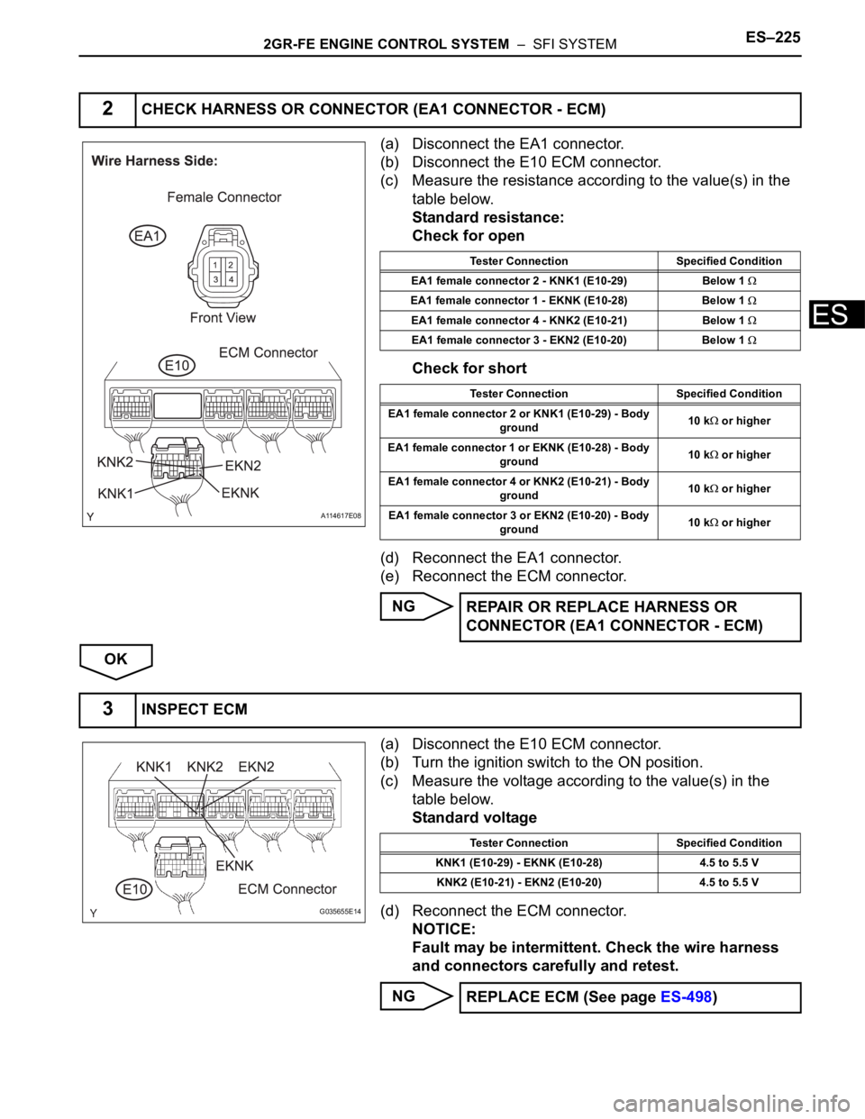
(a) Disconnect the EA1 connector.
(b) Disconnect the E10 ECM connector.
(c) Measure the resistance according to the value(s) in the
table below.
Standard resistance:
Check for open
Check for short
(d) Reconnect the EA1 connector.
(e) Reconnect the ECM connector.
NG
OK
(a) Disconnect the E10 ECM connector.
(b) Turn the ignition switch to the ON position.
(c) Measure the voltage according to the value(s) in the
table below.
Standard voltage
(d) Reconnect the ECM connector.
NOTICE:
Fault may be intermittent. Check the wire harness
and connectors carefully and retest.
NG
2CHECK HARNESS OR CONNECTOR (EA1 CONNECTOR - ECM)
A114617E08
Tester Connection Specified Condition
EA1 female connector 2 - KNK1 (E10-29) Below 1
EA1 female connector 1 - EKNK (E10-28) Below 1
EA1 female connector 4 - KNK2 (E10-21) Below 1
EA1 female connector 3 - EKN2 (E10-20) Below 1
Tester Connection Specified Condition
EA1 female connector 2 or KNK1 (E10-29) - Body
ground10 k
or higher
EA1 female connector 1 or EKNK (E10-28) - Body
ground10 k
or higher
EA1 female connector 4 or KNK2 (E10-21) - Body
ground10 k
or higher
EA1 female connector 3 or EKN2 (E10-20) - Body
ground10 k
or higher
REPAIR OR REPLACE HARNESS OR
CONNECTOR (EA1 CONNECTOR - ECM)
3INSPECT ECM
G035655E14
Tester Connection Specified Condition
KNK1 (E10-29) - EKNK (E10-28) 4.5 to 5.5 V
KNK2 (E10-21) - EKN2 (E10-20) 4.5 to 5.5 V
REPLACE ECM (See page ES-498)
Page 532 of 3000
ES–2262GR-FE ENGINE CONTROL SYSTEM – SFI SYSTEM
ES
OK
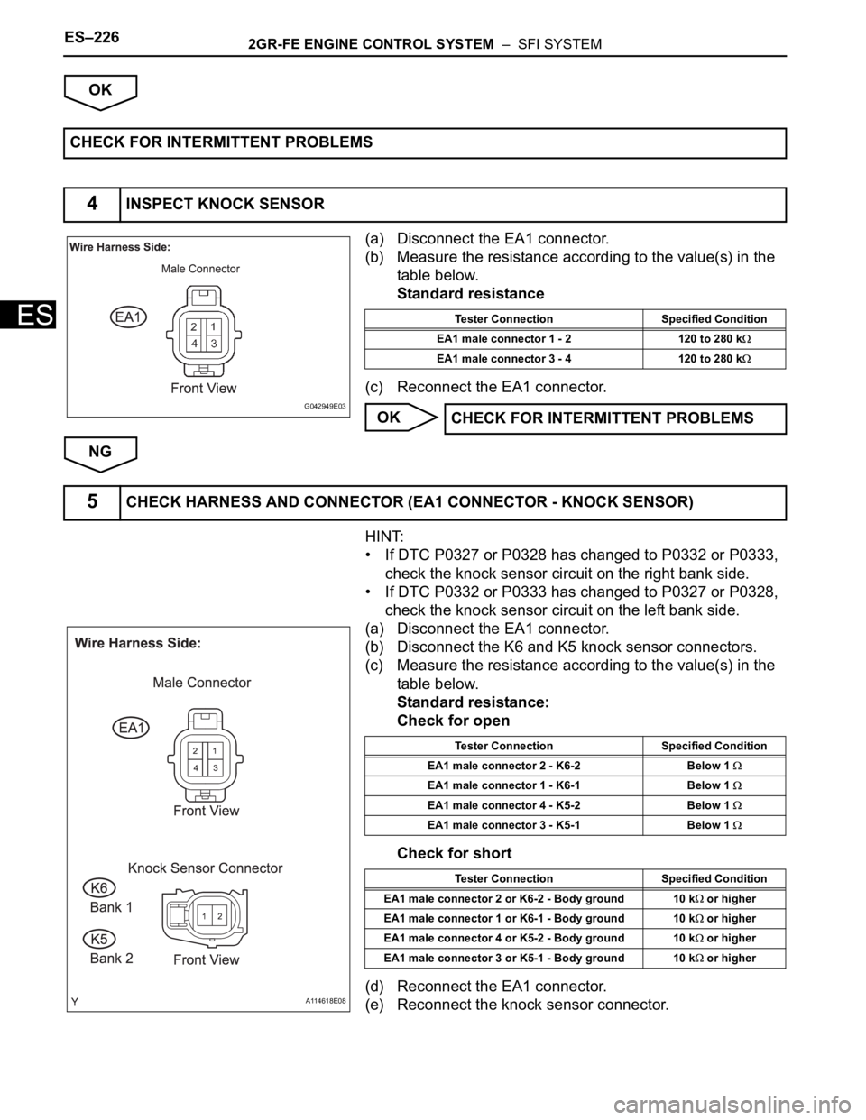
(a) Disconnect the EA1 connector.
(b) Measure the resistance according to the value(s) in the
table below.
Standard resistance
(c) Reconnect the EA1 connector.
OK
NG
HINT:
• If DTC P0327 or P0328 has changed to P0332 or P0333,
check the knock sensor circuit on the right bank side.
• If DTC P0332 or P0333 has changed to P0327 or P0328,
check the knock sensor circuit on the left bank side.
(a) Disconnect the EA1 connector.
(b) Disconnect the K6 and K5 knock sensor connectors.
(c) Measure the resistance according to the value(s) in the
table below.
Standard resistance:
Check for open
Check for short
(d) Reconnect the EA1 connector.
(e) Reconnect the knock sensor connector. CHECK FOR INTERMITTENT PROBLEMS
4INSPECT KNOCK SENSOR
G042949E03
Tester Connection Specified Condition
EA1 male connector 1 - 2 120 to 280 k
EA1 male connector 3 - 4 120 to 280 k
CHECK FOR INTERMITTENT PROBLEMS
5CHECK HARNESS AND CONNECTOR (EA1 CONNECTOR - KNOCK SENSOR)
A114618E08
Tester Connection Specified Condition
EA1 male connector 2 - K6-2 Below 1
EA1 male connector 1 - K6-1 Below 1
EA1 male connector 4 - K5-2 Below 1
EA1 male connector 3 - K5-1 Below 1
Tester Connection Specified Condition
EA1 male connector 2 or K6-2 - Body ground 10 k
or higher
EA1 male connector 1 or K6-1 - Body ground 10 k
or higher
EA1 male connector 4 or K5-2 - Body ground 10 k
or higher
EA1 male connector 3 or K5-1 - Body ground 10 k
or higher
Page 533 of 3000

2GR-FE ENGINE CONTROL SYSTEM – SFI SYSTEMES–227
ES
NG
OKREPAIR OR REPLACE HARNESS OR
CONNECTOR (EA1 CONNECTOR - KNOCK
SENSOR)
REPLACE KNOCK SENSOR (See page ES-520)
Page 534 of 3000
ES–2282GR-FE ENGINE CONTROL SYSTEM – SFI SYSTEM
ES
DESCRIPTION
The Crankshaft Position (CKP) sensor system consists of a CKP sensor plate and a pickup coil. The
sensor plate has 34 teeth and is installed on the crankshaft. The pickup coil is made of an iron core and a
magnet.
The sensor plate rotates as each tooth passes through the pickup coil, and a pulse signal is created. The
pickup coil generates 34 signals per engine revolution. Based on these signals, the ECM calculates the
crankshaft position and engine RPM. Using these calculations, the fuel injection time and ignition timing
are controlled.
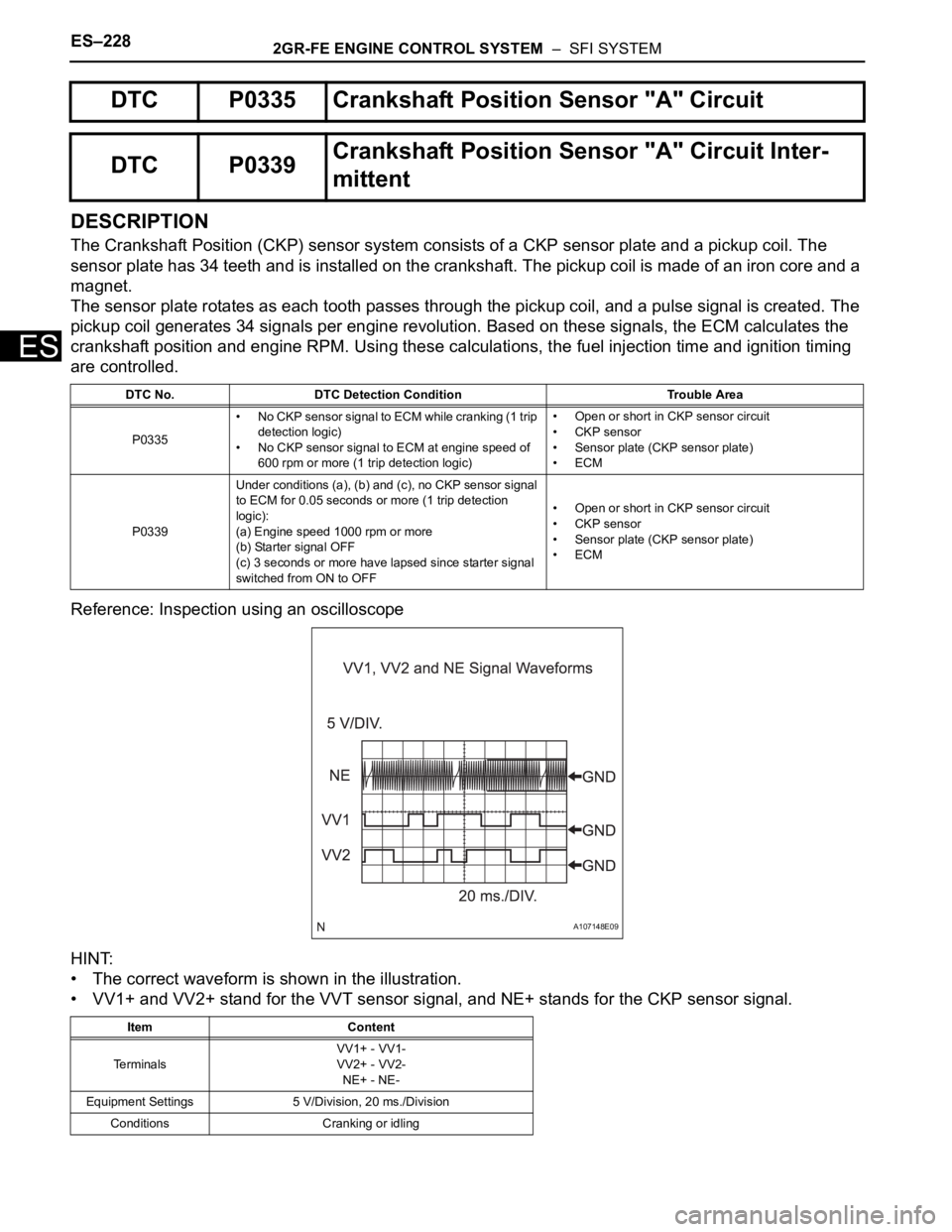
Reference: Inspection using an oscilloscope
HINT:
• The correct waveform is shown in the illustration.
• VV1+ and VV2+ stand for the VVT sensor signal, and NE+ stands for the CKP sensor signal.
DTC P0335 Crankshaft Position Sensor "A" Circuit
DTC P0339Crankshaft Position Sensor "A" Circuit Inter-
mittent
DTC No. DTC Detection Condition Trouble Area
P0335• No CKP sensor signal to ECM while cranking (1 trip
detection logic)
• No CKP sensor signal to ECM at engine speed of
600 rpm or more (1 trip detection logic)• Open or short in CKP sensor circuit
• CKP sensor
• Sensor plate (CKP sensor plate)
•ECM
P0339Under conditions (a), (b) and (c), no CKP sensor signal
to ECM for 0.05 seconds or more (1 trip detection
logic):
(a) Engine speed 1000 rpm or more
(b) Starter signal OFF
(c) 3 seconds or more have lapsed since starter signal
switched from ON to OFF• Open or short in CKP sensor circuit
• CKP sensor
• Sensor plate (CKP sensor plate)
•ECM
Item Content
Te r m i n a l sVV1+ - VV1-
VV2+ - VV2-
NE+ - NE-
Equipment Settings 5 V/Division, 20 ms./Division
Conditions Cranking or idling
A107148E09
Page 535 of 3000

2GR-FE ENGINE CONTROL SYSTEM – SFI SYSTEMES–229
ES
MONITOR DESCRIPTION
If there is no signal from the CKP sensor despite the engine revolving, the ECM interprets this as a
malfunction of the sensor.
If the malfunction is not repaired successfully, a DTC is set 10 seconds after the engine is next started.
MONITOR STRATEGY
TYPICAL ENABLING CONDITIONS
All:
Crankshaft Position Sensor Range Check during Cranking P0335:
Crankshaft Position Sensor Range Check during Engine Running P0335:
TYPICAL MALFUNCTION THRESHOLDS
Crankshaft Position Sensor Range Check during Cranking P0335:
Crankshaft Position Sensor Range Check during Engine Running P0335:
COMPONENT OPERATING RANGE
Related DTCsP0335: Crankshaft position sensor range check during cranking
P0335: Crankshaft position sensor range check during engine running
Required Sensors / Components (Main) Crankshaft Position (CKP) sensor
Required Sensors / Components (Related) -
Frequency of Operation Continuous
Duration 3 times
MIL Operation Immediate
Sequence of Operation None
The monitor will run whenever these DTCs are not
presentNone
Sta r t e r OF F
Ignition switch ON
Battery voltage 7 V or more
Minimum battery voltage while starter ON Less than 11 V
Number of VVT sensor signal pulse 6 times
CMP sensor circuit fail Not detected
Engine speed 600 rpm or more
Sta r t e r OF F
Time after starter from ON to OFF 3 seconds or more
Number of crankshaft position sensor signal pulse 132 or less, or 174 or more
CKP sensor signal No signal
CKP sensor• CKP sensor output voltage fluctuates while crankshaft is revolving
• 34 CKP sensor signals per crankshaft revolution
Page 536 of 3000
ES–2302GR-FE ENGINE CONTROL SYSTEM – SFI SYSTEM
ES
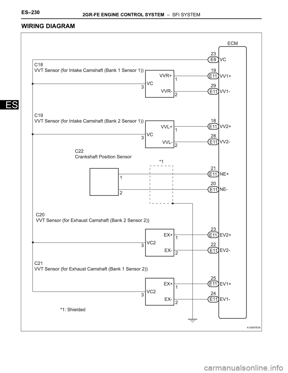
WIRING DIAGRAM
A136097E06
Page 537 of 3000
2GR-FE ENGINE CONTROL SYSTEM – SFI SYSTEMES–231
ES
INSPECTION PROCEDURE
HINT:
• If no problem is found by this diagnostic troubleshooting procedure, troubleshoot the engine
mechanical systems.
• Check the engine speed. The engine speed can be checked by using the intelligent tester. Perform the
following procedure:
(a) Connect the intelligent tester to the DLC3.
(b) Start the engine.
(c) Turn the tester on.
(d) Select the following menu items: DIAGNOSIS / ENHANCED OBD II / DATA LIST / PRIMARY /
ENGINE SPD.
The engine speed may be indicated as zero despite the engine revolving normally. This is caused
by a lack of NE signals from the Crankshaft Position (CKP) sensor. Alternatively, the engine speed
may be indicated as lower than the actual engine speed, if the CKP sensor voltage output is
insufficient.
• Read freeze frame data using the intelligent tester. The ECM records vehicle and driving condition
information as freeze frame data the moment a DTC is stored. When troubleshooting, freeze frame
data can be helpful in determining whether the vehicle was running or stopped, whether the engine
was warmed up or not, whether the air-fuel ratio was lean or rich, as well as other data recorded at the
time of a malfunction.
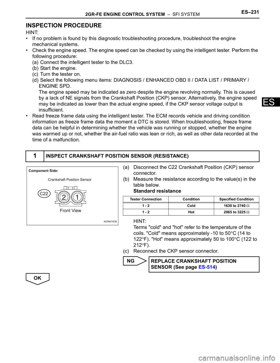
(a) Disconnect the C22 Crankshaft Position (CKP) sensor
connector.
(b) Measure the resistance according to the value(s) in the
table below.
Standard resistance
HINT:
Terms "cold" and "hot" refer to the temperature of the
coils. "Cold" means approximately -10 to 50
C (14 to
122
F). "Hot" means approximately 50 to 100C (122 to
212
F).
(c) Reconnect the CKP sensor connector.
NG
OK
1INSPECT CRANKSHAFT POSITION SENSOR (RESISTANCE)
A078431E26
Tester Connection Condition Specified Condition
1 - 2 Cold 1630 to 2740
1 - 2 Hot 2065 to 3225
REPLACE CRANKSHAFT POSITION
SENSOR (See page ES-514)
Page 538 of 3000
ES–2322GR-FE ENGINE CONTROL SYSTEM – SFI SYSTEM
ES
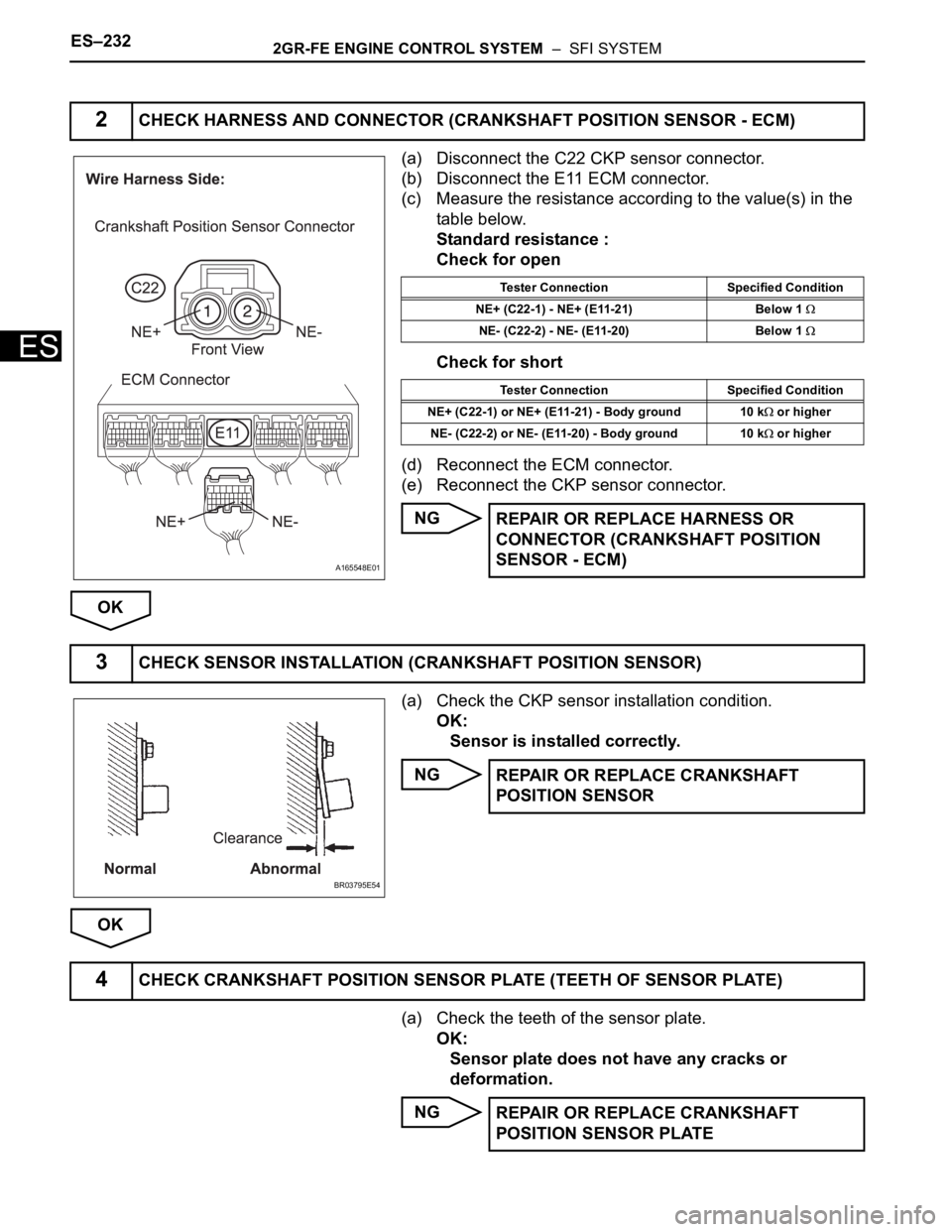
(a) Disconnect the C22 CKP sensor connector.
(b) Disconnect the E11 ECM connector.
(c) Measure the resistance according to the value(s) in the
table below.
Standard resistance :
Check for open
Check for short
(d) Reconnect the ECM connector.
(e) Reconnect the CKP sensor connector.
NG
OK
(a) Check the CKP sensor installation condition.
OK:
Sensor is installed correctly.
NG
OK
(a) Check the teeth of the sensor plate.
OK:
Sensor plate does not have any cracks or
deformation.
NG
2CHECK HARNESS AND CONNECTOR (CRANKSHAFT POSITION SENSOR - ECM)
A165548E01
Tester Connection Specified Condition
NE+ (C22-1) - NE+ (E11-21) Below 1
NE- (C22-2) - NE- (E11-20) Below 1
Tester Connection Specified Condition
NE+ (C22-1) or NE+ (E11-21) - Body ground 10 k
or higher
NE- (C22-2) or NE- (E11-20) - Body ground 10 k
or higher
REPAIR OR REPLACE HARNESS OR
CONNECTOR (CRANKSHAFT POSITION
SENSOR - ECM)
3CHECK SENSOR INSTALLATION (CRANKSHAFT POSITION SENSOR)
BR03795E54
REPAIR OR REPLACE CRANKSHAFT
POSITION SENSOR
4CHECK CRANKSHAFT POSITION SENSOR PLATE (TEETH OF SENSOR PLATE)
REPAIR OR REPLACE CRANKSHAFT
POSITION SENSOR PLATE
Page 539 of 3000

2GR-FE ENGINE CONTROL SYSTEM – SFI SYSTEMES–233
ES
OK
REPLACE ECM (See page ES-498)
Page 540 of 3000

ES–2342GR-FE ENGINE CONTROL SYSTEM – SFI SYSTEM
ES
DESCRIPTION
The intake camshaft's Variable Valve Timing (VVT) sensor (G signal) consists of a magnet and MRE
(Magneto Resistance Element).
The VVT camshaft drive gear has a sensor plate with 3 teeth on its outer circumference. When the gear
rotates, changes occur in the air gaps between the sensor plate and MRE, which affects the magnetic
field. As a result, the resistance of the MRE material fluctuates. The VVT sensor converts the gear
rotation data to pulse signals, uses the pulse signals to determine the camshaft angle, and sends it to the
ECM.
The crankshaft angle sensor plate has 34 teeth. The pickup coil generates 34 signals for each engine
revolution. Based on combination of the G signal and NE signal, the ECM detects the crankshaft angle.
Then the ECM uses this data to control fuel injection time and injection timing. Also, based on the NE
signal, the ECM detects the engine speed.
Reference: Inspection using an oscilloscope
DTC P0340Camshaft Position Sensor "A" Circuit (Bank 1
or Single Sensor)
DTC P0342Camshaft Position Sensor "A" Circuit Low
Input (Bank 1 or Single Sensor)
DTC P0343Camshaft Position Sensor "A" Circuit High
Input (Bank 1 or Single Sensor)
DTC P0345 Camshaft Position Sensor "A" Circuit (Bank 2)
DTC P0347Camshaft Position Sensor "A" Circuit Low
Input (Bank 2)
DTC P0348Camshaft Position Sensor "A" Circuit High
Input (Bank 2)
DTC No. DTC Detection Condition Trouble Area
P0340
P0345• Input voltage to ECM remains 0.3 V or less, or 4.7
V or higher for more than 5 seconds, when 2 or
more seconds have elapsed after turning ignition
switch ON (2 trip detection logic)
• No VVT sensor signal to ECM during cranking (1
trip detection logic)• Open or short in VVT sensor circuit for intake
camshaft
• VVT sensor for intake camshaft
• Camshaft timing gear for intake camshaft
• Jumped tooth of timing chain for intake camshaft
•ECM
P0342
P0347Output voltage of VVT sensor is 0.3 V or less for 5
seconds (1 trip detection logic)• Open or short in VVT sensor circuit for intake
camshaft
• VVT sensor for intake camshaft
• Camshaft timing gear for intake camshaft
• Jumped tooth of timing chain for intake camshaft
•ECM
P0343
P0348Output voltage of VVT sensor is 4.7 V or more for 5
seconds (1 trip detection logic)• Open or short in VVT sensor circuit for intake
camshaft
• VVT sensor for intake camshaft
• Camshaft timing gear for intake camshaft
• Jumped tooth of timing chain for intake camshaft
•ECM