TOYOTA SIENNA 2007 Service Repair Manual
Manufacturer: TOYOTA, Model Year: 2007, Model line: SIENNA, Model: TOYOTA SIENNA 2007Pages: 3000, PDF Size: 52.26 MB
Page 541 of 3000
2GR-FE ENGINE CONTROL SYSTEM – SFI SYSTEMES–235
ES
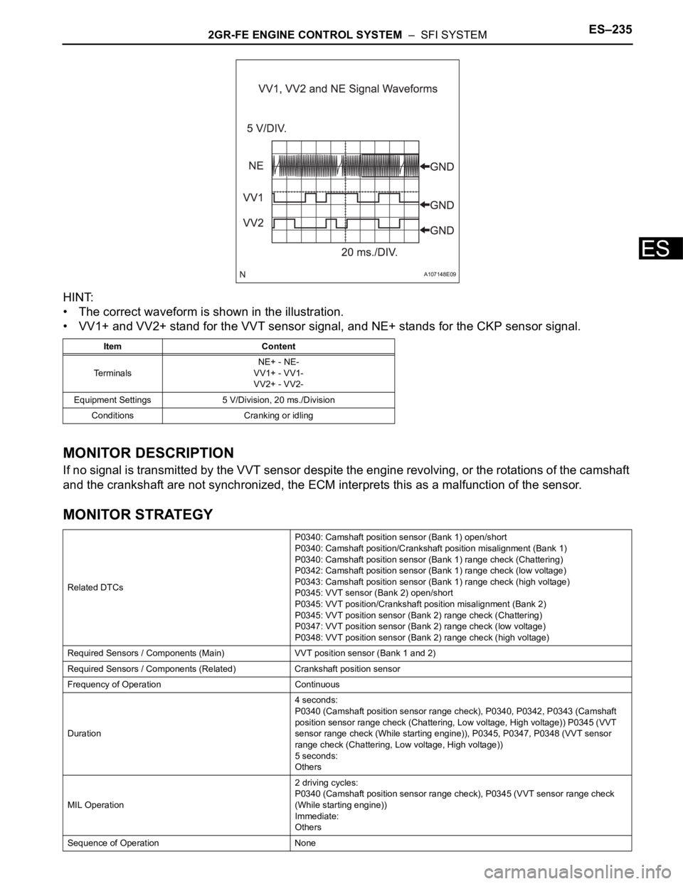
HINT:
• The correct waveform is shown in the illustration.
• VV1+ and VV2+ stand for the VVT sensor signal, and NE+ stands for the CKP sensor signal.
MONITOR DESCRIPTION
If no signal is transmitted by the VVT sensor despite the engine revolving, or the rotations of the camshaft
and the crankshaft are not synchronized, the ECM interprets this as a malfunction of the sensor.
MONITOR STRATEGY
Item Content
TerminalsNE+ - NE-
VV1+ - VV1-
VV2+ - VV2-
Equipment Settings 5 V/Division, 20 ms./Division
Conditions Cranking or idling
Related DTCsP0340: Camshaft position sensor (Bank 1) open/short
P0340: Camshaft position/Crankshaft position misalignment (Bank 1)
P0340: Camshaft position sensor (Bank 1) range check (Chattering)
P0342: Camshaft position sensor (Bank 1) range check (low voltage)
P0343: Camshaft position sensor (Bank 1) range check (high voltage)
P0345: VVT sensor (Bank 2) open/short
P0345: VVT position/Crankshaft position misalignment (Bank 2)
P0345: VVT position sensor (Bank 2) range check (Chattering)
P0347: VVT position sensor (Bank 2) range check (low voltage)
P0348: VVT position sensor (Bank 2) range check (high voltage)
Required Sensors / Components (Main) VVT position sensor (Bank 1 and 2)
Required Sensors / Components (Related) Crankshaft position sensor
Frequency of Operation Continuous
Duration4 seconds:
P0340 (Camshaft position sensor range check), P0340, P0342, P0343 (Camshaft
position sensor range check (Chattering, Low voltage, High voltage)) P0345 (VVT
sensor range check (While starting engine)), P0345, P0347, P0348 (VVT sensor
range check (Chattering, Low voltage, High voltage))
5 seconds:
Others
MIL Operation2 driving cycles:
P0340 (Camshaft position sensor range check), P0345 (VVT sensor range check
(While starting engine))
Immediate:
Others
Sequence of Operation None
A107148E09
Page 542 of 3000

ES–2362GR-FE ENGINE CONTROL SYSTEM – SFI SYSTEM
ES
TYPICAL ENABLING CONDITIONS
All:
Camshaft Position Sensor Range Check:
Camshaft Position/Crankshaft Position Misalignment:
Camshaft Position Sensor Range Check (Chattering, Low voltage, High voltage):
VVT sensor range check (While starting engine):
VVT sensor range check (After starting engine):
VVT sensor range check (Chattering, Low voltage, High voltage):
TYPICAL MALFUNCTION THRESHOLDS
Camshaft Position Sensor Range Check:
Camshaft Position/Crankshaft Position Misalignment:
Camshaft Position Sensor Range Check (Fluctuating):
Camshaft Position Sensor Range Check (Low voltage):
Camshaft Position Sensor Range Check (High voltage):
VVT sensor range check (While starting engine):
VVT sensor range check (After starting engine):
The monitor will run whenever these DTCs are not
presentNone
Starter ON and not starter ON again
Minimal battery voltage while starter ON Less than 11 V
Engine RPM 600 rpm or more
Starter OFF
Starter OFF
Ignition switch ON and time after ignition switch is OFF
to ON2 seconds or more
Starter ON
Battery voltage while starter ON once at least Less than 11 V
Engine RPM 600 rpm or more
Starter OFF
Battery voltage 8 V or more
Ignition switch ON
Starter OFF
Ignition switch ON and time after ignition switch is OFF
to ON2 seconds or more
Battery voltage 8 V or more
Camshaft position signal No signal
Camshaft position and crankshaft position phase Mis-aligned
Camshaft position voltage Less than 0.3 V, or more than 4.7 V
Camshaft position voltage Less than 0.3 V
Camshaft position voltage More than 4.7 V
VVT sensor signal No signal
VVT sensor signal No signal
Page 543 of 3000
2GR-FE ENGINE CONTROL SYSTEM – SFI SYSTEMES–237
ES
VVT sensor range check (Fluctuating):
VVT sensor range check (Low voltage):
VVT sensor range check (High voltage):
COMPONENT OPERATING RANGE
WIRING DIAGRAM
Refer to DTC P0335 (See page ES-222).
INSPECTION PROCEDURE
HINT:
Read freeze frame data using the intelligent tester. The ECM records vehicle and driving condition
information as freeze frame data the moment a DTC is stored. When troubleshooting, freeze frame data
can be helpful in determining whether the vehicle was running or stopped, whether the engine was
warmed up or not, whether the air-fuel ratio was lean or rich, as well as other data recorded at the time of
a malfunction.
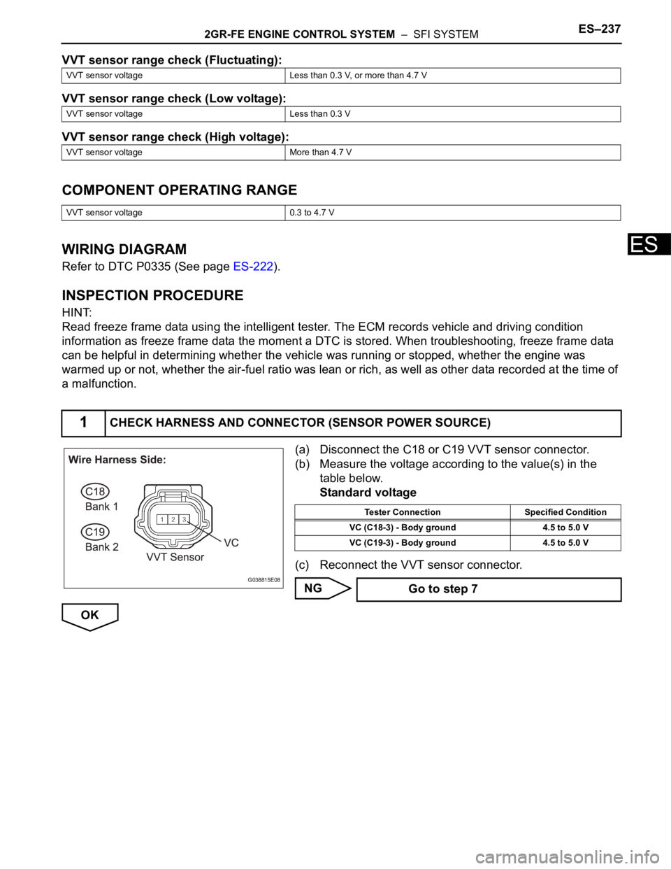
(a) Disconnect the C18 or C19 VVT sensor connector.
(b) Measure the voltage according to the value(s) in the
table below.
Standard voltage
(c) Reconnect the VVT sensor connector.
NG
OK
VVT sensor voltage Less than 0.3 V, or more than 4.7 V
VVT sensor voltage Less than 0.3 V
VVT sensor voltage More than 4.7 V
VVT sensor voltage 0.3 to 4.7 V
1CHECK HARNESS AND CONNECTOR (SENSOR POWER SOURCE)
G038815E08
Tester Connection Specified Condition
VC (C18-3) - Body ground 4.5 to 5.0 V
VC (C19-3) - Body ground 4.5 to 5.0 V
Go to step 7
Page 544 of 3000
ES–2382GR-FE ENGINE CONTROL SYSTEM – SFI SYSTEM
ES
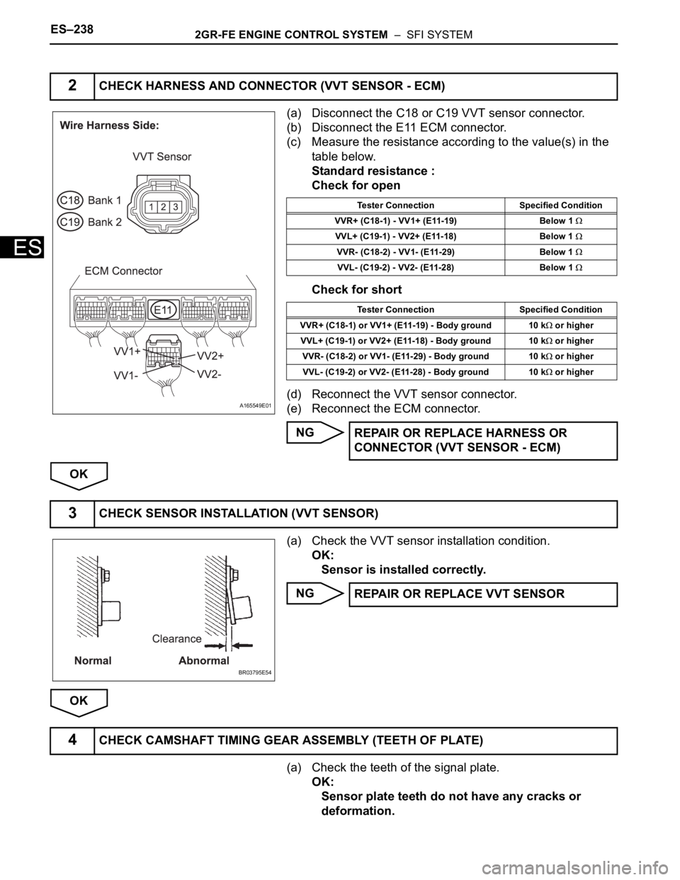
(a) Disconnect the C18 or C19 VVT sensor connector.
(b) Disconnect the E11 ECM connector.
(c) Measure the resistance according to the value(s) in the
table below.
Standard resistance :
Check for open
Check for short
(d) Reconnect the VVT sensor connector.
(e) Reconnect the ECM connector.
NG
OK
(a) Check the VVT sensor installation condition.
OK:
Sensor is installed correctly.
NG
OK
(a) Check the teeth of the signal plate.
OK:
Sensor plate teeth do not have any cracks or
deformation.
2CHECK HARNESS AND CONNECTOR (VVT SENSOR - ECM)
A165549E01
Tester Connection Specified Condition
VVR+ (C18-1) - VV1+ (E11-19) Below 1
VVL+ (C19-1) - VV2+ (E11-18) Below 1
VVR- (C18-2) - VV1- (E11-29) Below 1
VVL- (C19-2) - VV2- (E11-28) Below 1
Tester Connection Specified Condition
VVR+ (C18-1) or VV1+ (E11-19) - Body ground 10 k
or higher
VVL+ (C19-1) or VV2+ (E11-18) - Body ground 10 k
or higher
VVR- (C18-2) or VV1- (E11-29) - Body ground 10 k
or higher
VVL- (C19-2) or VV2- (E11-28) - Body ground 10 k
or higher
REPAIR OR REPLACE HARNESS OR
CONNECTOR (VVT SENSOR - ECM)
3CHECK SENSOR INSTALLATION (VVT SENSOR)
BR03795E54
REPAIR OR REPLACE VVT SENSOR
4CHECK CAMSHAFT TIMING GEAR ASSEMBLY (TEETH OF PLATE)
Page 545 of 3000
2GR-FE ENGINE CONTROL SYSTEM – SFI SYSTEMES–239
ES
NG
OK
(a) Replace the VVT sensor (See page ES-509).
NEXT
(a) Connect the intelligent tester to the DLC3.
(b) Turn the ignition switch to the ON position.
(c) Turn the intelligent tester on.
(d) Clear the DTCs.
(e) Select the following menu items: DIAGNOSIS /
ENHANCED OBD II / DTC / INFO / PENDING CODES.
(f) Read the DTCs.
Result
HINT:
If the engine does not start, replace the ECM.
B
AREPLACE CAMSHAFT TIMING GEAR
ASSEMBLY
5REPLACE VVT SENSOR
6CHECK WHETHER DTC OUTPUT RECURS
Display (DTC Output) Proceed to
No output A
P0340, P0342, P0343, P0345, P0347 or P0348 B
REPLACE ECM (See page ES-498)
END
Page 546 of 3000
ES–2402GR-FE ENGINE CONTROL SYSTEM – SFI SYSTEM
ES
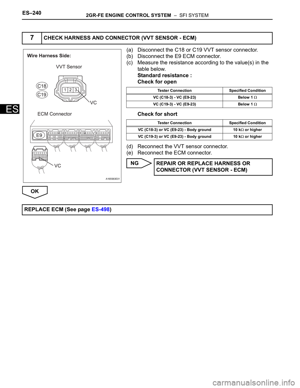
(a) Disconnect the C18 or C19 VVT sensor connector.
(b) Disconnect the E9 ECM connector.
(c) Measure the resistance according to the value(s) in the
table below.
Standard resistance :
Check for open
Check for short
(d) Reconnect the VVT sensor connector.
(e) Reconnect the ECM connector.
NG
OK
7CHECK HARNESS AND CONNECTOR (VVT SENSOR - ECM)
A165583E01
Tester Connection Specified Condition
VC (C18-3) - VC (E9-23) Below 1
VC (C19-3) - VC (E9-23) Below 1
Tester Connection Specified Condition
VC (C18-3) or VC (E9-23) - Body ground 10 k
or higher
VC (C19-3) or VC (E9-23) - Body ground 10 k
or higher
REPAIR OR REPLACE HARNESS OR
CONNECTOR (VVT SENSOR - ECM)
REPLACE ECM (See page ES-498)
Page 547 of 3000

2GR-FE ENGINE CONTROL SYSTEM – SFI SYSTEMES–241
ES
HINT:
• These DTCs indicate malfunctions relating to the primary circuit.
• If DTC P0351 is set, check the No. 1 ignition coil with igniter circuit.
• If DTC P0352 is set, check the No. 2 ignition coil with igniter circuit.
• If DTC P0353 is set, check the No. 3 ignition coil with igniter circuit.
• If DTC P0354 is set, check the No. 4 ignition coil with igniter circuit.
• If DTC P0355 is set, check the No. 5 ignition coil with igniter circuit.
• If DTC P0356 is set, check the No. 6 ignition coil with igniter circuit.
DESCRIPTION
A Direct Ignition System (DIS) is used on this vehicle.
The DIS is a 1-cylinder ignition system in which each cylinder is ignited by one ignition coil and one spark
plug is connected to the end of each secondary wiring. High-voltage is generated in the secondary wiring
and then applied directly to each spark plug. The sparks of the spark plugs pass from the center
electrodes to the ground electrodes.
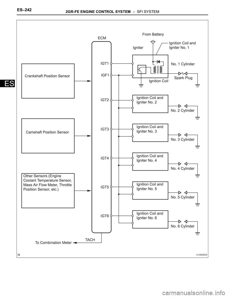
The ECM determines the ignition timing and transmits the ignition (IGT) signals to each cylinder. Using the
IGT signal, the ECM turns the power transistor inside the igniter on and off. The power transistor, in turn,
switches on and off the current to the primary coil. When the current to the primary coil is cut off, high-
voltage is generated in the secondary coil. This voltage is applied to the spark plugs, causing them to
spark inside the cylinders. As the ECM cuts the current to the primary coil off, the igniter sends back an
ignition confirmation (IGF) signal to the ECM, for each cylinder ignition.
DTC P0351 Ignition Coil "A" Primary / Secondary Circuit
DTC P0352 Ignition Coil "B" Primary / Secondary Circuit
DTC P0353 Ignition Coil "C" Primary / Secondary Circuit
DTC P0354 Ignition Coil "D" Primary / Secondary Circuit
DTC P0355 Ignition Coil "E" Primary / Secondary Circuit
DTC P0356 Ignition Coil "F" Primary / Secondary Circuit
Page 548 of 3000
ES–2422GR-FE ENGINE CONTROL SYSTEM – SFI SYSTEM
ES
A133853E05
Page 549 of 3000
2GR-FE ENGINE CONTROL SYSTEM – SFI SYSTEMES–243
ES
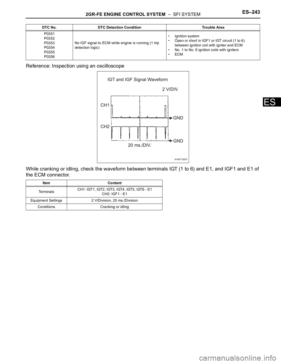
Reference: Inspection using an oscilloscope
While cranking or idling, check the waveform between terminals IGT (1 to 6) and E1, and IGF1 and E1 of
the ECM connector.
DTC No. DTC Detection Condition Trouble Area
P0351
P0352
P0353
P0354
P0355
P0356No IGF signal to ECM while engine is running (1 trip
detection logic)• Ignition system
• Open or short in IGF1 or IGT circuit (1 to 6)
between ignition coil with igniter and ECM
• No. 1 to No. 6 ignition coils with igniters
•ECM
Item Content
TerminalsCH1: IGT1, IGT2, IGT3, IGT4, IGT5, IGT6 - E1
CH2: IGF1 - E1
Equipment Settings 2 V/Division, 20 ms./Division
Conditions Cranking or idling
A140712E01
Page 550 of 3000
ES–2442GR-FE ENGINE CONTROL SYSTEM – SFI SYSTEM
ES
MONITOR DESCRIPTION
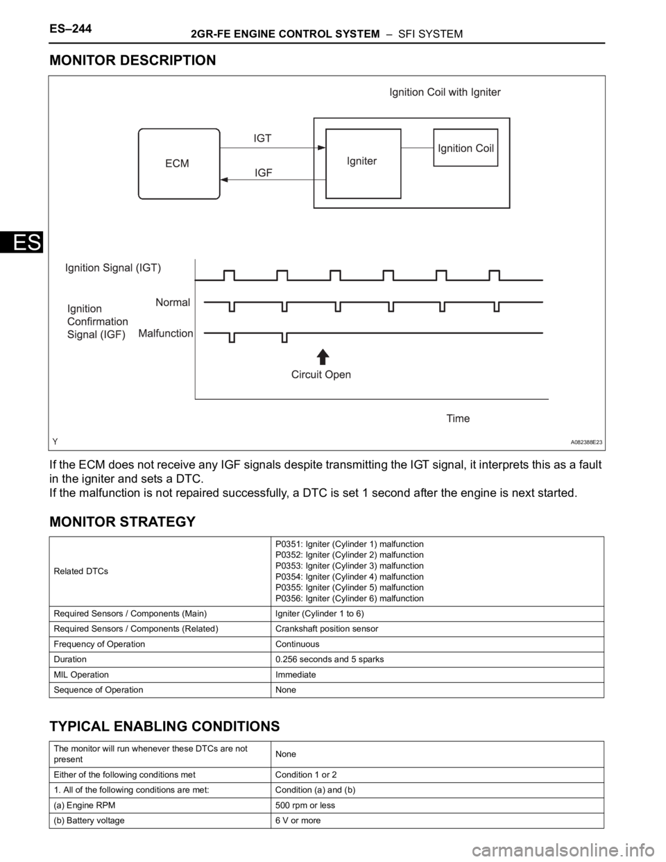
If the ECM does not receive any IGF signals despite transmitting the IGT signal, it interprets this as a fault
in the igniter and sets a DTC.
If the malfunction is not repaired successfully, a DTC is set 1 second after the engine is next started.
MONITOR STRATEGY
TYPICAL ENABLING CONDITIONS
Related DTCsP0351: Igniter (Cylinder 1) malfunction
P0352: Igniter (Cylinder 2) malfunction
P0353: Igniter (Cylinder 3) malfunction
P0354: Igniter (Cylinder 4) malfunction
P0355: Igniter (Cylinder 5) malfunction
P0356: Igniter (Cylinder 6) malfunction
Required Sensors / Components (Main) Igniter (Cylinder 1 to 6)
Required Sensors / Components (Related) Crankshaft position sensor
Frequency of Operation Continuous
Duration 0.256 seconds and 5 sparks
MIL Operation Immediate
Sequence of Operation None
The monitor will run whenever these DTCs are not
presentNone
Either of the following conditions met Condition 1 or 2
1. All of the following conditions are met: Condition (a) and (b)
(a) Engine RPM 500 rpm or less
(b) Battery voltage 6 V or more
A082388E23