TOYOTA SIENNA 2007 Service Repair Manual
Manufacturer: TOYOTA, Model Year: 2007, Model line: SIENNA, Model: TOYOTA SIENNA 2007Pages: 3000, PDF Size: 52.26 MB
Page 691 of 3000

ES–3982GR-FE ENGINE CONTROL SYSTEM – SFI SYSTEM
ES
TYPICAL MALFUNCTION THRESHOLDS
MONITOR RESULT
Refer to CHECKING MONITOR STATUS (See page ES-19).
WIRING DIAGRAM
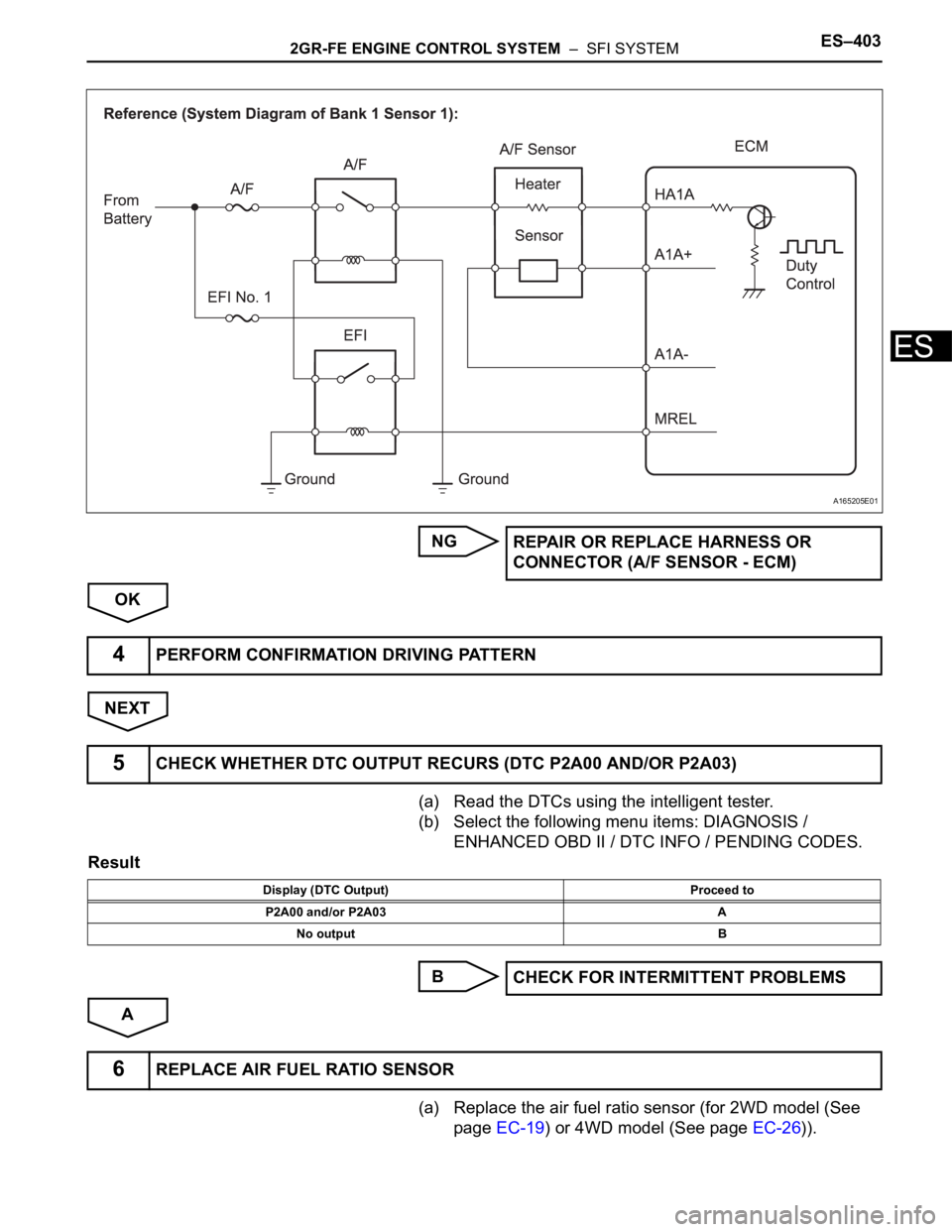
Refer to DTC P2195 (See page ES-359).
INSPECTION PROCEDURE
HINT:
Malfunctioning areas can be identified by performing the A/F CONTROL function provided in the ACTIVE
TEST. The A/F CONTROL function can help to determine whether the Air-Fuel Ratio (A/F) sensor, Heated
Oxygen (HO2) sensor and other potential trouble areas are malfunctioning.
The following instructions describe how to conduct the A/F CONTROL operation using an intelligent
tester.
(a) Connect the intelligent tester to the DLC3.
(b) Start the engine and turn the tester on.
(c) Warm up the engine at an engine speed of 2500 rpm for approximately 90 seconds.
(d) Select the following menu items on the tester: DIAGNOSIS / ENHANCED OBD II / ACTIVE TEST / A/
F CONTROL.
(e) Perform the A/F CONTROL operation with the engine in an idling condition (press the RIGHT or LEFT
button to change the fuel injection volume).
(f) Monitor the voltage outputs of the A/F and HO2 sensors (AFS B1S1 and O2S B1S2 or AFS B2S1 and
O2S B2S2) displayed on the tester.
HINT:
• The A/F CONTROL operation lowers the fuel injection volume by 12.5% or increases the injection
volume by 25%.
• Each sensor reacts in accordance with increases and decreases in the fuel injection volume.
Standard voltage
NOTICE:
The Air-Fuel Ratio (A/F) sensor has an output delay of a few seconds and the Heated Oxygen
(HO2) sensor has a maximum output delay of approximately 20 seconds.
Shift position 2 or more
Catalyst monitor Not yet
MAF 2.5 to 15 g/s
Response rate deterioration level Less than 0.18 V
Tester Display (Sensor) Injection Volumes Status Voltages
AFS B1S1 or AFS B2S1 (A/F) +25% Rich Less than 3.0
AFS B1S1 or AFS B2S1 (A/F) -12.5% Lean More than 3.35
O2S B1S2 or O2S B2S2 (HO2) +25% Rich More than 0.55
O2S B1S2 or O2S B2S2 (HO2) -12.5% Lean Less than 0.4
Page 692 of 3000
2GR-FE ENGINE CONTROL SYSTEM – SFI SYSTEMES–399
ES
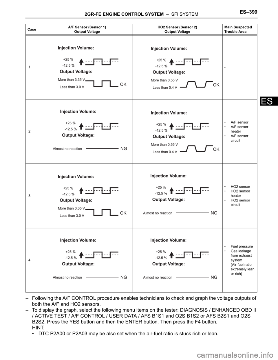
– Following the A/F CONTROL procedure enables technicians to check and graph the voltage outputs of
both the A/F and HO2 sensors.
– To display the graph, select the following menu items on the tester: DIAGNOSIS / ENHANCED OBD II
/ ACTIVE TEST / A/F CONTROL / USER DATA / AFS B1S1 and O2S B1S2 or AFS B2S1 and O2S
B2S2. Press the YES button and then the ENTER button. Then press the F4 button.
HINT:
• DTC P2A00 or P2A03 may be also set when the air-fuel ratio is stuck rich or lean.
CaseA/F Sensor (Sensor 1)
Output VoltageHO2 Sensor (Sensor 2)
Output VoltageMain Suspected
Trouble Area
1-
2•A/F sensor
•A/F sensor
heater
•A/F sensor
circuit
3•HO2 sensor
• HO2 sensor
heater
• HO2 sensor
circuit
4• Fuel pressure
• Gas leakage
from exhaust
system
(Air-fuel ratio
extremely lean
or rich)
Page 693 of 3000
ES–4002GR-FE ENGINE CONTROL SYSTEM – SFI SYSTEM
ES
• A low A/F sensor voltage could be caused by a rich air-fuel mixture. Check for conditions that would
cause the engine to run rich.
• A high A/F sensor voltage could be caused by a lean air-fuel mixture. Check for conditions that
would cause the engine to run lean.
• Read freeze frame data using the intelligent tester. The ECM records vehicle and driving condition
information as freeze frame data the moment a DTC is stored. When troubleshooting, freeze frame
data can be helpful in determining whether the vehicle was running or stopped, whether the engine
was warmed up or not, whether the air-fuel ratio was lean or rich, as well as other data recorded at
the time of a malfunction.
(a) Connect the intelligent tester to the DLC3.
(b) Turn the ignition switch to the ON position.
(c) Turn the tester on.
(d) Select the following menu items: DIAGNOSIS /
ENHANCED OBD II / DTC INFO / CURRENT CODES.
(e) Read the DTCs.
Result
HINT:
If any DTCs other than P2A00 or P2A03 are output,
troubleshoot those DTCs first.
B
A
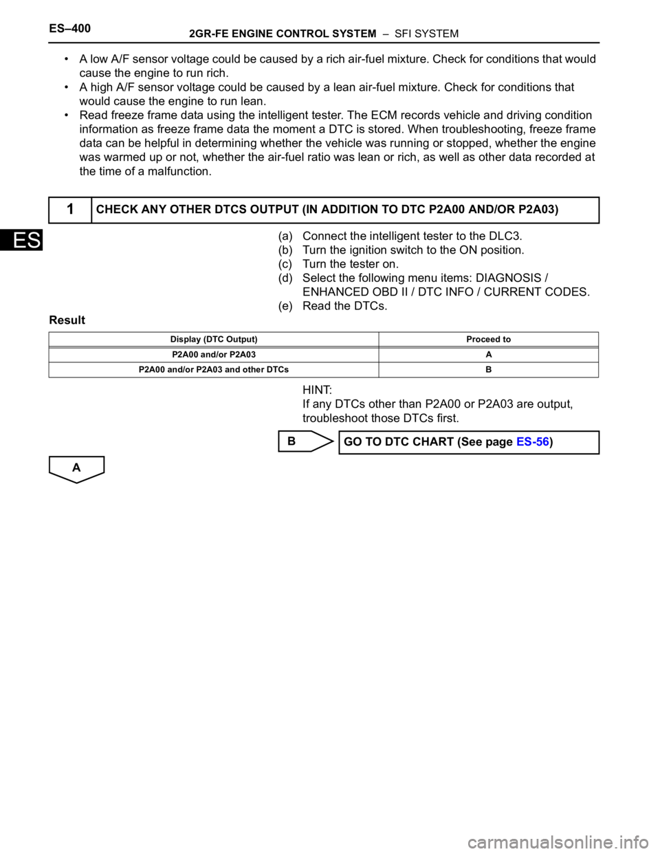
1CHECK ANY OTHER DTCS OUTPUT (IN ADDITION TO DTC P2A00 AND/OR P2A03)
Display (DTC Output) Proceed to
P2A00 and/or P2A03 A
P2A00 and/or P2A03 and other DTCs B
GO TO DTC CHART (See page ES-56)
Page 694 of 3000
2GR-FE ENGINE CONTROL SYSTEM – SFI SYSTEMES–401
ES
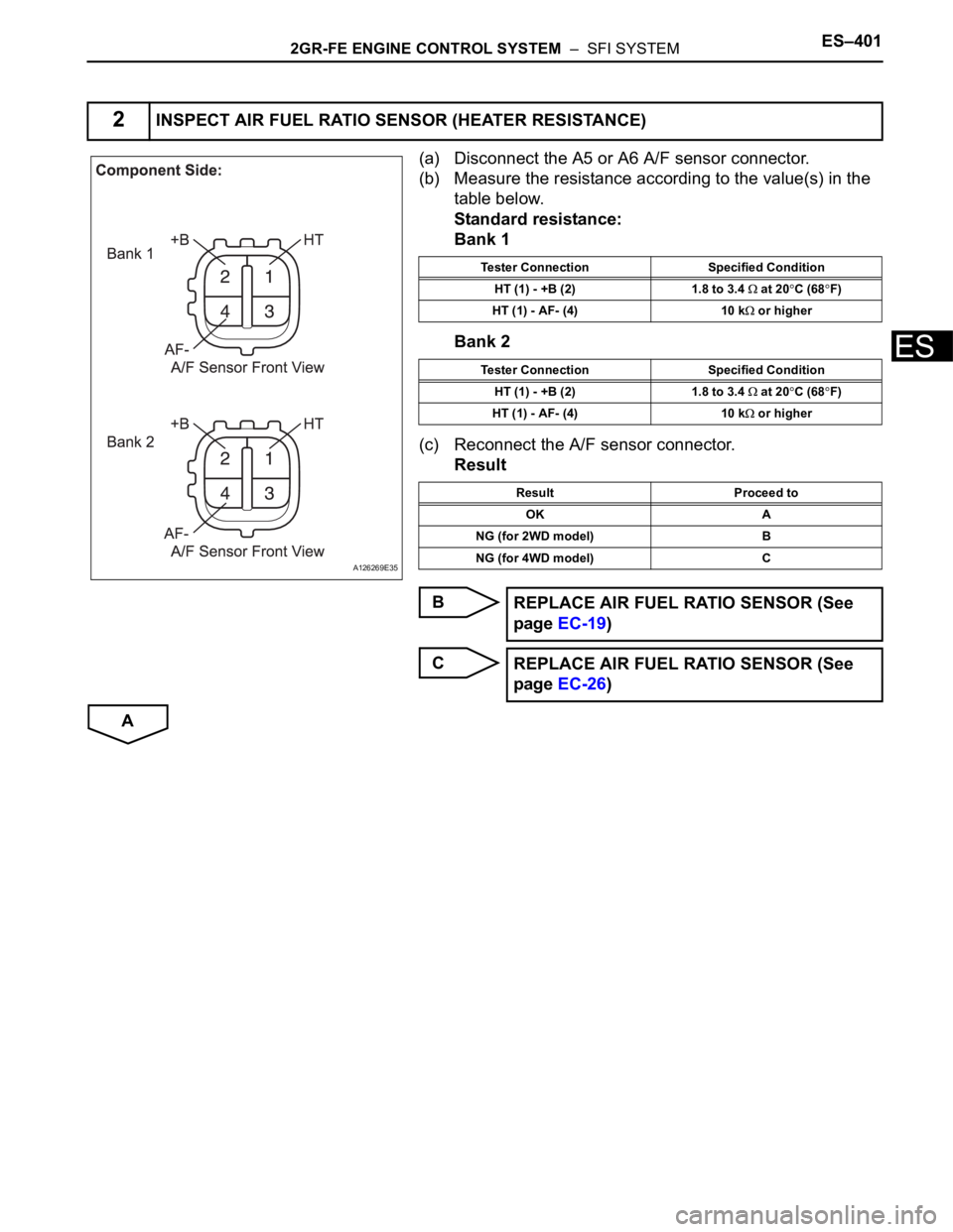
(a) Disconnect the A5 or A6 A/F sensor connector.
(b) Measure the resistance according to the value(s) in the
table below.
Standard resistance:
Bank 1
Bank 2
(c) Reconnect the A/F sensor connector.
Result
B
C
A
2INSPECT AIR FUEL RATIO SENSOR (HEATER RESISTANCE)
A126269E35
Tester Connection Specified Condition
HT (1) - +B (2) 1.8 to 3.4
at 20C (68F)
HT (1) - AF- (4) 10 k
or higher
Tester Connection Specified Condition
HT (1) - +B (2) 1.8 to 3.4
at 20C (68F)
HT (1) - AF- (4) 10 k
or higher
Result Proceed to
OK A
NG (for 2WD model) B
NG (for 4WD model) C
REPLACE AIR FUEL RATIO SENSOR (See
page EC-19)
REPLACE AIR FUEL RATIO SENSOR (See
page EC-26)
Page 695 of 3000
ES–4022GR-FE ENGINE CONTROL SYSTEM – SFI SYSTEM
ES
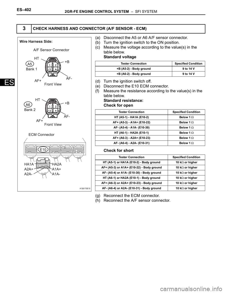
(a) Disconnect the A5 or A6 A/F sensor connector.
(b) Turn the ignition switch to the ON position.
(c) Measure the voltage according to the value(s) in the
table below.
Standard voltage
(d) Turn the ignition switch off.
(e) Disconnect the E10 ECM connector.
(f) Measure the resistance according to the value(s) in the
table below.
Standard resistance:
Check for open
Check for short
(g) Reconnect the ECM connector.
(h) Reconnect the A/F sensor connector.
3CHECK HARNESS AND CONNECTOR (A/F SENSOR - ECM)
A136175E10
Tester Connection Specified Condition
+B (A5-2) - Body ground 9 to 14 V
+B (A6-2) - Body ground 9 to 14 V
Tester Connection Specified Condition
HT (A5-1) - HA1A (E10-2) Below 1
AF+ (A5-3) - A1A+ (E10-22) Below 1
AF- (A5-4) - A1A- (E10-30) Below 1
HT (A6-1) - HA2A (E10-1) Below 1
AF+ (A6-3) - A2A+ (E10-23) Below 1
AF- (A6-4) - A2A- (E10-31) Below 1
Tester Connection Specified Condition
HT (A5-1) or HA1A (E10-2) - Body ground 10 k
or higher
AF+ (A5-3) or A1A+ (E10-22) - Body ground 10 k
or higher
AF- (A5-4) or A1A- (E10-30) - Body ground 10 k
or higher
HT (A6-1) or HA2A (E10-1) - Body ground 10 k
or higher
AF+ (A6-3) or A2A+ (E10-23) - Body ground 10 k
or higher
AF- (A6-4) or A2A- (E10-31) - Body ground 10 k
or higher
Page 696 of 3000
2GR-FE ENGINE CONTROL SYSTEM – SFI SYSTEMES–403
ES
NG
OK
NEXT
(a) Read the DTCs using the intelligent tester.
(b) Select the following menu items: DIAGNOSIS /
ENHANCED OBD II / DTC INFO / PENDING CODES.
Result
B
A
(a) Replace the air fuel ratio sensor (for 2WD model (See
page EC-19) or 4WD model (See page EC-26)).
A165205E01
REPAIR OR REPLACE HARNESS OR
CONNECTOR (A/F SENSOR - ECM)
4PERFORM CONFIRMATION DRIVING PATTERN
5CHECK WHETHER DTC OUTPUT RECURS (DTC P2A00 AND/OR P2A03)
Display (DTC Output) Proceed to
P2A00 and/or P2A03 A
No output B
CHECK FOR INTERMITTENT PROBLEMS
6REPLACE AIR FUEL RATIO SENSOR
Page 697 of 3000
ES–4042GR-FE ENGINE CONTROL SYSTEM – SFI SYSTEM
ES
NEXT
NEXT
(a) Read the DTCs using the intelligent tester.
(b) Select the following menu items: DIAGNOSIS /
ENHANCED OBD II / DTC INFO / PENDING CODES.
Result
B
A
7PERFORM CONFIRMATION DRIVING PATTERN
8CHECK WHETHER DTC OUTPUT RECURS (DTC P2A00 AND/OR P2A03)
Display (DTC Output) Proceed to
No output A
P2A00 and/or P2A03 B
REPLACE ECM
END
Page 698 of 3000
ES–4122GR-FE ENGINE CONTROL SYSTEM – SFI SYSTEM
ES
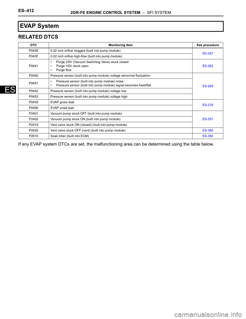
RELATED DTCS
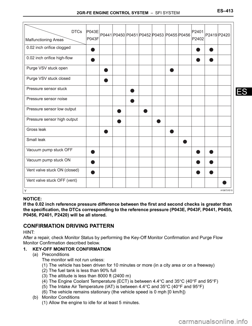
If any EVAP system DTCs are set, the malfunctioning area can be determined using the table below.
EVAP System
DTC Monitoring Item See procedure
P043E 0.02 inch orifice clogged (built into pump module)
ES-257
P043F 0.02 inch orifice high-flow (built into pump module)
P0441• Purge VSV (Vacuum Switching Valve) stuck closed
• Purge VSV stuck open
• Purge flowES-262
P0450 Pressure sensor (built into pump module) voltage abnormal fluctuation
ES-269 P0451• Pressure sensor (built into pump module) noise
• Pressure sensor (built into pump module) signal becomes fixed/flat
P0452 Pressure sensor (built into pump module) voltage low
P0453 Pressure sensor (built into pump module) voltage high
P0455 EVAP gross leak
ES-278
P0456 EVAP small leak
P2401 Vacuum pump stuck OFF (built into pump module)
ES-257 P2402 Vacuum pump stuck ON (built into pump module)
P2419 Vent valve stuck ON (closed) (built into pump module)
P2420 Vent valve stuck OFF (vent) (built into pump module)ES-380
P2610 Soak timer (built into ECM)ES-384
Page 699 of 3000
2GR-FE ENGINE CONTROL SYSTEM – SFI SYSTEMES–413
ES
NOTICE:
If the 0.02 inch reference pressure difference between the first and second checks is greater than
the specification, the DTCs corresponding to the reference pressure (P043E, P043F, P0441, P0455,
P0456, P2401, P2420) will be all stored.
CONFIRMATION DRIVING PATTERN
HINT:
After a repair, check Monitor Status by performing the Key-Off Monitor Confirmation and Purge Flow
Monitor Confirmation described below.
1. KEY-OFF MONITOR CONFIRMATION
(a) Preconditions
The monitor will not run unless:
(1) The vehicle has been driven for 10 minutes or more (in a city area or on a freeway)
(2) The fuel tank is less than 90% full
(3) The altitude is less than 8000 ft (2400 m)
(4) The Engine Coolant Temperature (ECT) is between 4.4
C and 35C (40F and 95F)
(5) The Intake Air Temperature (IAT) is between 4.4
C and 35C (40F and 95F)
(6) The vehicle remains stationary (the vehicle speed is 0 mph [0 km/h])
(b) Monitor Conditions
(1) Allow the engine to idle for at least 5 minutes.
A106731E15
Page 700 of 3000

ES–4142GR-FE ENGINE CONTROL SYSTEM – SFI SYSTEM
ES
(2) Turn the ignition switch off and wait for 6 hours (8 or 10.5 hours).
HINT:
Do not start the engine until checking MONITOR STATUS. If the engine is started, the steps
described above must be repeated.
(c) Monitor Status
(1) Connect the intelligent tester to the DLC3.
(2) Turn the ignition switch to the ON position and turn the tester on.
(3) Select the following menu items: DIAGNOSIS / ENHANCED OBD II / MONITOR STATUS.
(4) Check the "Monitor Status" displayed on the tester.
HINT:
If INCMP is displayed, the monitor is not completed. Make sure that the preconditions have
been met, and perform "Monitor Conditions" again.
2. PURGE FLOW MONITOR CONFIRMATION (P0441)
HINT:
Perform this monitor confirmation after the Key-Off Monitor Confirmation shows COMPL (complete).
(a) Preconditions
The monitor will not run unless:
• The vehicle has been driven for 10 minutes or more (in a city area or on a freeway)
• The ECT is between 4.4
C and 35C (40F and 95F)
• The IAT is between 4.4
C and 35C (40F and 95F)
(b) Monitor Conditions
(1) Release the pressure from the fuel tank by removing and reinstalling the fuel tank cap.
(2) Warm the engine up until the ECT reaches more than 75
C (167F).
(3) Increase the engine speed to 3000 rpm once.
(4) Allow the engine to idle and turn the A/C ON for 1 minute.
(c) Monitor Status
(1) Turn the ignition switch off.
(2) Connect the intelligent tester to the DLC3.
(3) Turn the ignition switch to the ON position and turn the tester on.
(4) Select the following menu items: DIAGNOSIS / ENHANCED OBD II / MONITOR STATUS.
(5) Check the "Monitor Status" displayed on the tester.
HINT:
If INCMP is displayed, the monitor is not completed. Make sure that the preconditions have
been met, and perform "Monitor Conditions" again.
MONITOR RESULT
Refer to Checking Monitor Status for detailed information (See page ES-19).
The test value and test limit information are described as shown in the following table. This information is
included in MONITOR RESULT of the emissions-related DTC sections:
– MID (Monitor Identification Data) is assigned to each emissions-related component.
– TID (Test Identification Data) is assigned to each test value.
– Scaling is used to calculate the test value indicated on generic OBD II scan tools.
Thermostat
MID TID Scaling Description of Test Value Minimum Test Limit Maximum Test Limit
$3D $C9 Multiply by 0.01 [kPa]Test value for small leak (P0456)
Refer to pressure D*Minimum test limit for
small leakMaximum test limit for
small leak
$3D $CA Multiply by 0.01 [kPa]Test value for gross leak (P0455)
Refer to pressure E*Minimum test limit for
gross leakMaximum test limit for
gross leak
$3D $CB Multiply by 0.01 [kPa]Test value for vacuum pump stuck OFF
(P2401)
Refer to pressure A*Minimum test limit for
vacuum pump stuck
OFFMaximum test limit for
vacuum pump stuck
OFF
$3D $CD Multiply by 0.01 [kPa]Test value for vacuum pump stuck ON
(P2402)
Refer to pressure A*Minimum test limit for
vacuum pump stuck
ONMaximum test limit for
vacuum pump stuck
ON