TOYOTA SIENNA 2007 Service Repair Manual
SIENNA 2007
TOYOTA
TOYOTA
https://www.carmanualsonline.info/img/14/57466/w960_57466-0.png
TOYOTA SIENNA 2007 Service Repair Manual
Trending: jump start, fuse box, maintenance reset, warning lights, belt, length, dimensions
Page 731 of 3000
2GR-FE ENGINE CONTROL SYSTEM – SFI SYSTEMES–445
ES
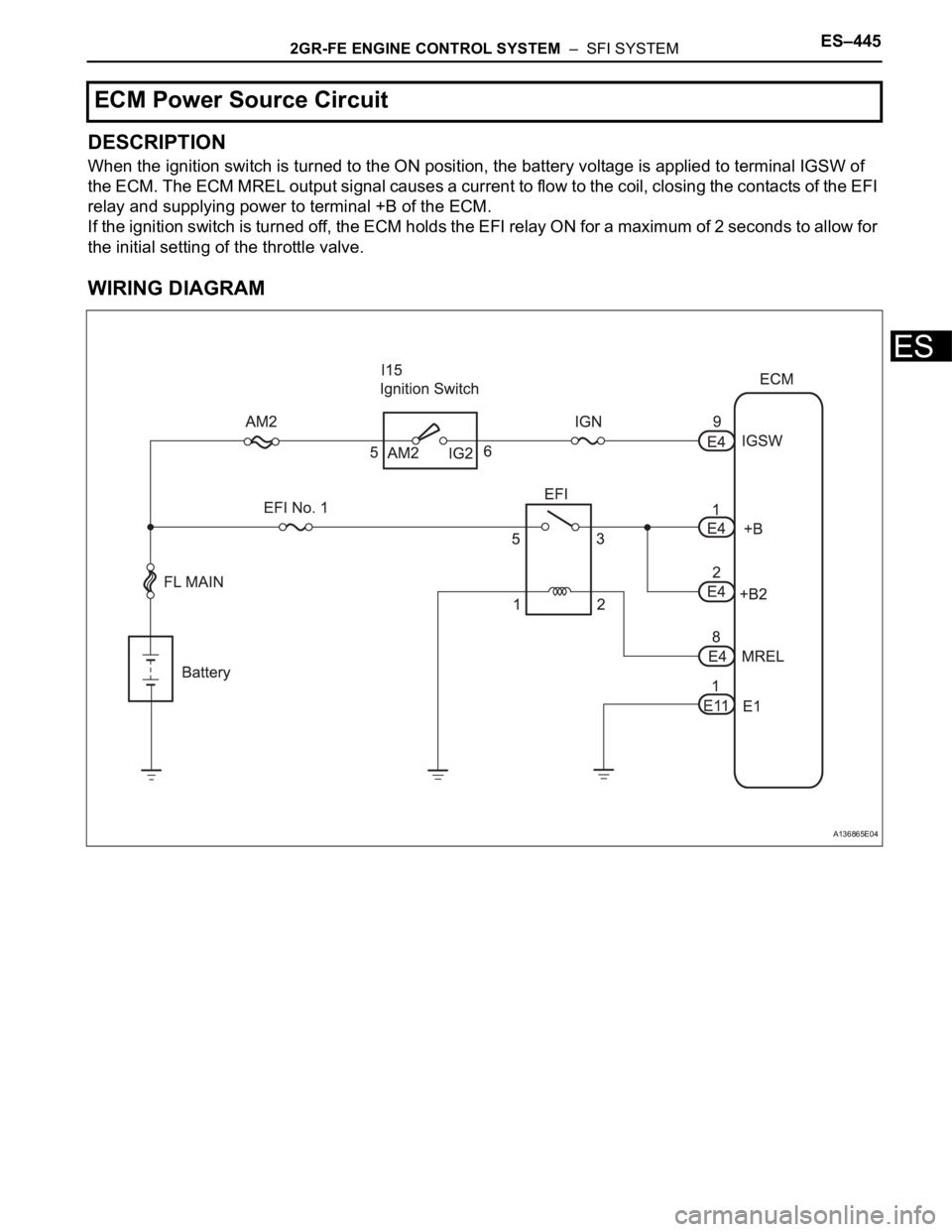
DESCRIPTION
When the ignition switch is turned to the ON position, the battery voltage is applied to terminal IGSW of
the ECM. The ECM MREL output signal causes a current to flow to the coil, closing the contacts of the EFI
relay and supplying power to terminal +B of the ECM.
If the ignition switch is turned off, the ECM holds the EFI relay ON for a maximum of 2 seconds to allow for
the initial setting of the throttle valve.
WIRING DIAGRAM
ECM Power Source Circuit
A136865E04
Page 732 of 3000
ES–4462GR-FE ENGINE CONTROL SYSTEM – SFI SYSTEM
ES
INSPECTION PROCEDURE
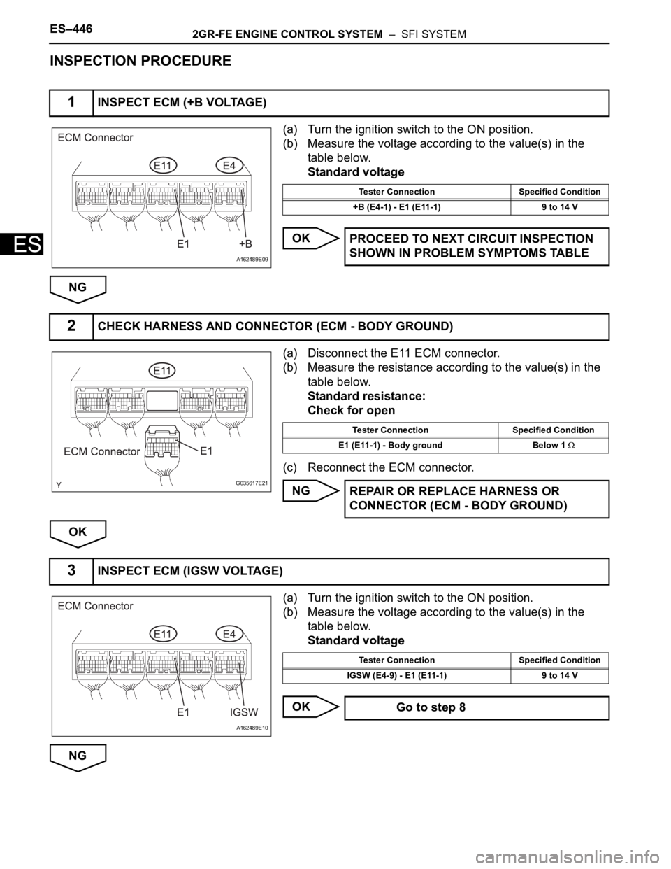
(a) Turn the ignition switch to the ON position.
(b) Measure the voltage according to the value(s) in the
table below.
Standard voltage
OK
NG
(a) Disconnect the E11 ECM connector.
(b) Measure the resistance according to the value(s) in the
table below.
Standard resistance:
Check for open
(c) Reconnect the ECM connector.
NG
OK
(a) Turn the ignition switch to the ON position.
(b) Measure the voltage according to the value(s) in the
table below.
Standard voltage
OK
NG
1INSPECT ECM (+B VOLTAGE)
A162489E09
Tester Connection Specified Condition
+B (E4-1) - E1 (E11-1) 9 to 14 V
PROCEED TO NEXT CIRCUIT INSPECTION
SHOWN IN PROBLEM SYMPTOMS TABLE
2CHECK HARNESS AND CONNECTOR (ECM - BODY GROUND)
G035617E21
Tester Connection Specified Condition
E1 (E11-1) - Body ground Below 1
REPAIR OR REPLACE HARNESS OR
CONNECTOR (ECM - BODY GROUND)
3INSPECT ECM (IGSW VOLTAGE)
A162489E10
Tester Connection Specified Condition
IGSW (E4-9) - E1 (E11-1) 9 to 14 V
Go to step 8
Page 733 of 3000
2GR-FE ENGINE CONTROL SYSTEM – SFI SYSTEMES–447
ES
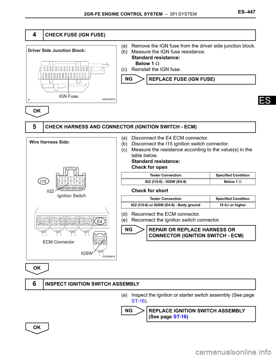
(a) Remove the IGN fuse from the driver side junction block.
(b) Measure the IGN fuse resistance.
Standard resistance:
Below 1
(c) Reinstall the IGN fuse.
NG
OK
(a) Disconnect the E4 ECM connector.
(b) Disconnect the I15 ignition switch connector.
(c) Measure the resistance according to the value(s) in the
table below.
Standard resistance:
Check for open
Check for short
(d) Reconnect the ECM connector.
(e) Reconnect the ignition switch connector.
NG
OK
(a) Inspect the ignition or starter switch assembly (See page
ST-16).
NG
OK
4CHECK FUSE (IGN FUSE)
A080034E03
REPLACE FUSE (IGN FUSE)
5CHECK HARNESS AND CONNECTOR (IGNITION SWITCH - ECM)
A162568E02
Tester Connection Specified Condition
IG2 (I15-6) - IGSW (E4-9) Below 1
Tester Connection Specified Condition
IG2 (I15-6) or IGSW (E4-9) - Body ground 10 k
or higher
REPAIR OR REPLACE HARNESS OR
CONNECTOR (IGNITION SWITCH - ECM)
6INSPECT IGNITION SWITCH ASSEMBLY
REPLACE IGNITION SWITCH ASSEMBLY
(See page ST-16)
Page 734 of 3000
ES–4482GR-FE ENGINE CONTROL SYSTEM – SFI SYSTEM
ES
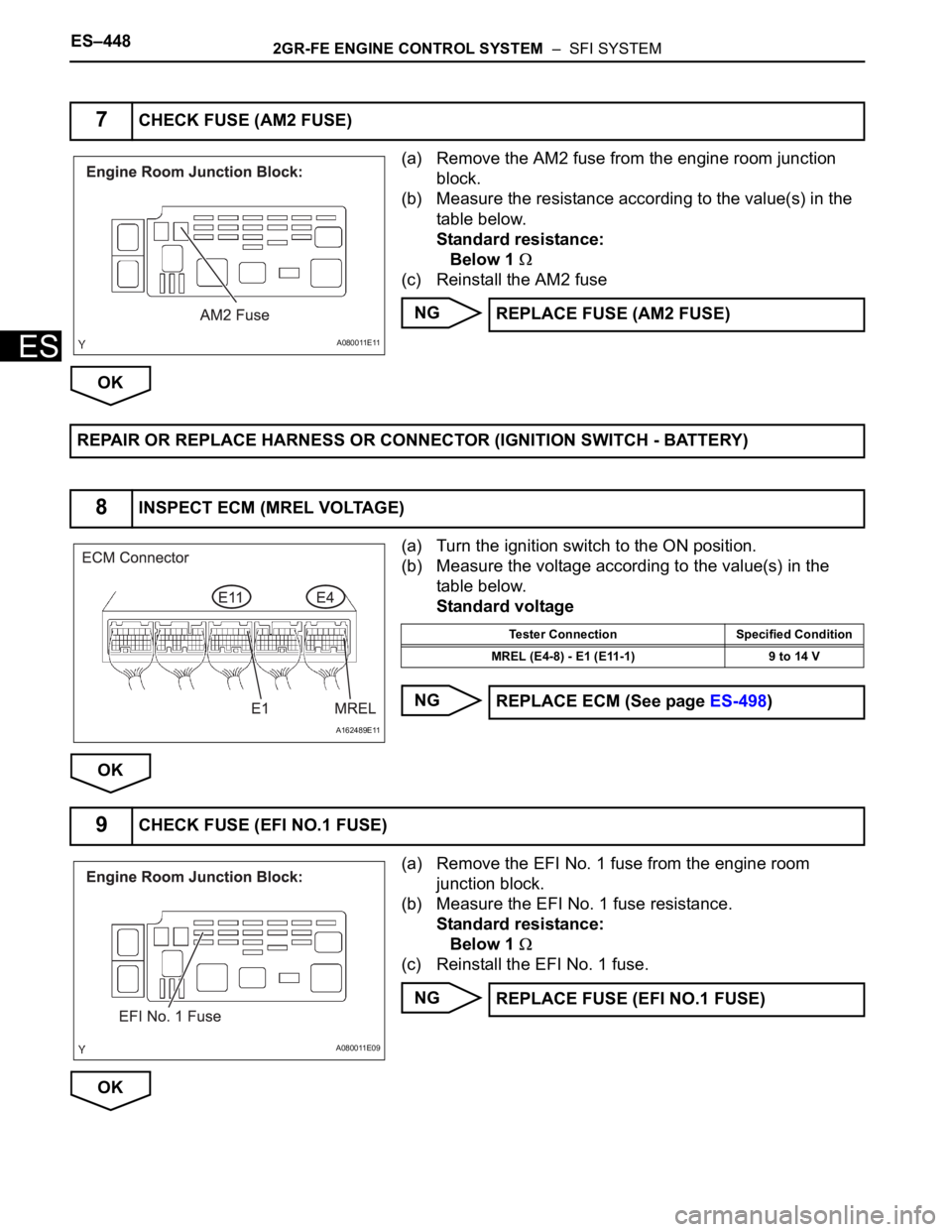
(a) Remove the AM2 fuse from the engine room junction
block.
(b) Measure the resistance according to the value(s) in the
table below.
Standard resistance:
Below 1
(c) Reinstall the AM2 fuse
NG
OK
(a) Turn the ignition switch to the ON position.
(b) Measure the voltage according to the value(s) in the
table below.
Standard voltage
NG
OK
(a) Remove the EFI No. 1 fuse from the engine room
junction block.
(b) Measure the EFI No. 1 fuse resistance.
Standard resistance:
Below 1
(c) Reinstall the EFI No. 1 fuse.
NG
OK
7CHECK FUSE (AM2 FUSE)
A080011E11
REPLACE FUSE (AM2 FUSE)
REPAIR OR REPLACE HARNESS OR CONNECTOR (IGNITION SWITCH - BATTERY)
8INSPECT ECM (MREL VOLTAGE)
A162489E11
Tester Connection Specified Condition
MREL (E4-8) - E1 (E11-1) 9 to 14 V
REPLACE ECM (See page ES-498)
9CHECK FUSE (EFI NO.1 FUSE)
A080011E09
REPLACE FUSE (EFI NO.1 FUSE)
Page 735 of 3000
2GR-FE ENGINE CONTROL SYSTEM – SFI SYSTEMES–449
ES
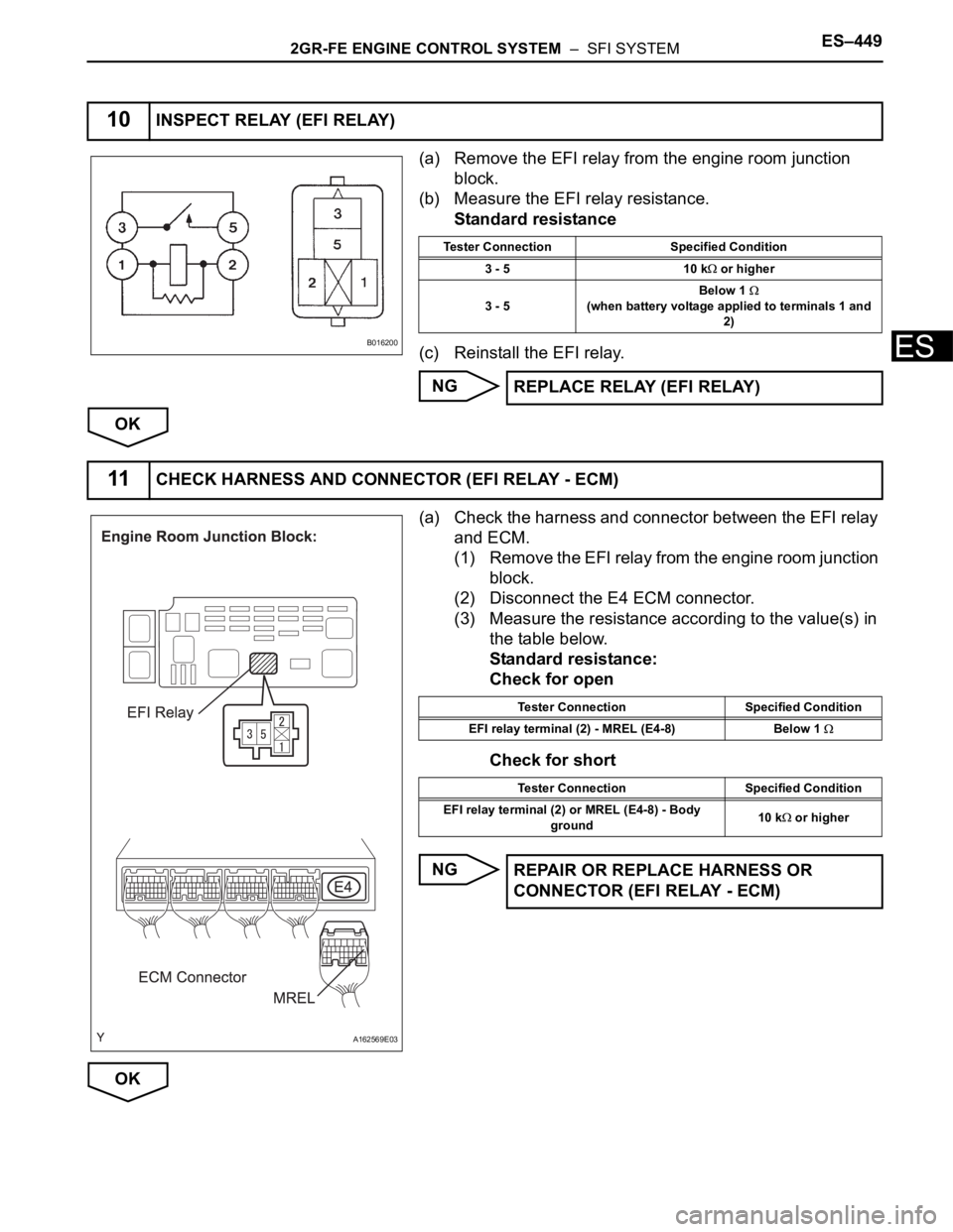
(a) Remove the EFI relay from the engine room junction
block.
(b) Measure the EFI relay resistance.
Standard resistance
(c) Reinstall the EFI relay.
NG
OK
(a) Check the harness and connector between the EFI relay
and ECM.
(1) Remove the EFI relay from the engine room junction
block.
(2) Disconnect the E4 ECM connector.
(3) Measure the resistance according to the value(s) in
the table below.
Standard resistance:
Check for open
Check for short
NG
OK
10INSPECT RELAY (EFI RELAY)
B016200
Tester Connection Specified Condition
3 - 5 10 k
or higher
3 - 5Below 1
(when battery voltage applied to terminals 1 and
2)
REPLACE RELAY (EFI RELAY)
11CHECK HARNESS AND CONNECTOR (EFI RELAY - ECM)
A162569E03
Tester Connection Specified Condition
EFI relay terminal (2) - MREL (E4-8) Below 1
Tester Connection Specified Condition
EFI relay terminal (2) or MREL (E4-8) - Body
ground10 k
or higher
REPAIR OR REPLACE HARNESS OR
CONNECTOR (EFI RELAY - ECM)
Page 736 of 3000
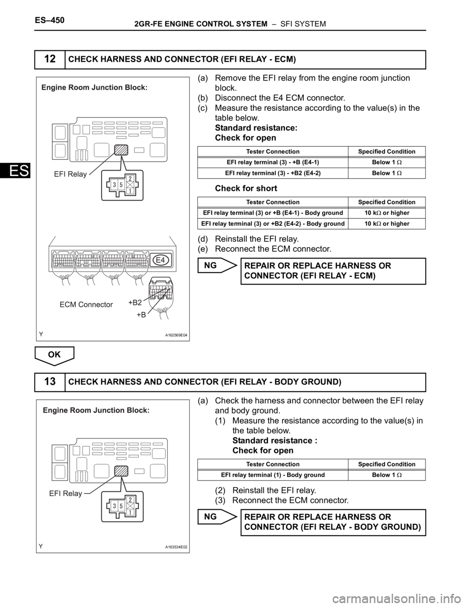
ES–4502GR-FE ENGINE CONTROL SYSTEM – SFI SYSTEM
ES
(a) Remove the EFI relay from the engine room junction
block.
(b) Disconnect the E4 ECM connector.
(c) Measure the resistance according to the value(s) in the
table below.
Standard resistance:
Check for open
Check for short
(d) Reinstall the EFI relay.
(e) Reconnect the ECM connector.
NG
OK
(a) Check the harness and connector between the EFI relay
and body ground.
(1) Measure the resistance according to the value(s) in
the table below.
Standard resistance :
Check for open
(2) Reinstall the EFI relay.
(3) Reconnect the ECM connector.
NG
12CHECK HARNESS AND CONNECTOR (EFI RELAY - ECM)
A162569E04
Tester Connection Specified Condition
EFI relay terminal (3) - +B (E4-1) Below 1
EFI relay terminal (3) - +B2 (E4-2) Below 1
Tester Connection Specified Condition
EFI relay terminal (3) or +B (E4-1) - Body ground 10 k
or higher
EFI relay terminal (3) or +B2 (E4-2) - Body ground 10 k
or higher
REPAIR OR REPLACE HARNESS OR
CONNECTOR (EFI RELAY - ECM)
13CHECK HARNESS AND CONNECTOR (EFI RELAY - BODY GROUND)
A163534E02
Tester Connection Specified Condition
EFI relay terminal (1) - Body ground Below 1
REPAIR OR REPLACE HARNESS OR
CONNECTOR (EFI RELAY - BODY GROUND)
Page 737 of 3000
2GR-FE ENGINE CONTROL SYSTEM – SFI SYSTEMES–451
ES
OK
REPAIR OR REPLACE HARNESS OR CONNECTOR (EFI RELAY - BATTERY)
Page 738 of 3000
ES–4522GR-FE ENGINE CONTROL SYSTEM – SFI SYSTEM
ES
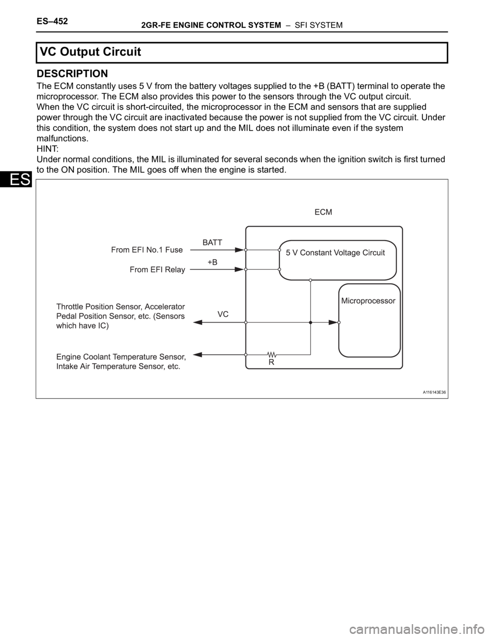
DESCRIPTION
The ECM constantly uses 5 V from the battery voltages supplied to the +B (BATT) terminal to operate the
microprocessor. The ECM also provides this power to the sensors through the VC output circuit.
When the VC circuit is short-circuited, the microprocessor in the ECM and sensors that are supplied
power through the VC circuit are inactivated because the power is not supplied from the VC circuit. Under
this condition, the system does not start up and the MIL does not illuminate even if the system
malfunctions.
HINT:
Under normal conditions, the MIL is illuminated for several seconds when the ignition switch is first turned
to the ON position. The MIL goes off when the engine is started.
VC Output Circuit
A116143E36
Page 739 of 3000
2GR-FE ENGINE CONTROL SYSTEM – SFI SYSTEMES–453
ES
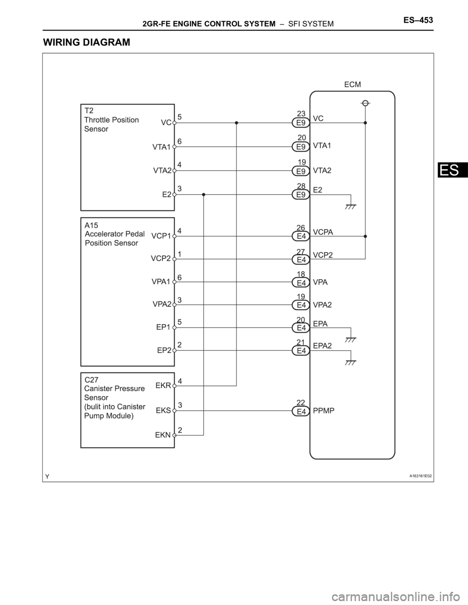
WIRING DIAGRAM
A163161E02
Page 740 of 3000
ES–4542GR-FE ENGINE CONTROL SYSTEM – SFI SYSTEM
ES
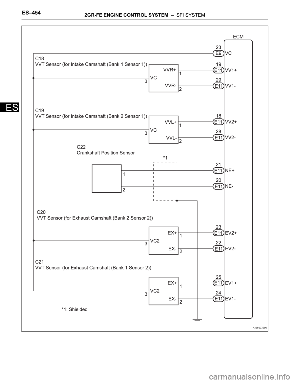
A136097E06
Trending: headlight aiming, cruise control, Dash, mirror, 4WD, throttle body, ad blue
