air bleeding TOYOTA SIENNA 2007 Service Repair Manual
[x] Cancel search | Manufacturer: TOYOTA, Model Year: 2007, Model line: SIENNA, Model: TOYOTA SIENNA 2007Pages: 3000, PDF Size: 52.26 MB
Page 906 of 3000
2GR-FE ENGINE MECHANICAL – ENGINE UNITEM–101
EM
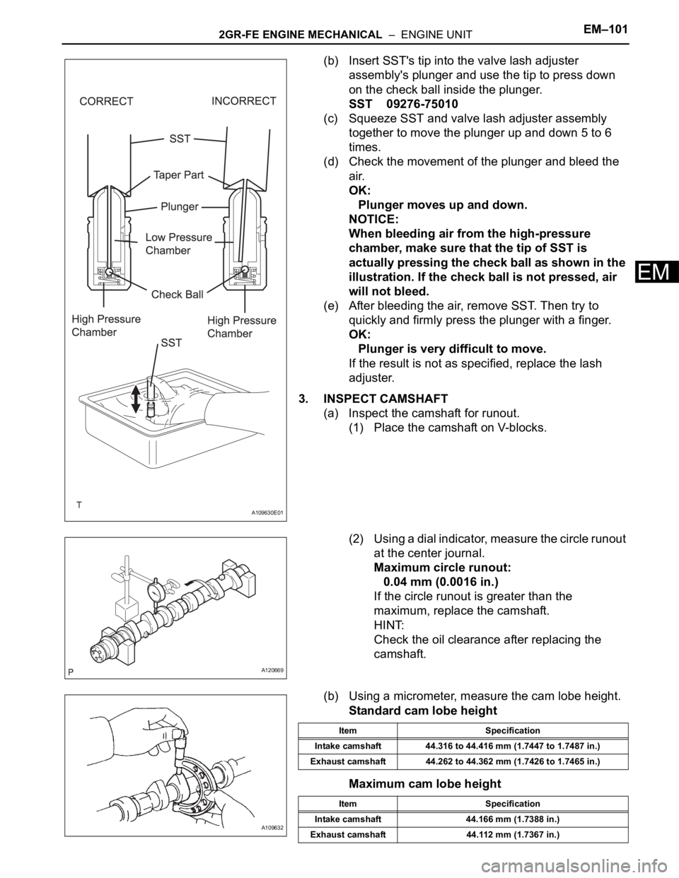
(b) Insert SST's tip into the valve lash adjuster
assembly's plunger and use the tip to press down
on the check ball inside the plunger.
SST 09276-75010
(c) Squeeze SST and valve lash adjuster assembly
together to move the plunger up and down 5 to 6
times.
(d) Check the movement of the plunger and bleed the
air.
OK:
Plunger moves up and down.
NOTICE:
When bleeding air from the high-pressure
chamber, make sure that the tip of SST is
actually pressing the check ball as shown in the
illustration. If the check ball is not pressed, air
will not bleed.
(e) After bleeding the air, remove SST. Then try to
quickly and firmly press the plunger with a finger.
OK:
Plunger is very difficult to move.
If the result is not as specified, replace the lash
adjuster.
3. INSPECT CAMSHAFT
(a) Inspect the camshaft for runout.
(1) Place the camshaft on V-blocks.
(2) Using a dial indicator, measure the circle runout
at the center journal.
Maximum circle runout:
0.04 mm (0.0016 in.)
If the circle runout is greater than the
maximum, replace the camshaft.
HINT:
Check the oil clearance after replacing the
camshaft.
(b) Using a micrometer, measure the cam lobe height.
Standard cam lobe height
Maximum cam lobe height
A109630E01
A120669
A109632
Item Specification
Intake camshaft 44.316 to 44.416 mm (1.7447 to 1.7487 in.)
Exhaust camshaft 44.262 to 44.362 mm (1.7426 to 1.7465 in.)
Item Specification
Intake camshaft 44.166 mm (1.7388 in.)
Exhaust camshaft 44.112 mm (1.7367 in.)
Page 953 of 3000
EM–1442GR-FE ENGINE MECHANICAL – ENGINE UNIT
EM
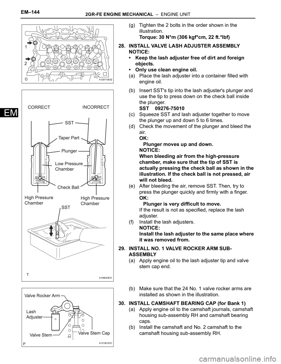
(g) Tighten the 2 bolts in the order shown in the
illustration.
Torque: 30 N*m (306 kgf*cm, 22 ft.*lbf)
28. INSTALL VALVE LASH ADJUSTER ASSEMBLY
NOTICE:
• Keep the lash adjuster free of dirt and foreign
objects.
• Only use clean engine oil.
(a) Place the lash adjuster into a container filled with
engine oil.
(b) Insert SST's tip into the lash adjuster's plunger and
use the tip to press down on the check ball inside
the plunger.
SST 09276-75010
(c) Squeeze SST and lash adjuster together to move
the plunger up and down 5 to 6 times.
(d) Check the movement of the plunger and bleed the
air.
OK:
Plunger moves up and down.
NOTICE:
When bleeding air from the high-pressure
chamber, make sure that the tip of SST is
actually pressing the check ball as shown in the
illustration. If the check ball is not pressed, air
will not bleed.
(e) After bleeding the air, remove SST. Then, try to
press the plunger quickly and firmly with a finger.
OK:
Plunger is very difficult to move.
If the result is not as specified, replace the lash
adjuster.
(f) Install the lash adjusters.
NOTICE:
Install the lash adjuster to the same place where
it was removed from.
29. INSTALL NO. 1 VALVE ROCKER ARM SUB-
ASSEMBLY
(a) Apply engine oil to the lash adjuster tip and valve
stem cap end.
(b) Make sure that the 24 No. 1 valve rocker arms are
installed as shown in the illustration.
30. INSTALL CAMSHAFT BEARING CAP (for Bank 1)
(a) Apply engine oil to the camshaft journals, camshaft
housing sub-assembly RH and camshaft bearing
caps.
(b) Install the camshaft and No. 2 camshaft to the
camshaft housing sub-assembly RH.
A129710E02
A109630E01
A131901E01
Page 1048 of 3000
2GR-FE ENGINE MECHANICAL – ENGINE UNITEM–101
EM
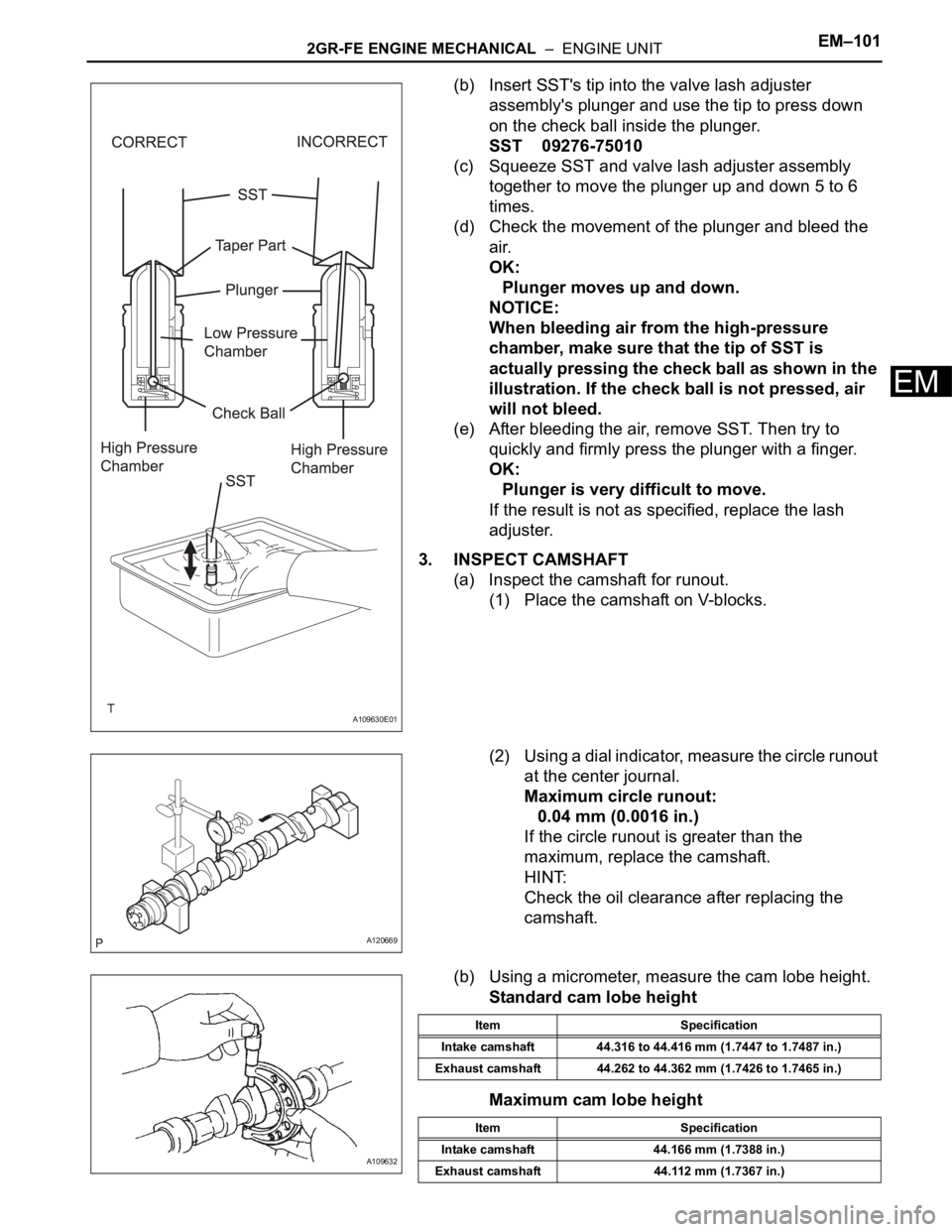
(b) Insert SST's tip into the valve lash adjuster
assembly's plunger and use the tip to press down
on the check ball inside the plunger.
SST 09276-75010
(c) Squeeze SST and valve lash adjuster assembly
together to move the plunger up and down 5 to 6
times.
(d) Check the movement of the plunger and bleed the
air.
OK:
Plunger moves up and down.
NOTICE:
When bleeding air from the high-pressure
chamber, make sure that the tip of SST is
actually pressing the check ball as shown in the
illustration. If the check ball is not pressed, air
will not bleed.
(e) After bleeding the air, remove SST. Then try to
quickly and firmly press the plunger with a finger.
OK:
Plunger is very difficult to move.
If the result is not as specified, replace the lash
adjuster.
3. INSPECT CAMSHAFT
(a) Inspect the camshaft for runout.
(1) Place the camshaft on V-blocks.
(2) Using a dial indicator, measure the circle runout
at the center journal.
Maximum circle runout:
0.04 mm (0.0016 in.)
If the circle runout is greater than the
maximum, replace the camshaft.
HINT:
Check the oil clearance after replacing the
camshaft.
(b) Using a micrometer, measure the cam lobe height.
Standard cam lobe height
Maximum cam lobe height
A109630E01
A120669
A109632
Item Specification
Intake camshaft 44.316 to 44.416 mm (1.7447 to 1.7487 in.)
Exhaust camshaft 44.262 to 44.362 mm (1.7426 to 1.7465 in.)
Item Specification
Intake camshaft 44.166 mm (1.7388 in.)
Exhaust camshaft 44.112 mm (1.7367 in.)
Page 1091 of 3000
EM–1442GR-FE ENGINE MECHANICAL – ENGINE UNIT
EM
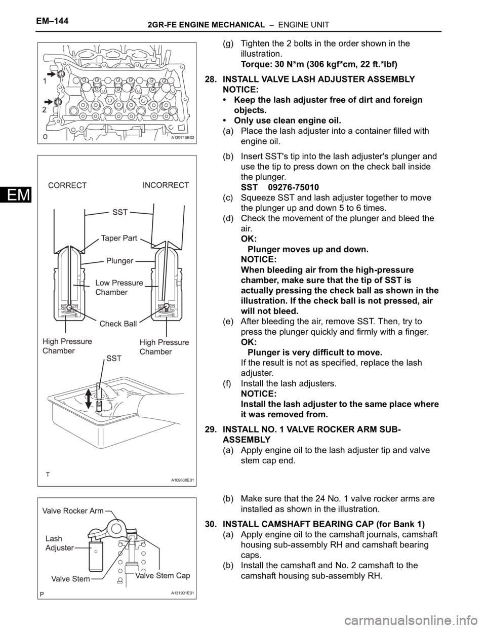
(g) Tighten the 2 bolts in the order shown in the
illustration.
Torque: 30 N*m (306 kgf*cm, 22 ft.*lbf)
28. INSTALL VALVE LASH ADJUSTER ASSEMBLY
NOTICE:
• Keep the lash adjuster free of dirt and foreign
objects.
• Only use clean engine oil.
(a) Place the lash adjuster into a container filled with
engine oil.
(b) Insert SST's tip into the lash adjuster's plunger and
use the tip to press down on the check ball inside
the plunger.
SST 09276-75010
(c) Squeeze SST and lash adjuster together to move
the plunger up and down 5 to 6 times.
(d) Check the movement of the plunger and bleed the
air.
OK:
Plunger moves up and down.
NOTICE:
When bleeding air from the high-pressure
chamber, make sure that the tip of SST is
actually pressing the check ball as shown in the
illustration. If the check ball is not pressed, air
will not bleed.
(e) After bleeding the air, remove SST. Then, try to
press the plunger quickly and firmly with a finger.
OK:
Plunger is very difficult to move.
If the result is not as specified, replace the lash
adjuster.
(f) Install the lash adjusters.
NOTICE:
Install the lash adjuster to the same place where
it was removed from.
29. INSTALL NO. 1 VALVE ROCKER ARM SUB-
ASSEMBLY
(a) Apply engine oil to the lash adjuster tip and valve
stem cap end.
(b) Make sure that the 24 No. 1 valve rocker arms are
installed as shown in the illustration.
30. INSTALL CAMSHAFT BEARING CAP (for Bank 1)
(a) Apply engine oil to the camshaft journals, camshaft
housing sub-assembly RH and camshaft bearing
caps.
(b) Install the camshaft and No. 2 camshaft to the
camshaft housing sub-assembly RH.
A129710E02
A109630E01
A131901E01
Page 2595 of 3000
BRAKE – BRAKE FLUIDBR–3
BR
BRAKE FLUID
BLEEDING
HINT:
If any work is performed on the brake system or if air in the
brake lines is suspected, bleed the air out of the brake
system.
NOTICE:
Wash the brake fluid off immediately if it adheres to any
painted surfaces.
1. REMOVE COWL TOP PANEL SUB-ASSEMBLY
OUTER FRONT (See page SP-13)
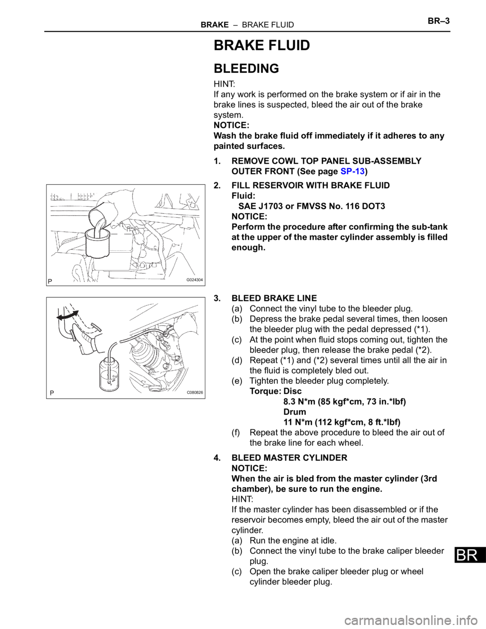
2. FILL RESERVOIR WITH BRAKE FLUID
Fluid:
SAE J1703 or FMVSS No. 116 DOT3
NOTICE:
Perform the procedure after confirming the sub-tank
at the upper of the master cylinder assembly is filled
enough.
3. BLEED BRAKE LINE
(a) Connect the vinyl tube to the bleeder plug.
(b) Depress the brake pedal several times, then loosen
the bleeder plug with the pedal depressed (*1).
(c) At the point when fluid stops coming out, tighten the
bleeder plug, then release the brake pedal (*2).
(d) Repeat (*1) and (*2) several times until all the air in
the fluid is completely bled out.
(e) Tighten the bleeder plug completely.
Torque: Disc
8.3 N*m (85 kgf*cm, 73 in.*lbf)
Drum
11 N*m (112 kgf*cm, 8 ft.*lbf)
(f) Repeat the above procedure to bleed the air out of
the brake line for each wheel.
4. BLEED MASTER CYLINDER
NOTICE:
When the air is bled from the master cylinder (3rd
chamber), be sure to run the engine.
HINT:
If the master cylinder has been disassembled or if the
reservoir becomes empty, bleed the air out of the master
cylinder.
(a) Run the engine at idle.
(b) Connect the vinyl tube to the brake caliper bleeder
plug.
(c) Open the brake caliper bleeder plug or wheel
cylinder bleeder plug.
G024304
C080826
Page 2596 of 3000
BR–4BRAKE – BRAKE FLUID
BR
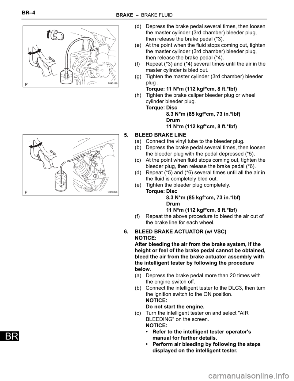
(d) Depress the brake pedal several times, then loosen
the master cylinder (3rd chamber) bleeder plug,
then release the brake pedal (*3).
(e) At the point when the fluid stops coming out, tighten
the master cylinder (3rd chamber) bleeder plug,
then release the brake pedal (*4).
(f) Repeat (*3) and (*4) several times until the air in the
master cylinder is bled out.
(g) Tighten the master cylinder (3rd chamber) bleeder
plug .
Torque: 11 N*m (112 kgf*cm, 8 ft.*lbf)
(h) Tighten the brake caliper bleeder plug or wheel
cylinder bleeder plug.
Torque: Disc
8.3 N*m (85 kgf*cm, 73 in.*lbf)
Drum
11 N*m (112 kgf*cm, 8 ft.*lbf)
5. BLEED BRAKE LINE
(a) Connect the vinyl tube to the bleeder plug.
(b) Depress the brake pedal several times, then loosen
the bleeder plug with the pedal depressed (*5).
(c) At the point when fluid stops coming out, tighten the
bleeder plug, then release the brake pedal (*6).
(d) Repeat (*5) and (*6) several times until all the air in
the fluid is completely bled out.
(e) Tighten the bleeder plug completely.
Torque: Disc
8.3 N*m (85 kgf*cm, 73 in.*lbf)
Drum
11 N*m (112 kgf*cm, 8 ft.*lbf)
(f) Repeat the above procedure to bleed the air out of
the brake line for each wheel.
6. BLEED BRAKE ACTUATOR (w/ VSC)
NOTICE:
After bleeding the air from the brake system, if the
height or feel of the brake pedal cannot be obtained,
bleed the air from the brake actuator assembly with
the intelligent tester by following the procedure
below.
(a) Depress the brake pedal more than 20 times with
the engine switch off.
(b) Connect the intelligent tester to the DLC3, then turn
the ignition switch to the ON position.
NOTICE:
Do not start the engine.
(c) Turn the intelligent tester on and select "AIR
BLEEDING" on the screen.
NOTICE:
• Refer to the intelligent tester operator's
manual for farther details.
• Perform air bleeding by following the steps
displayed on the intelligent tester.
F045198
C080826
Page 2597 of 3000

BRAKE – BRAKE FLUIDBR–5
BR
(d) Perform air bleeding according to "Step 1: Increase"
on the intelligent tester display.
NOTICE:
Make sure that the master cylinder reservoir
tank does not become empty of brake fluid.
(1) Connect a vinyl tube to either one of the
bleeder plugs.
(2) Depress the brake pedal several times, then
loosen the bleeder plug connected to the vinyl
tube with the pedal depressed (*7).
(3) When fluid stops coming out, tighten the
bleeder plug, then release the brake pedal (*8).
(4) Repeat (*7) and (*8) until all the air in the fluid
is completely bled out.
(5) Tighten the bleeder plug completely.
To r q u e : D i s c
8.3 N*m (85 kgf*cm, 73 in.*lbf)
Drum
11 N*m (112 kgf*cm, 8 ft.*lbf)
(6) Repeat the above procedures for the rest of the
wheels to bleed the air from the brake line.
(e) Bleed the air from the suction line according to "Step
2: Inhalation" on the intelligent tester display.
NOTICE:
• Bleed the suction line by following the steps
displayed on the intelligent tester.
• Make sure that the master cylinder reservoir
tank does not become empty of brake fluid.
(1) Connect a vinyl tube to the bleeder plug at the
right front wheel or the right rear wheel and
loosen the bleeder plug.
(2) Operate the brake actuator assembly to
perform air bleeding using the intelligent tester
(*9).
NOTICE:
• The operation stops automatically in 4
seconds.
• At this time, be sure to release the brake
pedal.
(3) Check that the operation has stopped by
referring to the intelligent tester display and
tighten the bleeder plug (*10).
(4) Repeat (*9) and (*10) until all the air in the fluid
is completely bled out.
(5) Tighten the bleeder plug completely.
To r q u e : D i s c
8.3 N*m (85 kgf*cm, 73 in.*lbf)
Drum
11 N*m (112 kgf*cm, 8 ft.*lbf)
(6) For the rest of the wheels, perform air bleeding
in the same way as stated in the above
procedure.
Page 2599 of 3000

BRAKE – BRAKE FLUIDBR–7
BR
(3) When fluid stops coming out, tighten the
bleeder plug, then release the brake pedal
(*14).
(4) Repeat (*13) and (*14) until all the air in the
fluid is completely bled out.
(5) Tighten the bleeder plug completely.
To r q u e : D i s c
8.3 N*m (85 kgf*cm, 73 in.*lbf)
Drum
11 N*m (112 kgf*cm, 8 ft.*lbf)
(6) Repeat the above procedures for each brake to
bleed the air from the brake line.
(h) Finish "AIR BLEEDING" on the intelligent tester and
turn off the tester.
(i) Disconnect the intelligent tester from the DLC3.
(j) Turn the ignition switch to the OFF position.
7. CHECK FLUID LEVEL IN RESERVOIR
(a) Check the fluid level and add fluid, if necessary.
Fluid:
SAE J1703 or FMVSS No. 116 DOT3
8. INSTALL COWL TOP PANEL SUB-ASSEMBLY
OUTER FRONT