brake drum remove TOYOTA SIENNA 2007 Service Repair Manual
[x] Cancel search | Manufacturer: TOYOTA, Model Year: 2007, Model line: SIENNA, Model: TOYOTA SIENNA 2007Pages: 3000, PDF Size: 52.26 MB
Page 1559 of 3000
AX–180U151E AUTOMATIC TRANSAXLE – AUTOMATIC TRANSAXLE UNIT
AX
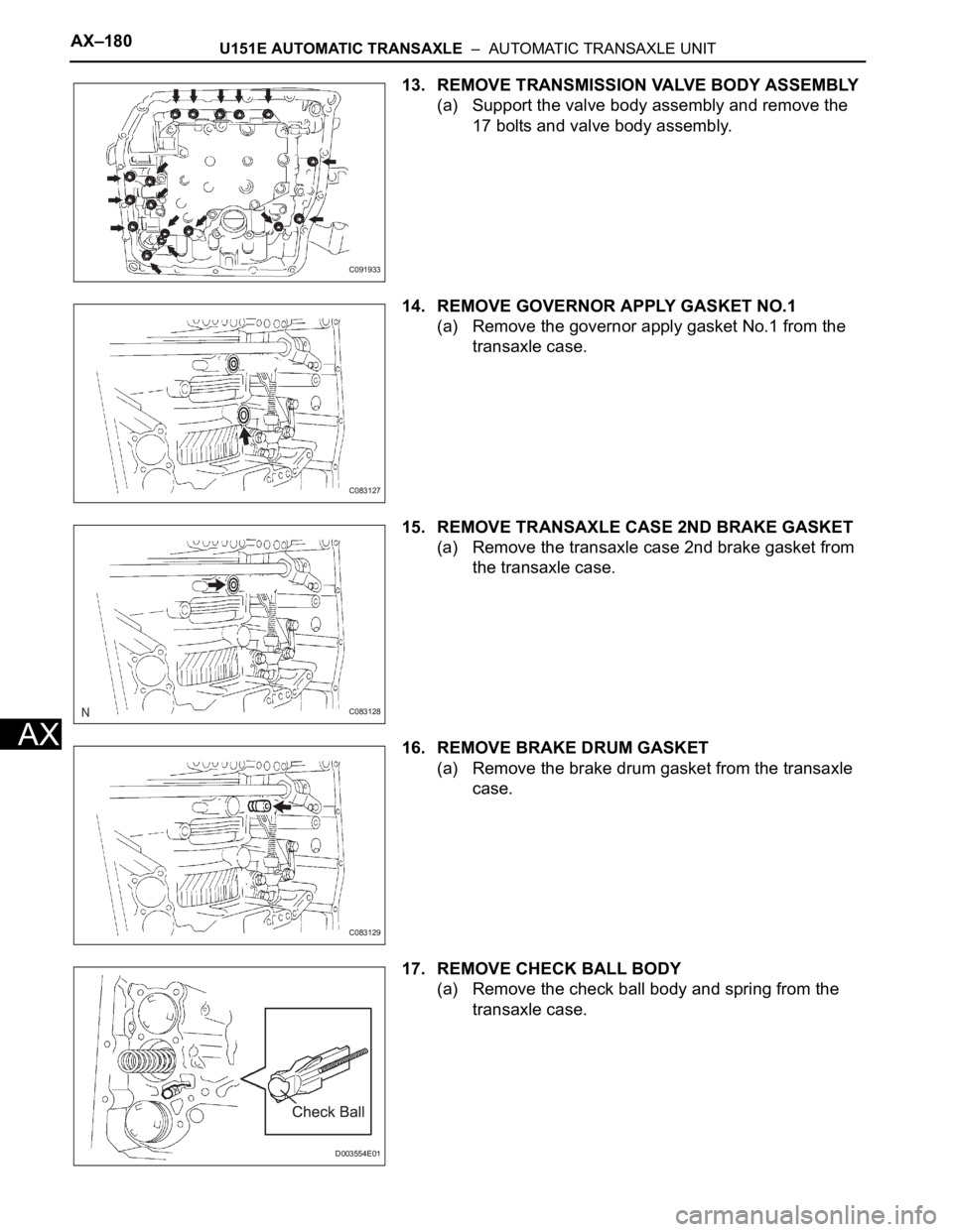
13. REMOVE TRANSMISSION VALVE BODY ASSEMBLY
(a) Support the valve body assembly and remove the
17 bolts and valve body assembly.
14. REMOVE GOVERNOR APPLY GASKET NO.1
(a) Remove the governor apply gasket No.1 from the
transaxle case.
15. REMOVE TRANSAXLE CASE 2ND BRAKE GASKET
(a) Remove the transaxle case 2nd brake gasket from
the transaxle case.
16. REMOVE BRAKE DRUM GASKET
(a) Remove the brake drum gasket from the transaxle
case.
17. REMOVE CHECK BALL BODY
(a) Remove the check ball body and spring from the
transaxle case.
C091933
C083127
C083128
C083129
D003554E01
Page 1568 of 3000
U151E AUTOMATIC TRANSAXLE – AUTOMATIC TRANSAXLE UNITAX–189
AX
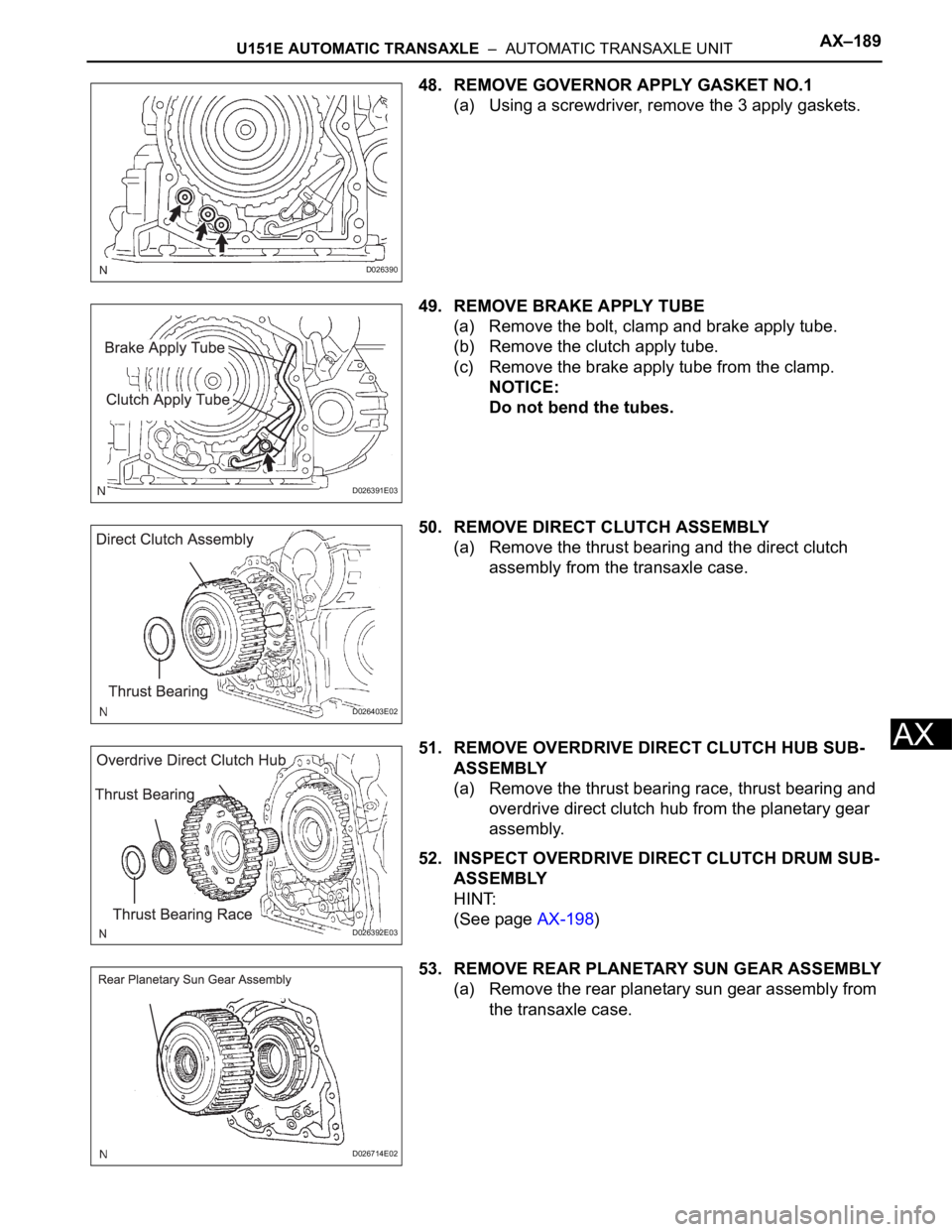
48. REMOVE GOVERNOR APPLY GASKET NO.1
(a) Using a screwdriver, remove the 3 apply gaskets.
49. REMOVE BRAKE APPLY TUBE
(a) Remove the bolt, clamp and brake apply tube.
(b) Remove the clutch apply tube.
(c) Remove the brake apply tube from the clamp.
NOTICE:
Do not bend the tubes.
50. REMOVE DIRECT CLUTCH ASSEMBLY
(a) Remove the thrust bearing and the direct clutch
assembly from the transaxle case.
51. REMOVE OVERDRIVE DIRECT CLUTCH HUB SUB-
ASSEMBLY
(a) Remove the thrust bearing race, thrust bearing and
overdrive direct clutch hub from the planetary gear
assembly.
52. INSPECT OVERDRIVE DIRECT CLUTCH DRUM SUB-
ASSEMBLY
HINT:
(See page AX-198)
53. REMOVE REAR PLANETARY SUN GEAR ASSEMBLY
(a) Remove the rear planetary sun gear assembly from
the transaxle case.
D026390
D026391E03
D026403E02
D026392E03
D026714E02
Page 1575 of 3000
AX–196U151E AUTOMATIC TRANSAXLE – AUTOMATIC TRANSAXLE UNIT
AX
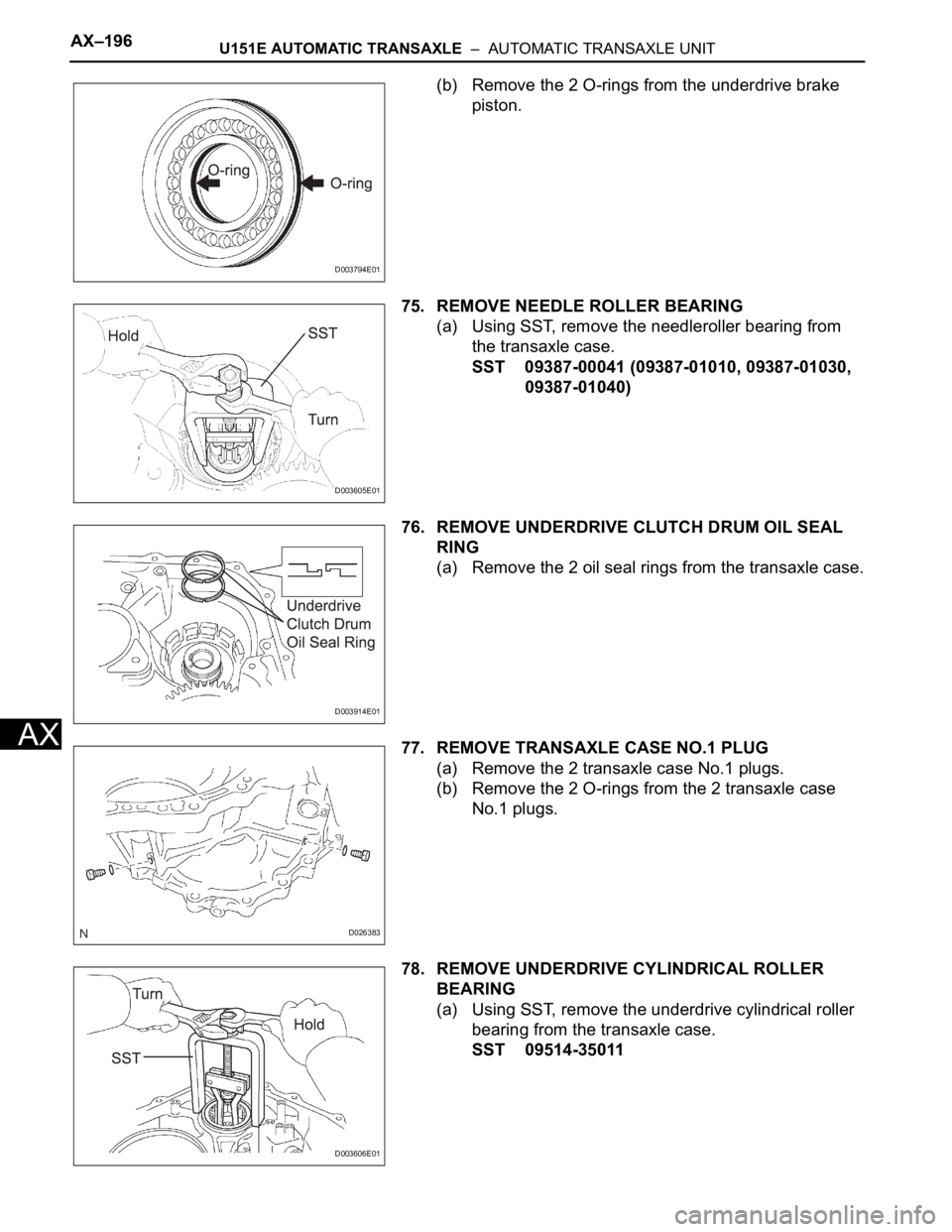
(b) Remove the 2 O-rings from the underdrive brake
piston.
75. REMOVE NEEDLE ROLLER BEARING
(a) Using SST, remove the needleroller bearing from
the transaxle case.
SST 09387-00041 (09387-01010, 09387-01030,
09387-01040)
76. REMOVE UNDERDRIVE CLUTCH DRUM OIL SEAL
RING
(a) Remove the 2 oil seal rings from the transaxle case.
77. REMOVE TRANSAXLE CASE NO.1 PLUG
(a) Remove the 2 transaxle case No.1 plugs.
(b) Remove the 2 O-rings from the 2 transaxle case
No.1 plugs.
78. REMOVE UNDERDRIVE CYLINDRICAL ROLLER
BEARING
(a) Using SST, remove the underdrive cylindrical roller
bearing from the transaxle case.
SST 09514-35011
D003794E01
D003605E01
D003914E01
D026383
D003606E01
Page 1589 of 3000
U151E AUTOMATIC TRANSAXLE – AUTOMATIC TRANSAXLE UNITAX–203
AX
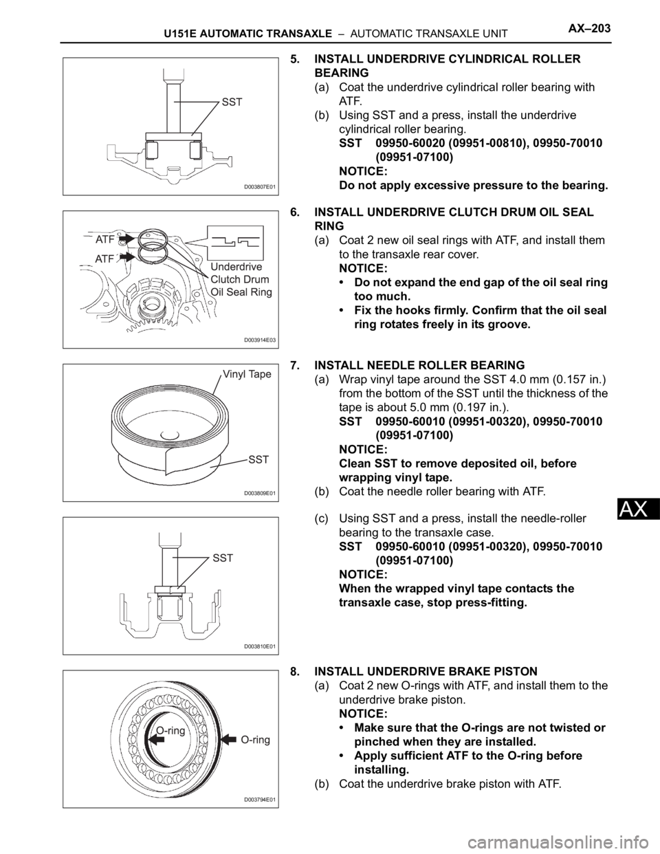
5. INSTALL UNDERDRIVE CYLINDRICAL ROLLER
BEARING
(a) Coat the underdrive cylindrical roller bearing with
AT F.
(b) Using SST and a press, install the underdrive
cylindrical roller bearing.
SST 09950-60020 (09951-00810), 09950-70010
(09951-07100)
NOTICE:
Do not apply excessive pressure to the bearing.
6. INSTALL UNDERDRIVE CLUTCH DRUM OIL SEAL
RING
(a) Coat 2 new oil seal rings with ATF, and install them
to the transaxle rear cover.
NOTICE:
• Do not expand the end gap of the oil seal ring
too much.
• Fix the hooks firmly. Confirm that the oil seal
ring rotates freely in its groove.
7. INSTALL NEEDLE ROLLER BEARING
(a) Wrap vinyl tape around the SST 4.0 mm (0.157 in.)
from the bottom of the SST until the thickness of the
tape is about 5.0 mm (0.197 in.).
SST 09950-60010 (09951-00320), 09950-70010
(09951-07100)
NOTICE:
Clean SST to remove deposited oil, before
wrapping vinyl tape.
(b) Coat the needle roller bearing with ATF.
(c) Using SST and a press, install the needle-roller
bearing to the transaxle case.
SST 09950-60010 (09951-00320), 09950-70010
(09951-07100)
NOTICE:
When the wrapped vinyl tape contacts the
transaxle case, stop press-fitting.
8. INSTALL UNDERDRIVE BRAKE PISTON
(a) Coat 2 new O-rings with ATF, and install them to the
underdrive brake piston.
NOTICE:
• Make sure that the O-rings are not twisted or
pinched when they are installed.
• Apply sufficient ATF to the O-ring before
installing.
(b) Coat the underdrive brake piston with ATF.
D003807E01
D003914E03
D003809E01
D003810E01
D003794E01
Page 1602 of 3000
AX–216U151E AUTOMATIC TRANSAXLE – AUTOMATIC TRANSAXLE UNIT
AX
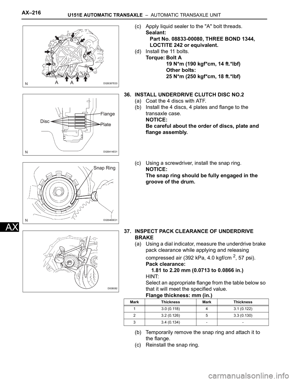
(c) Apply liquid sealer to the "A" bolt threads.
Sealant:
Part No. 08833-00080, THREE BOND 1344,
LOCTITE 242 or equivalent.
(d) Install the 11 bolts.
Torque: Bolt A
19 N*m (190 kgf*cm, 14 ft.*lbf)
Other bolts:
25 N*m (250 kgf*cm, 18 ft.*lbf)
36. INSTALL UNDERDRIVE CLUTCH DISC NO.2
(a) Coat the 4 discs with ATF.
(b) Install the 4 discs, 4 plates and flange to the
transaxle case.
NOTICE:
Be careful about the order of discs, plate and
flange assembly.
(c) Using a screwdriver, install the snap ring.
NOTICE:
The snap ring should be fully engaged in the
groove of the drum.
37. INSPECT PACK CLEARANCE OF UNDERDRIVE
BRAKE
(a) Using a dial indicator, measure the underdrive brake
pack clearance while applying and releasing
compressed air (392 kPa, 4.0 kgf/cm
2, 57 psi).
Pack clearance:
1.81 to 2.20 mm (0.0713 to 0.0866 in.)
HINT:
Select an appropriate flange from the table below so
that it will meet the specified value.
Flange thickness: mm (in.)
(b) Temporarily remove the snap ring and attach it to
the flange.
(c) Reinstall the snap ring.
D026387E03
D026414E01
D026466E01
D008082
Mark Thickness Mark Thickness
1 3.0 (0.118) 4 3.1 (0.122)
2 3.2 (0.126) 5 3.3 (0.130)
3 3.4 (0.134) - -
Page 1624 of 3000
AX–180U151E AUTOMATIC TRANSAXLE – AUTOMATIC TRANSAXLE UNIT
AX
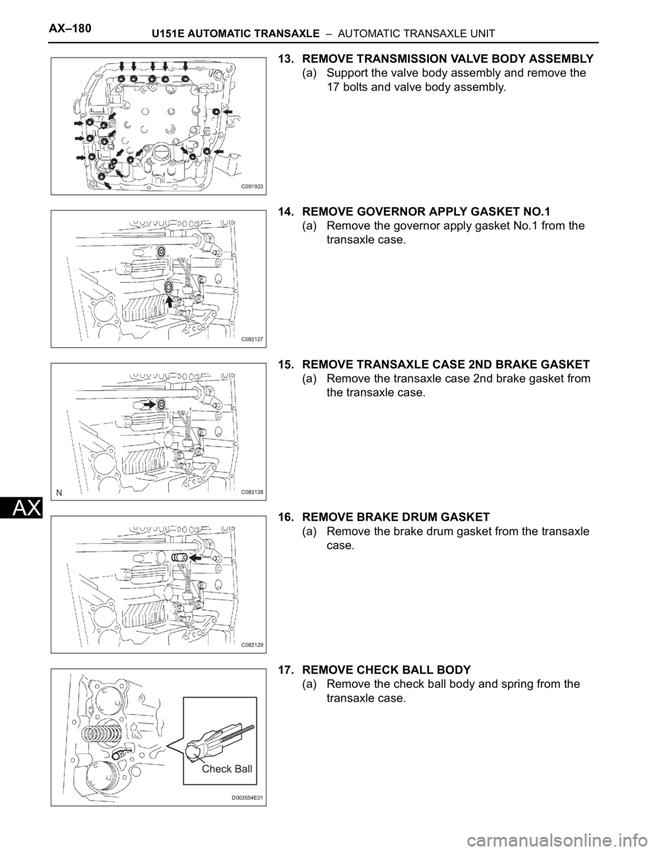
13. REMOVE TRANSMISSION VALVE BODY ASSEMBLY
(a) Support the valve body assembly and remove the
17 bolts and valve body assembly.
14. REMOVE GOVERNOR APPLY GASKET NO.1
(a) Remove the governor apply gasket No.1 from the
transaxle case.
15. REMOVE TRANSAXLE CASE 2ND BRAKE GASKET
(a) Remove the transaxle case 2nd brake gasket from
the transaxle case.
16. REMOVE BRAKE DRUM GASKET
(a) Remove the brake drum gasket from the transaxle
case.
17. REMOVE CHECK BALL BODY
(a) Remove the check ball body and spring from the
transaxle case.
C091933
C083127
C083128
C083129
D003554E01
Page 1633 of 3000
U151E AUTOMATIC TRANSAXLE – AUTOMATIC TRANSAXLE UNITAX–189
AX
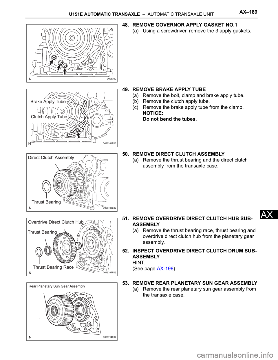
48. REMOVE GOVERNOR APPLY GASKET NO.1
(a) Using a screwdriver, remove the 3 apply gaskets.
49. REMOVE BRAKE APPLY TUBE
(a) Remove the bolt, clamp and brake apply tube.
(b) Remove the clutch apply tube.
(c) Remove the brake apply tube from the clamp.
NOTICE:
Do not bend the tubes.
50. REMOVE DIRECT CLUTCH ASSEMBLY
(a) Remove the thrust bearing and the direct clutch
assembly from the transaxle case.
51. REMOVE OVERDRIVE DIRECT CLUTCH HUB SUB-
ASSEMBLY
(a) Remove the thrust bearing race, thrust bearing and
overdrive direct clutch hub from the planetary gear
assembly.
52. INSPECT OVERDRIVE DIRECT CLUTCH DRUM SUB-
ASSEMBLY
HINT:
(See page AX-198)
53. REMOVE REAR PLANETARY SUN GEAR ASSEMBLY
(a) Remove the rear planetary sun gear assembly from
the transaxle case.
D026390
D026391E03
D026403E02
D026392E03
D026714E02
Page 1640 of 3000
AX–196U151E AUTOMATIC TRANSAXLE – AUTOMATIC TRANSAXLE UNIT
AX
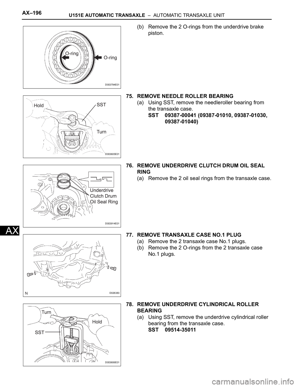
(b) Remove the 2 O-rings from the underdrive brake
piston.
75. REMOVE NEEDLE ROLLER BEARING
(a) Using SST, remove the needleroller bearing from
the transaxle case.
SST 09387-00041 (09387-01010, 09387-01030,
09387-01040)
76. REMOVE UNDERDRIVE CLUTCH DRUM OIL SEAL
RING
(a) Remove the 2 oil seal rings from the transaxle case.
77. REMOVE TRANSAXLE CASE NO.1 PLUG
(a) Remove the 2 transaxle case No.1 plugs.
(b) Remove the 2 O-rings from the 2 transaxle case
No.1 plugs.
78. REMOVE UNDERDRIVE CYLINDRICAL ROLLER
BEARING
(a) Using SST, remove the underdrive cylindrical roller
bearing from the transaxle case.
SST 09514-35011
D003794E01
D003605E01
D003914E01
D026383
D003606E01
Page 1859 of 3000
AX–184U151F AUTOMATIC TRANSAXLE – AUTOMATIC TRANSAXLE UNIT
AX
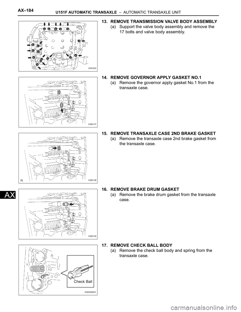
13. REMOVE TRANSMISSION VALVE BODY ASSEMBLY
(a) Support the valve body assembly and remove the
17 bolts and valve body assembly.
14. REMOVE GOVERNOR APPLY GASKET NO.1
(a) Remove the governor apply gasket No.1 from the
transaxle case.
15. REMOVE TRANSAXLE CASE 2ND BRAKE GASKET
(a) Remove the transaxle case 2nd brake gasket from
the transaxle case.
16. REMOVE BRAKE DRUM GASKET
(a) Remove the brake drum gasket from the transaxle
case.
17. REMOVE CHECK BALL BODY
(a) Remove the check ball body and spring from the
transaxle case.
C091933
C083127
C083128
C083129
D003554E01
Page 1868 of 3000
U151F AUTOMATIC TRANSAXLE – AUTOMATIC TRANSAXLE UNITAX–193
AX
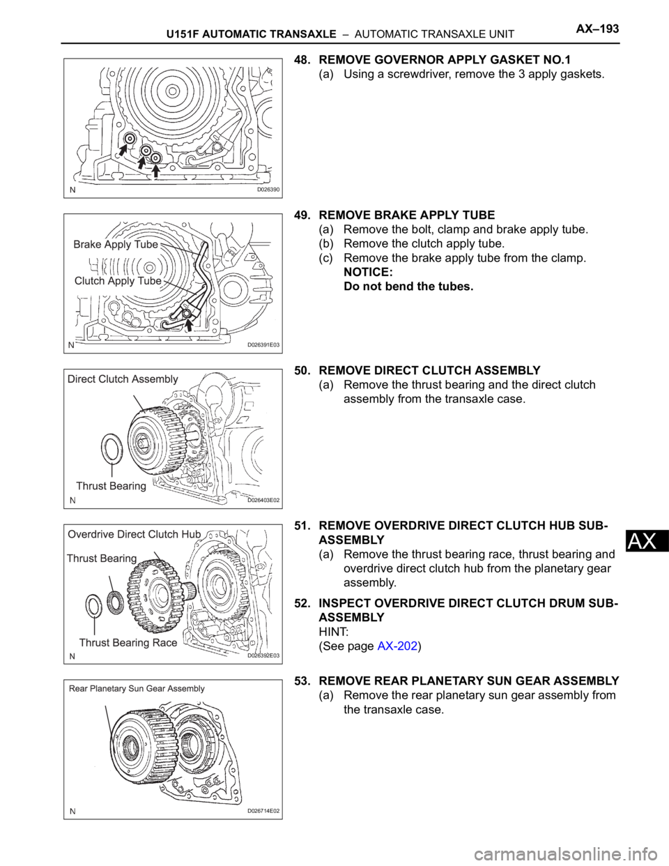
48. REMOVE GOVERNOR APPLY GASKET NO.1
(a) Using a screwdriver, remove the 3 apply gaskets.
49. REMOVE BRAKE APPLY TUBE
(a) Remove the bolt, clamp and brake apply tube.
(b) Remove the clutch apply tube.
(c) Remove the brake apply tube from the clamp.
NOTICE:
Do not bend the tubes.
50. REMOVE DIRECT CLUTCH ASSEMBLY
(a) Remove the thrust bearing and the direct clutch
assembly from the transaxle case.
51. REMOVE OVERDRIVE DIRECT CLUTCH HUB SUB-
ASSEMBLY
(a) Remove the thrust bearing race, thrust bearing and
overdrive direct clutch hub from the planetary gear
assembly.
52. INSPECT OVERDRIVE DIRECT CLUTCH DRUM SUB-
ASSEMBLY
HINT:
(See page AX-202)
53. REMOVE REAR PLANETARY SUN GEAR ASSEMBLY
(a) Remove the rear planetary sun gear assembly from
the transaxle case.
D026390
D026391E03
D026403E02
D026392E03
D026714E02