throttle Body installation TOYOTA SIENNA 2007 Service Repair Manual
[x] Cancel search | Manufacturer: TOYOTA, Model Year: 2007, Model line: SIENNA, Model: TOYOTA SIENNA 2007Pages: 3000, PDF Size: 52.26 MB
Page 22 of 3000
![TOYOTA SIENNA 2007 Service Repair Manual ES–5222GR-FE ENGINE CONTROL SYSTEM – KNOCK SENSOR
ES
(g) Using a 5 mm socket hexagon wrench, remove the
4 bolts [G].
(h) Remove the 2 nuts, 2 bolts and intake air surge tank
[H].
(i) Remove th TOYOTA SIENNA 2007 Service Repair Manual ES–5222GR-FE ENGINE CONTROL SYSTEM – KNOCK SENSOR
ES
(g) Using a 5 mm socket hexagon wrench, remove the
4 bolts [G].
(h) Remove the 2 nuts, 2 bolts and intake air surge tank
[H].
(i) Remove th](/img/14/57466/w960_57466-21.png)
ES–5222GR-FE ENGINE CONTROL SYSTEM – KNOCK SENSOR
ES
(g) Using a 5 mm socket hexagon wrench, remove the
4 bolts [G].
(h) Remove the 2 nuts, 2 bolts and intake air surge tank
[H].
(i) Remove the gasket from the intake air surge tank [I].
9. REMOVE FUEL MAIN TUBE SUB-ASSEMBLY (See
page EM-30)
10. REMOVE INTAKE MANIFOLD (See page EM-39)
11. REMOVE KNOCK CONTROL SENSOR
(a) Disconnect the 2 knock sensor connectors.
(b) Remove the 2 bolts and then remove the 2 knock
control sensors.
INSPECTION
1. KNOCK CONTROL SENSOR
(a) Using an ohmmeter, measure the resistance
between the terminals.
Resistance:
120 to 280 k
at 20C (68F)
If the resistance is not specified, replace the knock
control sensor.
INSTALLATION
1. INSTALL KNOCK CONTROL SENSOR
(a) Install the 2 knock control sensors with the 2 bolts
as shown in the illustration.
Torque: 20 N*m (204 kgf*cm, 15 ft.*lbf)
(b) Connect the 2 knock control sensor connectors.
2. INSTALL INTAKE MANIFOLD (See page EM-49)
3. INSTALL FUEL MAIN TUBE SUB-ASSEMBLY (See
page EM-56)
4. INSTALL INTAKE AIR SURGE TANK
NOTICE:
DO NOT apply oil to the bolts listed below.
A129468E08
A129615
A065174
A132951E01
Tightening PartsTo r q u e
N*m (kgf*cm, ft.*lbf)QTY
Surge Tank and Intake Manifold 18 (184, 13) 4
No. 1 Surge Tank Stay and Surge Tank 21 (214, 15) 1
Throttle Body Bracket and Surge Tank 21 (214, 15) 1
Page 791 of 3000

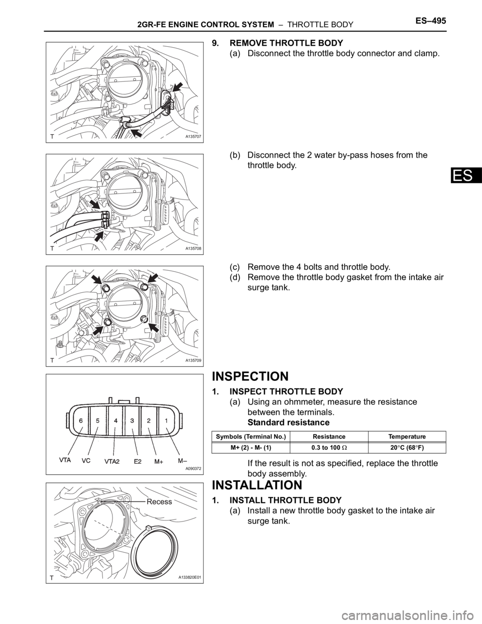
2GR-FE ENGINE CONTROL SYSTEM – THROTTLE BODYES–495
ES
9. REMOVE THROTTLE BODY
(a) Disconnect the throttle body connector and clamp.
(b) Disconnect the 2 water by-pass hoses from the
throttle body.
(c) Remove the 4 bolts and throttle body.
(d) Remove the throttle body gasket from the intake air
surge tank.
INSPECTION
1. INSPECT THROTTLE BODY
(a) Using an ohmmeter, measure the resistance
between the terminals.
Standard resistance
If the result is not as specified, replace the throttle
body assembly.
INSTALLATION
1. INSTALL THROTTLE BODY
(a) Install a new throttle body gasket to the intake air
surge tank.
A135707
A135708
A135709
A090372
Symbols (Terminal No.) Resistance Temperature
M+ (2) - M- (1) 0.3 to 100
20C (68F)
A133820E01
Page 837 of 3000
![TOYOTA SIENNA 2007 Service Repair Manual ES–5222GR-FE ENGINE CONTROL SYSTEM – KNOCK SENSOR
ES
(g) Using a 5 mm socket hexagon wrench, remove the
4 bolts [G].
(h) Remove the 2 nuts, 2 bolts and intake air surge tank
[H].
(i) Remove th TOYOTA SIENNA 2007 Service Repair Manual ES–5222GR-FE ENGINE CONTROL SYSTEM – KNOCK SENSOR
ES
(g) Using a 5 mm socket hexagon wrench, remove the
4 bolts [G].
(h) Remove the 2 nuts, 2 bolts and intake air surge tank
[H].
(i) Remove th](/img/14/57466/w960_57466-836.png)
ES–5222GR-FE ENGINE CONTROL SYSTEM – KNOCK SENSOR
ES
(g) Using a 5 mm socket hexagon wrench, remove the
4 bolts [G].
(h) Remove the 2 nuts, 2 bolts and intake air surge tank
[H].
(i) Remove the gasket from the intake air surge tank [I].
9. REMOVE FUEL MAIN TUBE SUB-ASSEMBLY (See
page EM-30)
10. REMOVE INTAKE MANIFOLD (See page EM-39)
11. REMOVE KNOCK CONTROL SENSOR
(a) Disconnect the 2 knock sensor connectors.
(b) Remove the 2 bolts and then remove the 2 knock
control sensors.
INSPECTION
1. KNOCK CONTROL SENSOR
(a) Using an ohmmeter, measure the resistance
between the terminals.
Resistance:
120 to 280 k
at 20C (68F)
If the resistance is not specified, replace the knock
control sensor.
INSTALLATION
1. INSTALL KNOCK CONTROL SENSOR
(a) Install the 2 knock control sensors with the 2 bolts
as shown in the illustration.
Torque: 20 N*m (204 kgf*cm, 15 ft.*lbf)
(b) Connect the 2 knock control sensor connectors.
2. INSTALL INTAKE MANIFOLD (See page EM-49)
3. INSTALL FUEL MAIN TUBE SUB-ASSEMBLY (See
page EM-56)
4. INSTALL INTAKE AIR SURGE TANK
NOTICE:
DO NOT apply oil to the bolts listed below.
A129468E08
A129615
A065174
A132951E01
Tightening PartsTo r q u e
N*m (kgf*cm, ft.*lbf)QTY
Surge Tank and Intake Manifold 18 (184, 13) 4
No. 1 Surge Tank Stay and Surge Tank 21 (214, 15) 1
Throttle Body Bracket and Surge Tank 21 (214, 15) 1