TOYOTA SUPRA 1986 Service Repair Manual
SUPRA 1986
TOYOTA
TOYOTA
https://www.carmanualsonline.info/img/14/57467/w960_57467-0.png
TOYOTA SUPRA 1986 Service Repair Manual
Trending: set clock, brake light, wipers, ground clearance, remote start, change time, recommended oil
Page 301 of 878
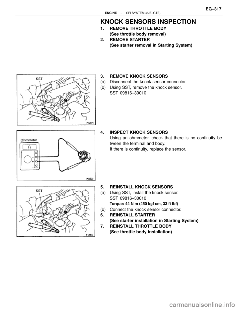
KNOCK SENSORS INSPECTION
1. REMOVE THROTTLE BODY
(See throttle body removal)
2. REMOVE STARTER
(See starter removal in Starting System)
3. REMOVE KNOCK SENSORS
(a) Disconnect the knock sensor connector.
(b) Using SST, remove the knock sensor.
SST 09816±30010
4. INSPECT KNOCK SENSORS
Using an ohmmeter, check that there is no continuity be-
tween the terminal and body.
If there is continuity, replace the sensor.
5. REINSTALL KNOCK SENSORS
(a) Using SST, install the knock sensor.
SST 09816±30010
Torque: 44 NVm (450 kgfVcm, 33 ftVlbf)
(b) Connect the knock sensor connector.
6. REINSTALL STARTER
(See starter installation in Starting System)
7. REINSTALL THROTTLE BODY
(See throttle body installation)
± ENGINESFI SYSTEM (2JZ±GTE)EG±317
Page 302 of 878
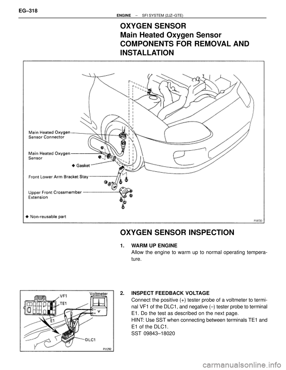
OXYGEN SENSOR
Main Heated Oxygen Sensor
COMPONENTS FOR REMOVAL AND
INSTALLATION
OXYGEN SENSOR INSPECTION
1. WARM UP ENGINE
Allow the engine to warm up to normal operating tempera-
ture.
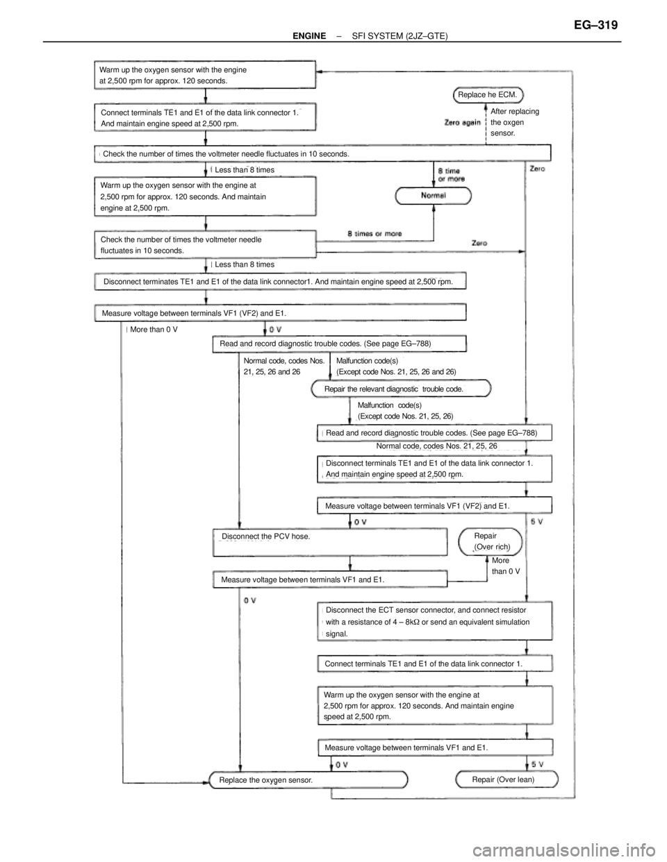
2. INSPECT FEEDBACK VOLTAGE
Connect the positive (+) tester probe of a voltmeter to termi-
nal VF1 of the DLC1, and negative (±) tester probe to terminal
E1. Do the test as described on the next page.
HINT: Use SST when connecting between terminals TE1 and
E1 of the DLC1.
SST 09843±18020 EG±318
± ENGINESFI SYSTEM (2JZ±GTE)
Page 303 of 878
(See page EG±788)
(See page EG±788)
Warm up the oxygen sensor with the engine
at 2,500 rpm for approx. 120 seconds.
Connect terminals TE1 and E1 of the data link connector 1.
And maintain engine speed at 2,500 rpm.
Check the number of times the voltmeter needle fluctuates in 10 seconds.
Less than 8 times
Warm up the oxygen sensor with the engine at
2,500 rpm for approx. 120 seconds. And maintain
engine at 2,500 rpm.
Check the number of times the voltmeter needle
fluctuates in 10 seconds.
Less than 8 times
Disconnect terminates TE1 and E1 of the data link connector1. And maintain engine speed at 2,500 rpm.
Measure voltage between terminals VF1 (VF2) and E1.
More than 0 V
Read and record diagnostic trouble codes. (See page EG±788)
Normal code, codes Nos.
21, 25, 26 and 26Malfunction code(s)
(Except code Nos. 21, 25, 26 and 26)
Repair the relevant diagnostic trouble code.
Malfunction code(s)
(Except code Nos. 21, 25, 26)
Read and record diagnostic trouble codes. (See page EG±788)
Normal code, codes Nos. 21, 25, 26
Disconnect terminals TE1 and E1 of the data link connector 1.
And maintain engine speed at 2,500 rpm.
Measure voltage between terminals VF1 (VF2) and E1.
Repair
(Over rich)
More
than 0 V
Disconnect the PCV hose.
Measure voltage between terminals VF1 and E1.
Disconnect the ECT sensor connector, and connect resistor
with a resistance of 4 ± 8k� or send an equivalent simulation
signal.
Connect terminals TE1 and E1 of the data link connector 1.
Warm up the oxygen sensor with the engine at
2,500 rpm for approx. 120 seconds. And maintain engine
speed at 2,500 rpm.
Measure voltage between terminals VF1 and E1.
Repair (Over lean)Replace the oxygen sensor.
After replacing
the oxgen
sensor.
Replace he ECM.
± ENGINESFI SYSTEM (2JZ±GTE)EG±319
Page 304 of 878
3. INSPECT HEATER RESISTANCE OF MAIN HEATED
OXYGEN SENSOR
(a) Disconnect the oxygen sensor connector.
(b) Using an ohmmeter, measure the resistance between the
terminals +B and HT.
Resistance:
At 20°C (68°F) 11±16 �
If the resistance is not as specified, replace the sensor.
Torque: 20 NVm (200 kgfVcm, 14 ftVlbf)
(c) Reconnect the oxygen sensor connector. EG±320
± ENGINESFI SYSTEM (2JZ±GTE)
Page 305 of 878
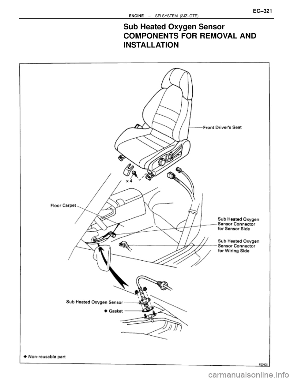
Sub Heated Oxygen Sensor
COMPONENTS FOR REMOVAL AND
INSTALLATION
± ENGINESFI SYSTEM (2JZ±GTE)EG±321
Page 306 of 878
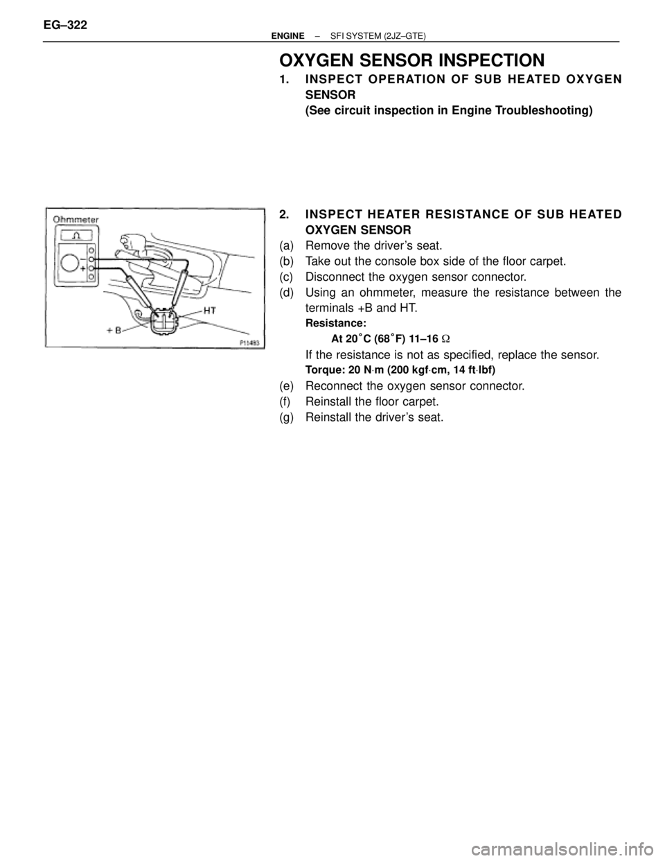
OXYGEN SENSOR INSPECTION
1. INSPECT OPERATION OF SUB HEATED OXYGEN
SENSOR
(See circuit inspection in Engine Troubleshooting)
2. INSPECT HEATER RESISTANCE OF SUB HEATED
OXYGEN SENSOR
(a) Remove the driver's seat.
(b) Take out the console box side of the floor carpet.
(c) Disconnect the oxygen sensor connector.
(d) Using an ohmmeter, measure the resistance between the
terminals +B and HT.
Resistance:
At 20°C (68°F) 11±16 �
If the resistance is not as specified, replace the sensor.
Torque: 20 NVm (200 kgfVcm, 14 ftVlbf)
(e) Reconnect the oxygen sensor connector.
(f) Reinstall the floor carpet.
(g) Reinstall the driver's seat. EG±322
± ENGINESFI SYSTEM (2JZ±GTE)
Page 307 of 878
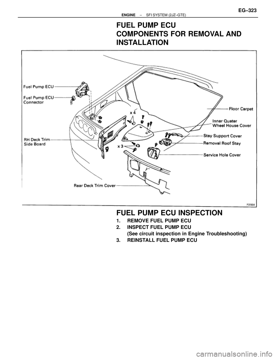
FUEL PUMP ECU
COMPONENTS FOR REMOVAL AND
INSTALLATION
FUEL PUMP ECU INSPECTION
1. REMOVE FUEL PUMP ECU
2. INSPECT FUEL PUMP ECU
(See circuit inspection in Engine Troubleshooting)
3. REINSTALL FUEL PUMP ECU
± ENGINESFI SYSTEM (2JZ±GTE)EG±323
Page 308 of 878
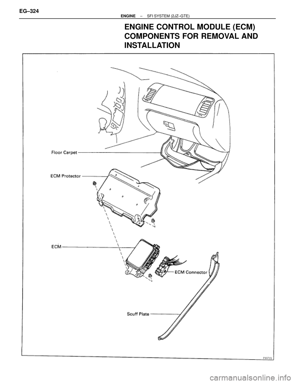
ENGINE CONTROL MODULE (ECM)
COMPONENTS FOR REMOVAL AND
INSTALLATION
EG±324± ENGINESFI SYSTEM (2JZ±GTE)
Page 309 of 878
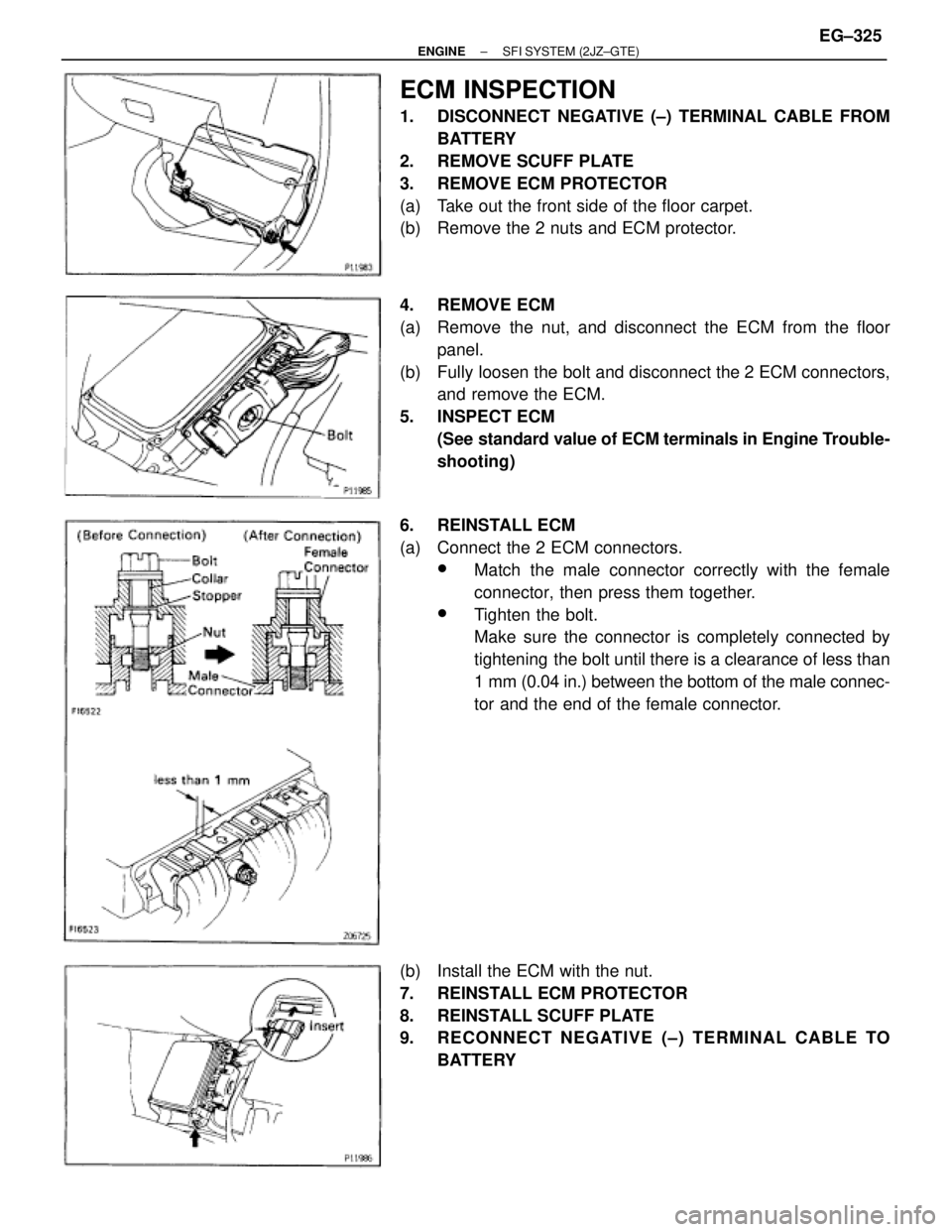
ECM INSPECTION
1. DISCONNECT NEGATIVE (±) TERMINAL CABLE FROM
BATTERY
2. REMOVE SCUFF PLATE
3. REMOVE ECM PROTECTOR
(a) Take out the front side of the floor carpet.
(b) Remove the 2 nuts and ECM protector.
4. REMOVE ECM
(a) Remove the nut, and disconnect the ECM from the floor
panel.
(b) Fully loosen the bolt and disconnect the 2 ECM connectors,
and remove the ECM.
5. INSPECT ECM
(See standard value of ECM terminals in Engine Trouble-
shooting)
6. REINSTALL ECM
(a) Connect the 2 ECM connectors.
wMatch the male connector correctly with the female
connector, then press them together.
wTighten the bolt.
Make sure the connector is completely connected by
tightening the bolt until there is a clearance of less than
1 mm (0.04 in.) between the bottom of the male connec-
tor and the end of the female connector.
(b) Install the ECM with the nut.
7. REINSTALL ECM PROTECTOR
8. REINSTALL SCUFF PLATE
9. RECONNECT NEGATIVE (±) TERMINAL CABLE TO
BATTERY
± ENGINESFI SYSTEM (2JZ±GTE)EG±325
Page 310 of 878
FUEL CUT RPM
FUEL CUT RPM INSPECTION
1. WARM UP ENGINE
Allow the engine to warm up to normal operating tempera-
ture.
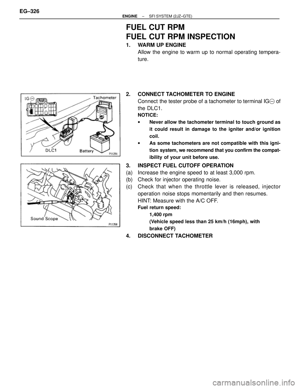
2. CONNECT TACHOMETER TO ENGINE
Connect the tester probe of a tachometer to terminal IG� of
the DLC1.
NOTICE:
wNever allow the tachometer terminal to touch ground as
it could result in damage to the igniter and/or ignition
coil.
wAs some tachometers are not compatible with this igni-
tion system, we recommend that you confirm the compat-
ibility of your unit before use.
3. INSPECT FUEL CUTOFF OPERATION
(a) Increase the engine speed to at least 3,000 rpm.
(b) Check for injector operating noise.
(c) Check that when the throttle lever is released, injector
operation noise stops momentarily and then resumes.
HINT: Measure with the A/C OFF.
Fuel return speed:
1,400 rpm
(Vehicle speed less than 25 km/h (16mph), with
brake OFF)
4. DISCONNECT TACHOMETER EG±326
± ENGINESFI SYSTEM (2JZ±GTE)
Trending: wiring diagram, fuse diagram, length, set clock, key, glove box, high beam
