TOYOTA SUPRA 1986 Service Repair Manual
SUPRA 1986
TOYOTA
TOYOTA
https://www.carmanualsonline.info/img/14/57467/w960_57467-0.png
TOYOTA SUPRA 1986 Service Repair Manual
Trending: air filter, heater, ECO mode, check engine light, coolant level, traction control, fuse diagram
Page 321 of 878
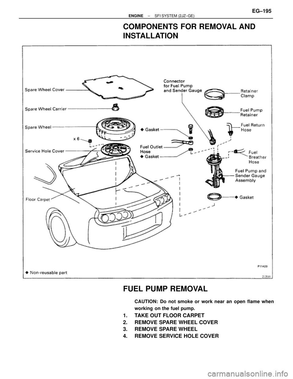
COMPONENTS FOR REMOVAL AND
INSTALLATION
FUEL PUMP REMOVAL
CAUTION: Do not smoke or work near an open flame when
working on the fuel pump.
1. TAKE OUT FLOOR CARPET
2. REMOVE SPARE WHEEL COVER
3. REMOVE SPARE WHEEL
4. REMOVE SERVICE HOLE COVER
± ENGINESFI SYSTEM (2JZ±GE)EG±195
Page 322 of 878
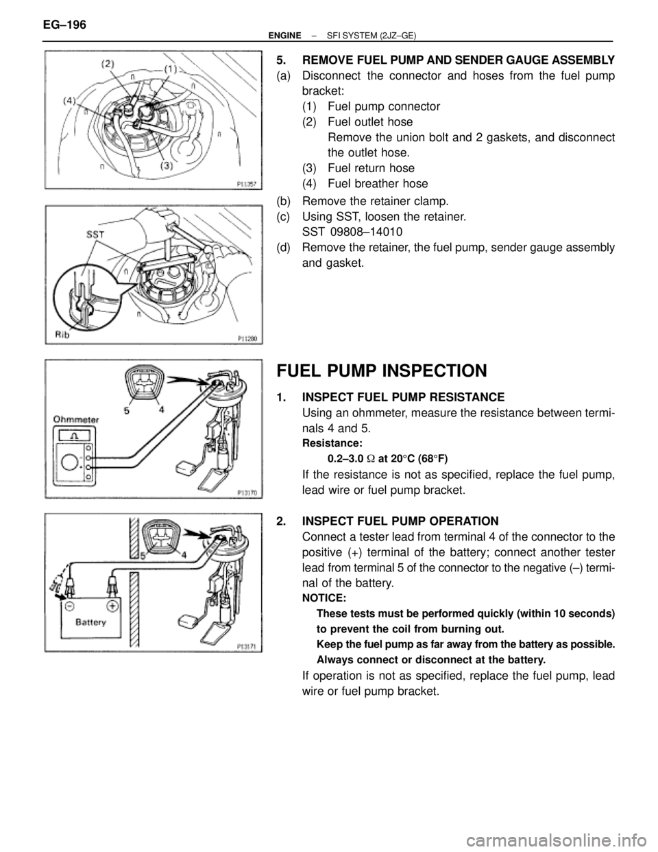
5. REMOVE FUEL PUMP AND SENDER GAUGE ASSEMBLY
(a) Disconnect the connector and hoses from the fuel pump
bracket:
(1) Fuel pump connector
(2) Fuel outlet hose
Remove the union bolt and 2 gaskets, and disconnect
the outlet hose.
(3) Fuel return hose
(4) Fuel breather hose
(b) Remove the retainer clamp.
(c) Using SST, loosen the retainer.
SST 09808±14010
(d) Remove the retainer, the fuel pump, sender gauge assembly
and gasket.
FUEL PUMP INSPECTION
1. INSPECT FUEL PUMP RESISTANCE
Using an ohmmeter, measure the resistance between termi-
nals 4 and 5.
Resistance:
0.2±3.0 � at 205C (685F)
If the resistance is not as specified, replace the fuel pump,
lead wire or fuel pump bracket.
2. INSPECT FUEL PUMP OPERATION
Connect a tester lead from terminal 4 of the connector to the
positive (+) terminal of the battery; connect another tester
lead from terminal 5 of the connector to the negative (±) termi-
nal of the battery.
NOTICE:
� These tests must be performed quickly (within 10 seconds)
to prevent the coil from burning out.
� Keep the fuel pump as far away from the battery as possible.
� Always connect or disconnect at the battery.
If operation is not as specified, replace the fuel pump, lead
wire or fuel pump bracket. EG±196
± ENGINESFI SYSTEM (2JZ±GE)
Page 323 of 878
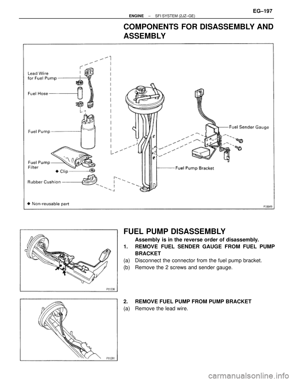
COMPONENTS FOR DISASSEMBLY AND
ASSEMBLY
FUEL PUMP DISASSEMBLY
Assembly is in the reverse order of disassembly.
1. REMOVE FUEL SENDER GAUGE FROM FUEL PUMP
BRACKET
(a) Disconnect the connector from the fuel pump bracket.
(b) Remove the 2 screws and sender gauge.
2. REMOVE FUEL PUMP FROM PUMP BRACKET
(a) Remove the lead wire.
± ENGINESFI SYSTEM (2JZ±GE)EG±197
Page 324 of 878
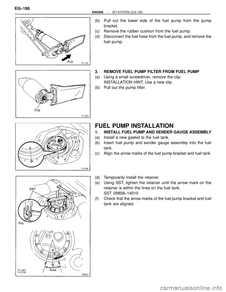
(b) Pull out the lower side of the fuel pump from the pump
bracket.
(c) Remove the rubber cushion from the fuel pump.
(d) Disconnect the fuel hose from the fuel pump, and remove the
fuel pump.
3. REMOVE FUEL PUMP FILTER FROM FUEL PUMP
(a) Using a small screwdriver, remove the clip.
INSTALLATION HINT: Use a new clip.
(b) Pull out the pump filter.
FUEL PUMP INSTALLATION
1. INSTALL FUEL PUMP AND SENDER GAUGE ASSEMBLY
(a) Install a new gasket to the fuel tank.
(b) Insert fuel pump and sender gauge assembly into the fuel
tank.
(c) Align the arrow marks of the fuel pump bracket and fuel tank.
(d) Temporarily install the retainer.
(e) Using SST, tighten the retainer until the arrow mark on the
retainer is within the lines on the fuel tank.
SST 09808±14010
(f) Check that the arrow marks of the fuel pump bracket and fuel
tank are aligned. EG±198
± ENGINESFI SYSTEM (2JZ±GE)
Page 325 of 878
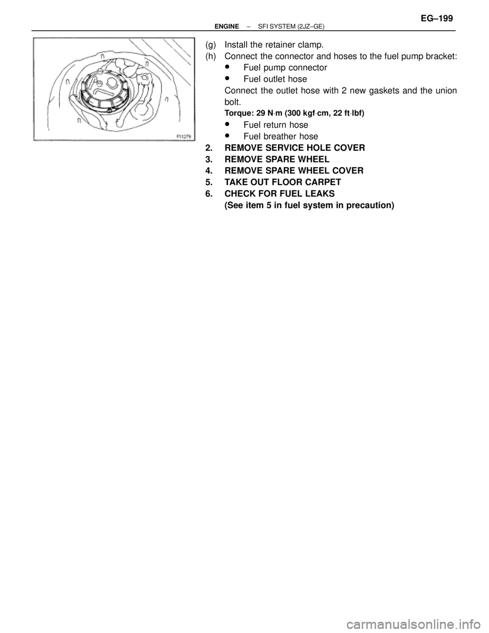
(g) Install the retainer clamp.
(h) Connect the connector and hoses to the fuel pump bracket:
wFuel pump connector
wFuel outlet hose
Connect the outlet hose with 2 new gaskets and the union
bolt.
Torque: 29 NVm (300 kgfVcm, 22 ftVlbf)
wFuel return hose
wFuel breather hose
2. REMOVE SERVICE HOLE COVER
3. REMOVE SPARE WHEEL
4. REMOVE SPARE WHEEL COVER
5. TAKE OUT FLOOR CARPET
6. CHECK FOR FUEL LEAKS
(See item 5 in fuel system in precaution)
± ENGINESFI SYSTEM (2JZ±GE)EG±199
Page 326 of 878
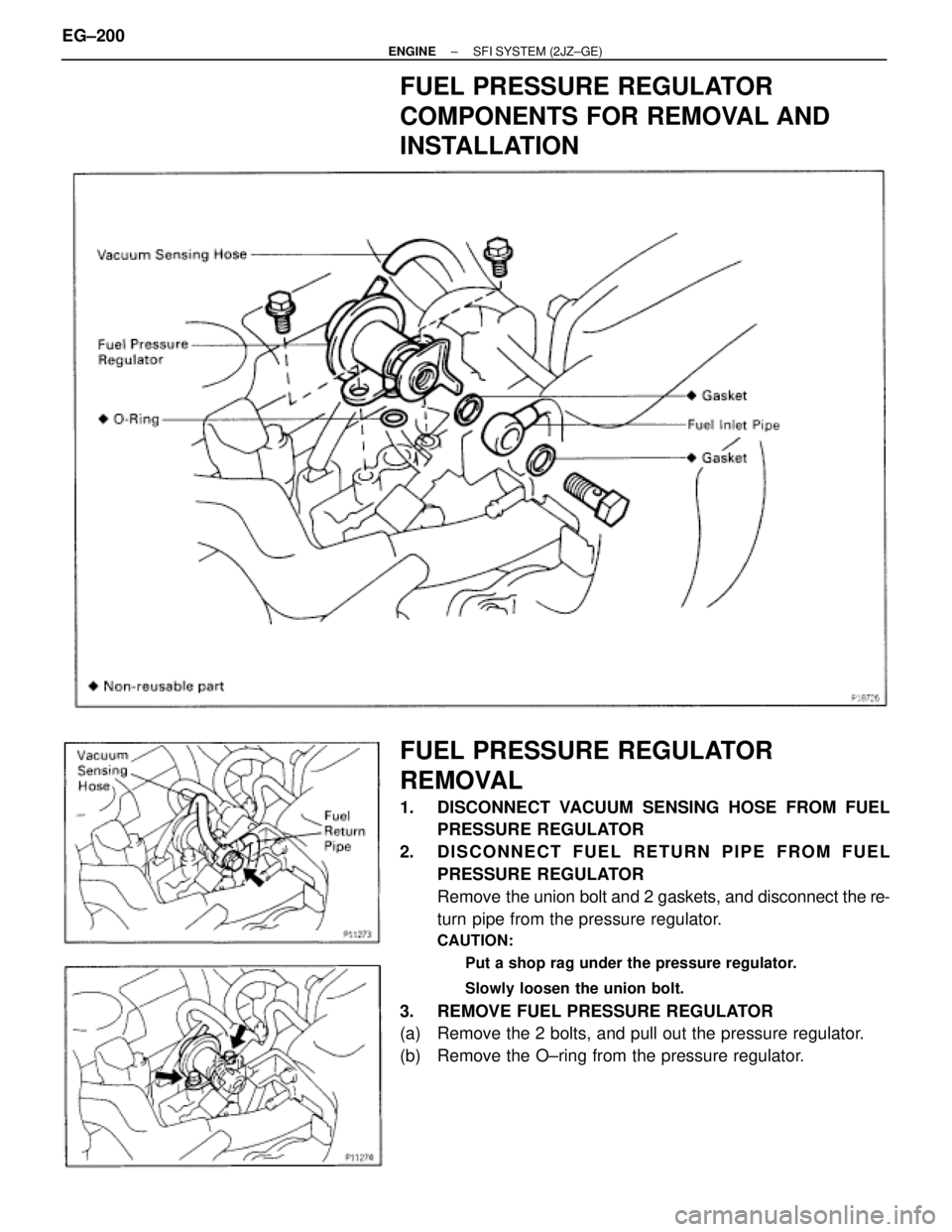
FUEL PRESSURE REGULATOR
COMPONENTS FOR REMOVAL AND
INSTALLATION
FUEL PRESSURE REGULATOR
REMOVAL
1. DISCONNECT VACUUM SENSING HOSE FROM FUEL
PRESSURE REGULATOR
2. DISCONNECT FUEL RETURN PIPE FROM FUEL
PRESSURE REGULATOR
Remove the union bolt and 2 gaskets, and disconnect the re-
turn pipe from the pressure regulator.
CAUTION:
� Put a shop rag under the pressure regulator.
� Slowly loosen the union bolt.
3. REMOVE FUEL PRESSURE REGULATOR
(a) Remove the 2 bolts, and pull out the pressure regulator.
(b) Remove the O±ring from the pressure regulator. EG±200
± ENGINESFI SYSTEM (2JZ±GE)
Page 327 of 878
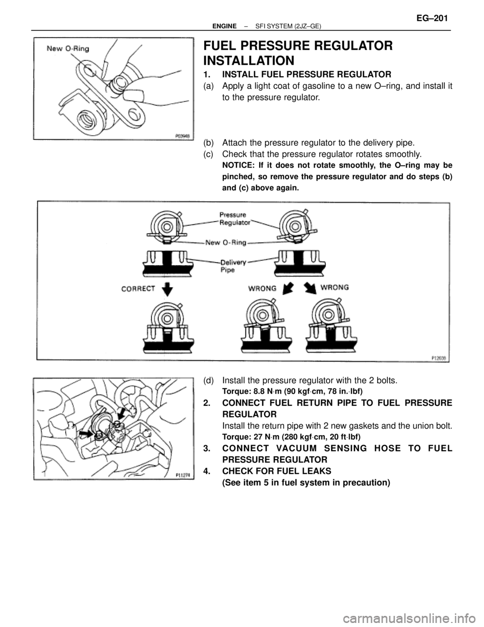
FUEL PRESSURE REGULATOR
INSTALLATION
1. INSTALL FUEL PRESSURE REGULATOR
(a) Apply a light coat of gasoline to a new O±ring, and install it
to the pressure regulator.
(b) Attach the pressure regulator to the delivery pipe.
(c) Check that the pressure regulator rotates smoothly.
NOTICE: If it does not rotate smoothly, the O±ring may be
pinched, so remove the pressure regulator and do steps (b)
and (c) above again.
(d) Install the pressure regulator with the 2 bolts.
Torque: 8.8 NVm (90 kgfVcm, 78 in.Vlbf)
2. CONNECT FUEL RETURN PIPE TO FUEL PRESSURE
REGULATOR
Install the return pipe with 2 new gaskets and the union bolt.
Torque: 27 NVm (280 kgfVcm, 20 ftVlbf)
3. CONNECT VACUUM SENSING HOSE TO FUEL
PRESSURE REGULATOR
4. CHECK FOR FUEL LEAKS
(See item 5 in fuel system in precaution)
± ENGINESFI SYSTEM (2JZ±GE)EG±201
Page 328 of 878
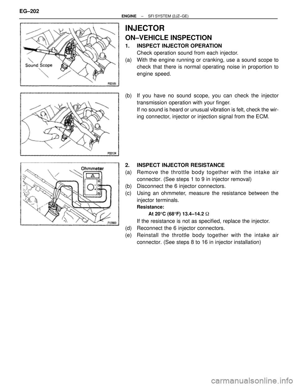
INJECTOR
ON±VEHICLE INSPECTION
1. INSPECT INJECTOR OPERATION
Check operation sound from each injector.
(a) With the engine running or cranking, use a sound scope to
check that there is normal operating noise in proportion to
engine speed.
(b) If you have no sound scope, you can check the injector
transmission operation with your finger.
If no sound is heard or unusual vibration is felt, check the wir-
ing connector, injector or injection signal from the ECM.
2. INSPECT INJECTOR RESISTANCE
(a) Re mo ve th e th ro ttle bo d y together with the intake air
connector. (See steps 1 to 9 in injector removal)
(b) Disconnect the 6 injector connectors.
(c) Using an ohmmeter, measure the resistance between the
injector terminals.
Resistance:
At 205C (685F) 13.4±14.2 �
If the resistance is not as specified, replace the injector.
(d) Reconnect the 6 injector connectors.
(e) Reinstall the throttle body together with the intake air
connector. (See steps 8 to 16 in injector installation) EG±202
± ENGINESFI SYSTEM (2JZ±GE)
Page 329 of 878
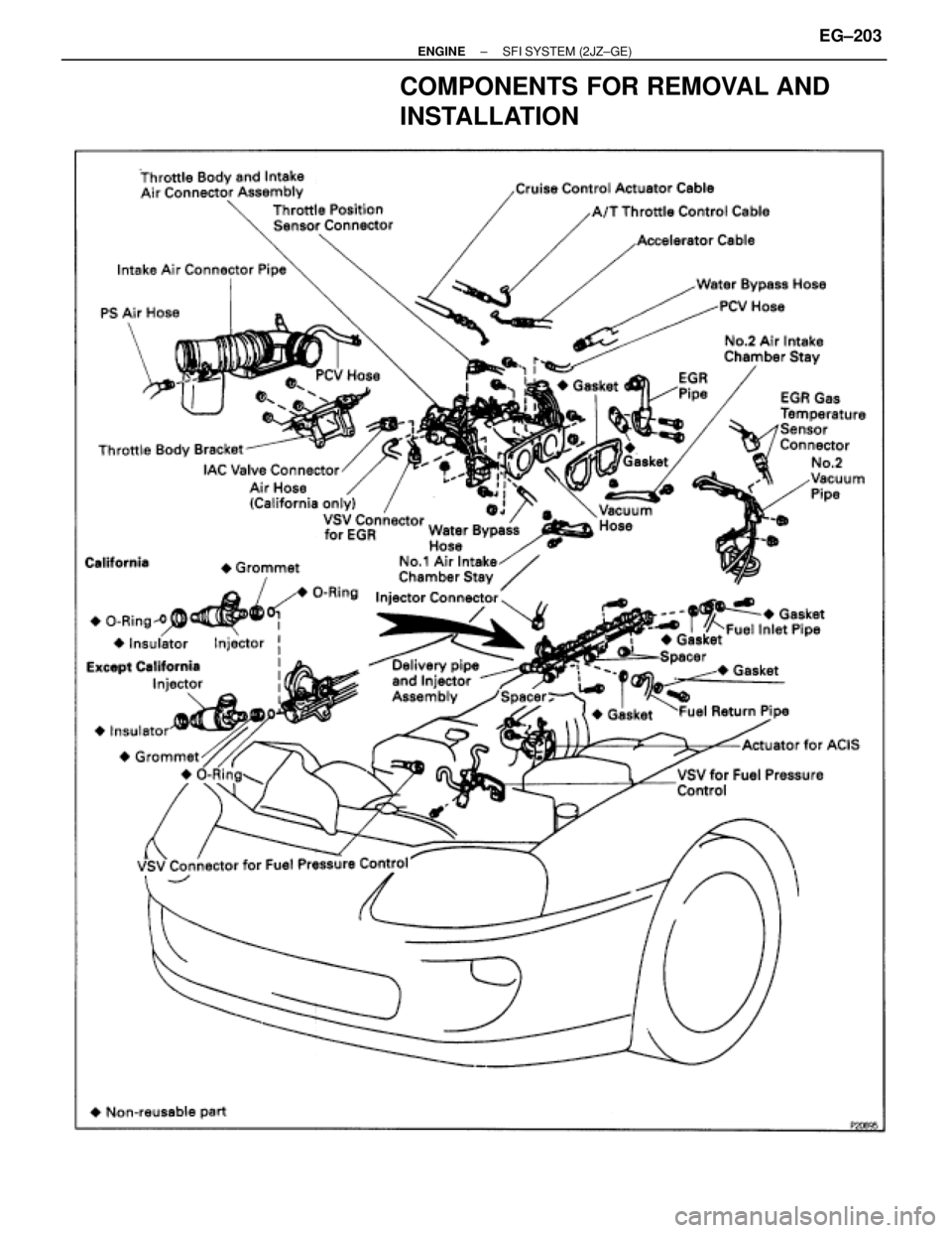
COMPONENTS FOR REMOVAL AND
INSTALLATION
± ENGINESFI SYSTEM (2JZ±GE)EG±203
Page 330 of 878
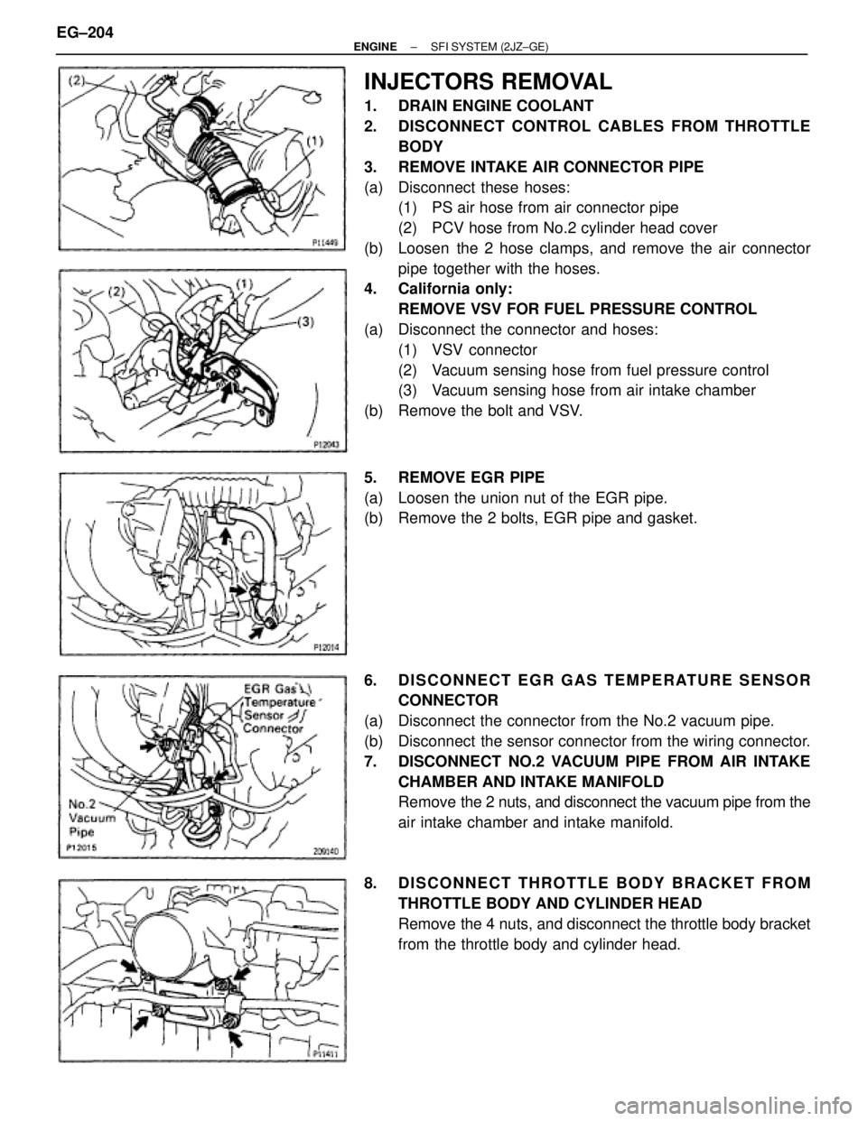
INJECTORS REMOVAL
1. DRAIN ENGINE COOLANT
2. DISCONNECT CONTROL CABLES FROM THROTTLE
BODY
3. REMOVE INTAKE AIR CONNECTOR PIPE
(a) Disconnect these hoses:
(1) PS air hose from air connector pipe
(2) PCV hose from No.2 cylinder head cover
(b) Loosen the 2 hose clamps, and remove the air connector
pipe together with the hoses.
4. California only:
REMOVE VSV FOR FUEL PRESSURE CONTROL
(a) Disconnect the connector and hoses:
(1) VSV connector
(2) Vacuum sensing hose from fuel pressure control
(3) Vacuum sensing hose from air intake chamber
(b) Remove the bolt and VSV.
5. REMOVE EGR PIPE
(a) Loosen the union nut of the EGR pipe.
(b) Remove the 2 bolts, EGR pipe and gasket.
6. DISCONNECT EGR GAS TEMPERATURE SENSOR
CONNECTOR
(a) Disconnect the connector from the No.2 vacuum pipe.
(b) Disconnect the sensor connector from the wiring connector.
7. DISCONNECT NO.2 VACUUM PIPE FROM AIR INTAKE
CHAMBER AND INTAKE MANIFOLD
Remove the 2 nuts, and disconnect the vacuum pipe from the
air intake chamber and intake manifold.
8. DISCONNECT THROTTLE BODY BRACKET FROM
THROTTLE BODY AND CYLINDER HEAD
Remove the 4 nuts, and disconnect the throttle body bracket
from the throttle body and cylinder head. EG±204
± ENGINESFI SYSTEM (2JZ±GE)
Trending: traction control, alternator, fuse box location, torque, audio, steering, warning
