TOYOTA SUPRA 1986 Service Repair Manual
SUPRA 1986
TOYOTA
TOYOTA
https://www.carmanualsonline.info/img/14/57467/w960_57467-0.png
TOYOTA SUPRA 1986 Service Repair Manual
Trending: heater, coolant, clock, wiring, fuel pump, Taillights, timing belt
Page 451 of 878
19. INSTALL WATER BYPASS OUTLET AND NO.1 WATER
BYPASS PIPE
(See step 3 in water pump installation in Cooling System)
20. INSTALL TIMING BELT
(See steps 11 to 17 in timing belt removal)
21. INSTALL SPARK PLUGS
22. INSTALL DISTRIBUTOR AND CORDS ASSEMBLY
(See steps 2, 3 and 5 in distributor installation in Ignition
System)
23. CONNECT HIGH±TENSION CORDS TO CYLINDER HEAD
COVERS
(See step 1 in high±tension cords and cord clamps
installation in Ignition System)
24. INSTALL NO.3 TIMING BELT COVER
25. INSTALL CYLINDER HEAD REAR COVER
26. INSTALL NO.2 VACUUM PIPE AND VSV ASSEMBLY
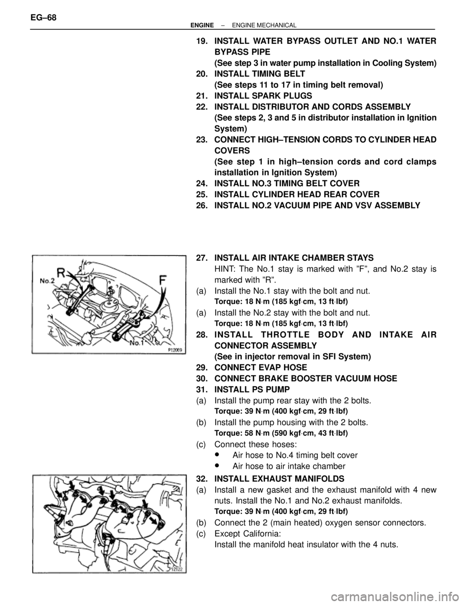
27. INSTALL AIR INTAKE CHAMBER STAYS
HINT: The No.1 stay is marked with ºFº, and No.2 stay is
marked with ºRº.
(a) Install the No.1 stay with the bolt and nut.
Torque: 18 NVm (185 kgfVcm, 13 ftVlbf)
(a) Install the No.2 stay with the bolt and nut.
Torque: 18 NVm (185 kgfVcm, 13 ftVlbf)
28. I N S TA L L T H R OTTLE BODY AND INTAKE AIR
CONNECTOR ASSEMBLY
(See in injector removal in SFI System)
29. CONNECT EVAP HOSE
30. CONNECT BRAKE BOOSTER VACUUM HOSE
31. INSTALL PS PUMP
(a) Install the pump rear stay with the 2 bolts.
Torque: 39 NVm (400 kgfVcm, 29 ftVlbf)
(b) Install the pump housing with the 2 bolts.
Torque: 58 NVm (590 kgfVcm, 43 ftVlbf)
(c) Connect these hoses:
wAir hose to No.4 timing belt cover
wAir hose to air intake chamber
32. INSTALL EXHAUST MANIFOLDS
(a) Install a new gasket and the exhaust manifold with 4 new
nuts. Install the No.1 and No.2 exhaust manifolds.
Torque: 39 NVm (400 kgfVcm, 29 ftVlbf)
(b) Connect the 2 (main heated) oxygen sensor connectors.
(c) Except California:
Install the manifold heat insulator with the 4 nuts. EG±68
± ENGINEENGINE MECHANICAL
Page 452 of 878
33. INSTALL NO.2 FRONT EXHAUST PIPE
(See step 6 in engine installation in Engine Mechanical)
34. INSTALL DRIVE BELT
35. INSTALL AIR CLEANER, VAF METER AND INTAKE AIR
CONNECTOR PIPE ASSEMBLY
(See step 22 in engine installation in Engine Mechanical)
36. INSTALL AIR CLEANER DUCT
37. FILL WITH ENGINE COOLANT
38. START ENGINE AND CHECK FOR LEAKS
39. CHECK IGNITION TIMING
(See steps 8 to 12 in distributor installation in Ignition
System)
40. INSTALL ENGINE UNDER COVER
41. PERFORM ROAD TEST
Check for abnormal noise, shock, slippage, correct shift
points and smooth operation.
42. RECHECK ENGINE COOLANT LEVEL
CYLINDER HEAD INSTALLATION
(2JZ±GTE)
1. INSTALL CYLINDER HEAD
(See step 1 in cylinder head installation (2JZ±GE))
2. INSTALL CAMSHAFTS
(See step 2 ((a) to (m)) in cylinder head installation (2JZ±
GE))
3. CHECK AND ADJUST VALVE CLEARANCE
(See steps 5 to 6 in valve clearance inspection and ad-
justment)
Turn the camshaft, and position the cam lobe upward, check
and adjust the valve clearance.
4. INSTALL NO.4 TIMING BELT COVER
(See step 4 in cylinder head installation (2JZ±GE))
5. INSTALL CAMSHAFT TIMING PULLEYS
(See step 5 in cylinder head installation (2JZ±GE))
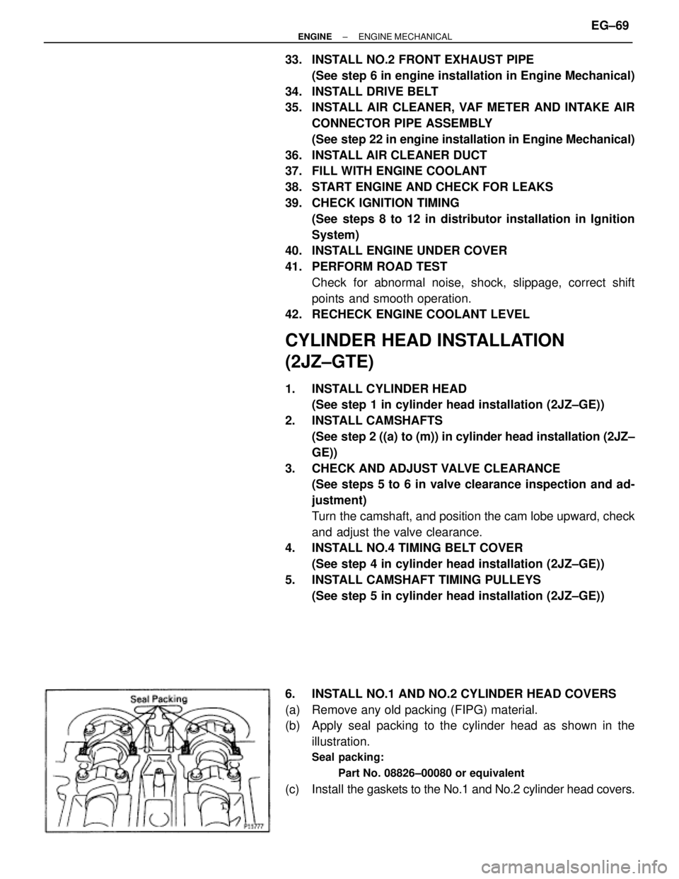
6. INSTALL NO.1 AND NO.2 CYLINDER HEAD COVERS
(a) Remove any old packing (FIPG) material.
(b) Apply seal packing to the cylinder head as shown in the
illustration.
Seal packing:
Part No. 08826±00080 or equivalent
(c) Install the gaskets to the No.1 and No.2 cylinder head covers.
± ENGINEENGINE MECHANICALEG±69
Page 453 of 878
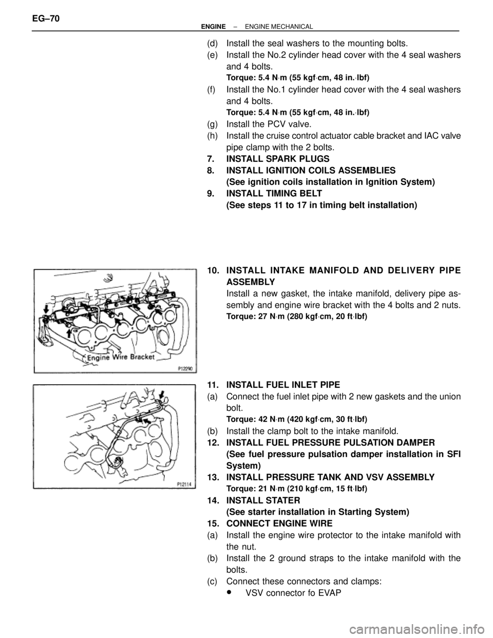
(d) Install the seal washers to the mounting bolts.
(e) Install the No.2 cylinder head cover with the 4 seal washers
and 4 bolts.
Torque: 5.4 NVm (55 kgfVcm, 48 in.Vlbf)
(f) Install the No.1 cylinder head cover with the 4 seal washers
and 4 bolts.
Torque: 5.4 NVm (55 kgfVcm, 48 in.Vlbf)
(g) Install the PCV valve.
(h) Install the cruise control actuator cable bracket and IAC valve
pipe clamp with the 2 bolts.
7. INSTALL SPARK PLUGS
8. INSTALL IGNITION COILS ASSEMBLIES
(See ignition coils installation in Ignition System)
9. INSTALL TIMING BELT
(See steps 11 to 17 in timing belt installation)
10. INS TALL INTAKE MANIFO LD AND DE LIV E RY PIP E
ASSEMBLY
Install a new gasket, the intake manifold, delivery pipe as-
sembly and engine wire bracket with the 4 bolts and 2 nuts.
Torque: 27 NVm (280 kgfVcm, 20 ftVlbf)
11. INSTALL FUEL INLET PIPE
(a) Connect the fuel inlet pipe with 2 new gaskets and the union
bolt.
Torque: 42 NVm (420 kgfVcm, 30 ftVlbf)
(b) Install the clamp bolt to the intake manifold.
12. INSTALL FUEL PRESSURE PULSATION DAMPER
(See fuel pressure pulsation damper installation in SFI
System)
13. INSTALL PRESSURE TANK AND VSV ASSEMBLY
Torque: 21 NVm (210 kgfVcm, 15 ftVlbf)
14. INSTALL STATER
(See starter installation in Starting System)
15. CONNECT ENGINE WIRE
(a) Install the engine wire protector to the intake manifold with
the nut.
(b) Install the 2 ground straps to the intake manifold with the
bolts.
(c) Connect these connectors and clamps:
wVSV connector fo EVAP EG±70
± ENGINEENGINE MECHANICAL
Page 454 of 878
w6 injectors connectors
HINT: The No.1, No.3 and No.5 injector connectors are dark
gray, and the No.2, No.4 and No.6 injector connectors are
gray.
w2 camshaft position sensor connectors
w3 engine wire clamps to injector holders
16. INSTALL AIR INTAKE CHAMBER ASSEMBLY
(See injector installation in SFI System)
17. CONNECT FUEL RETURN HOSE
18. INSTALL PS PUMP
Torque: 58 NVm (590 kgfVcm, 43 ftVlbf)
19. INSTALL WATER OUTLET AND NO.1 WATER BYPASS
PIPE
(a) Install 2 new O±rings to the No.1 water bypass pipe.
(b) Apply soapy water to the O±rings.
(c) Install the No.1 water bypass pipe to the water pump.
(d) Install a new gasket and the water outlet with the 2 bolts.
Torque: 21 NVm (210 kgfVcm, 15 ftVlbf)
(e) Connect the ECT sensor and sender gauge connectors.
(f) Connect the upper radiator hose to the water outlet.
20. INSTALL DRIVE BELT
Install the drive belt by turning the drive belt tensioner clock-
wise.
21. M/T:
INSTALL DRIVE BELT TENSIONER DAMPER
(See step 19 in timing belt installation)
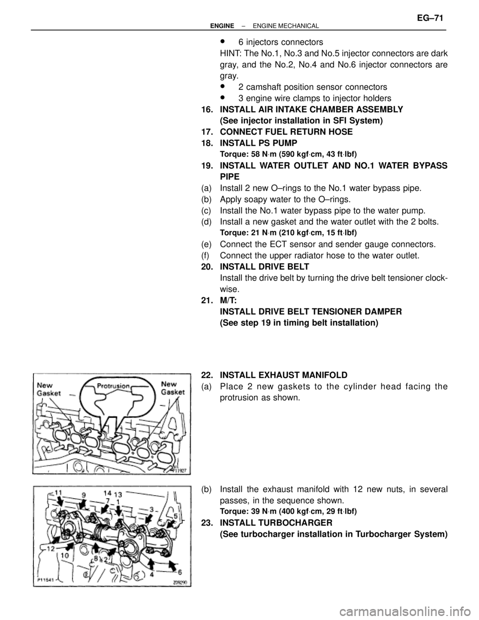
22. INSTALL EXHAUST MANIFOLD
(a) P la ce 2 ne w ga ske ts to th e cylinder head facing the
protrusion as shown.
(b) Install the exhaust manifold with 12 new nuts, in several
passes, in the sequence shown.
Torque: 39 NVm (400 kgfVcm, 29 ftVlbf)
23. INSTALL TURBOCHARGER
(See turbocharger installation in Turbocharger System)
± ENGINEENGINE MECHANICALEG±71
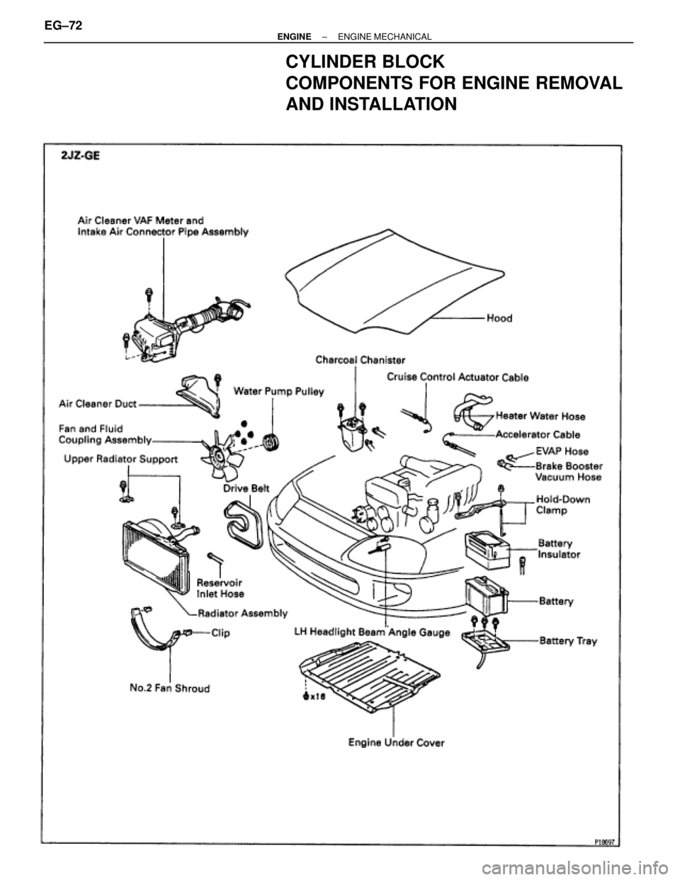
Page 455 of 878
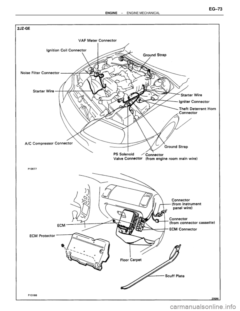
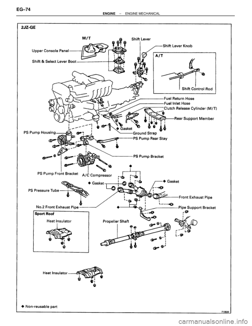
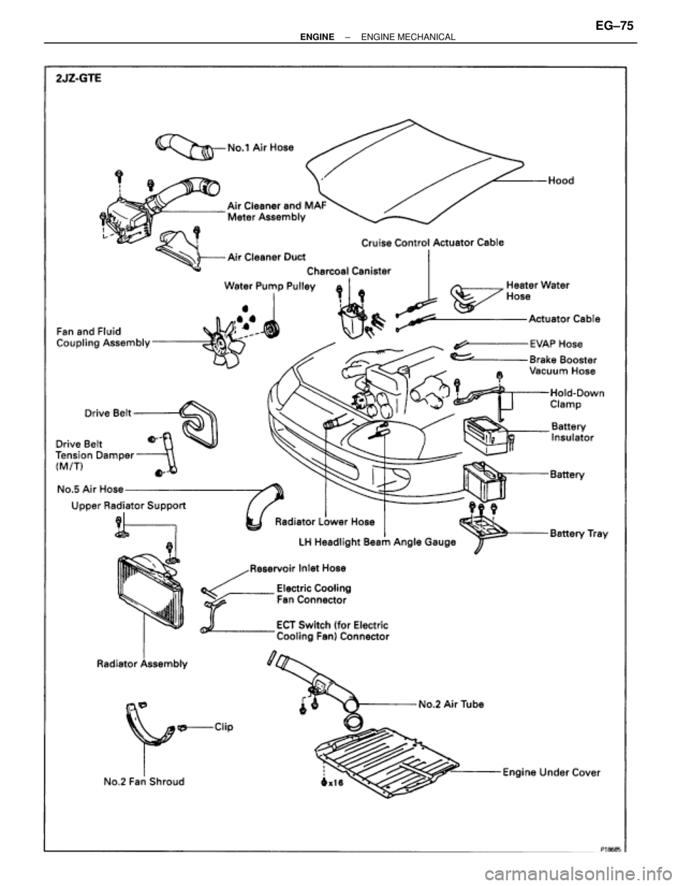
CYLINDER BLOCK
COMPONENTS FOR ENGINE REMOVAL
AND INSTALLATION
EG±72± ENGINEENGINE MECHANICAL
Page 456 of 878
± ENGINEENGINE MECHANICALEG±73
Page 457 of 878
EG±74± ENGINEENGINE MECHANICAL
Page 458 of 878
± ENGINEENGINE MECHANICALEG±75
Page 459 of 878
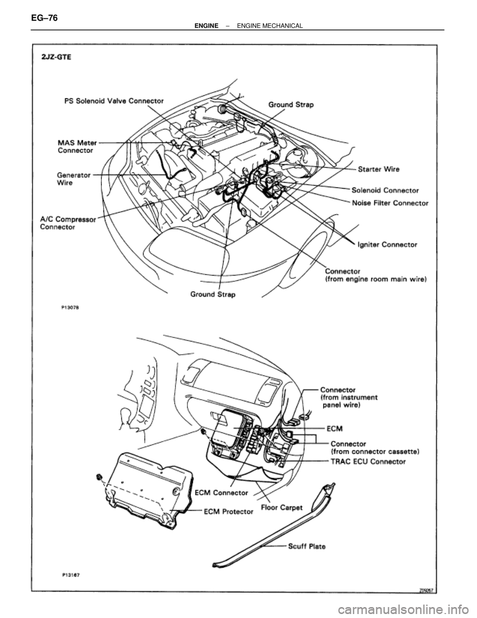
EG±76± ENGINEENGINE MECHANICAL
Page 460 of 878
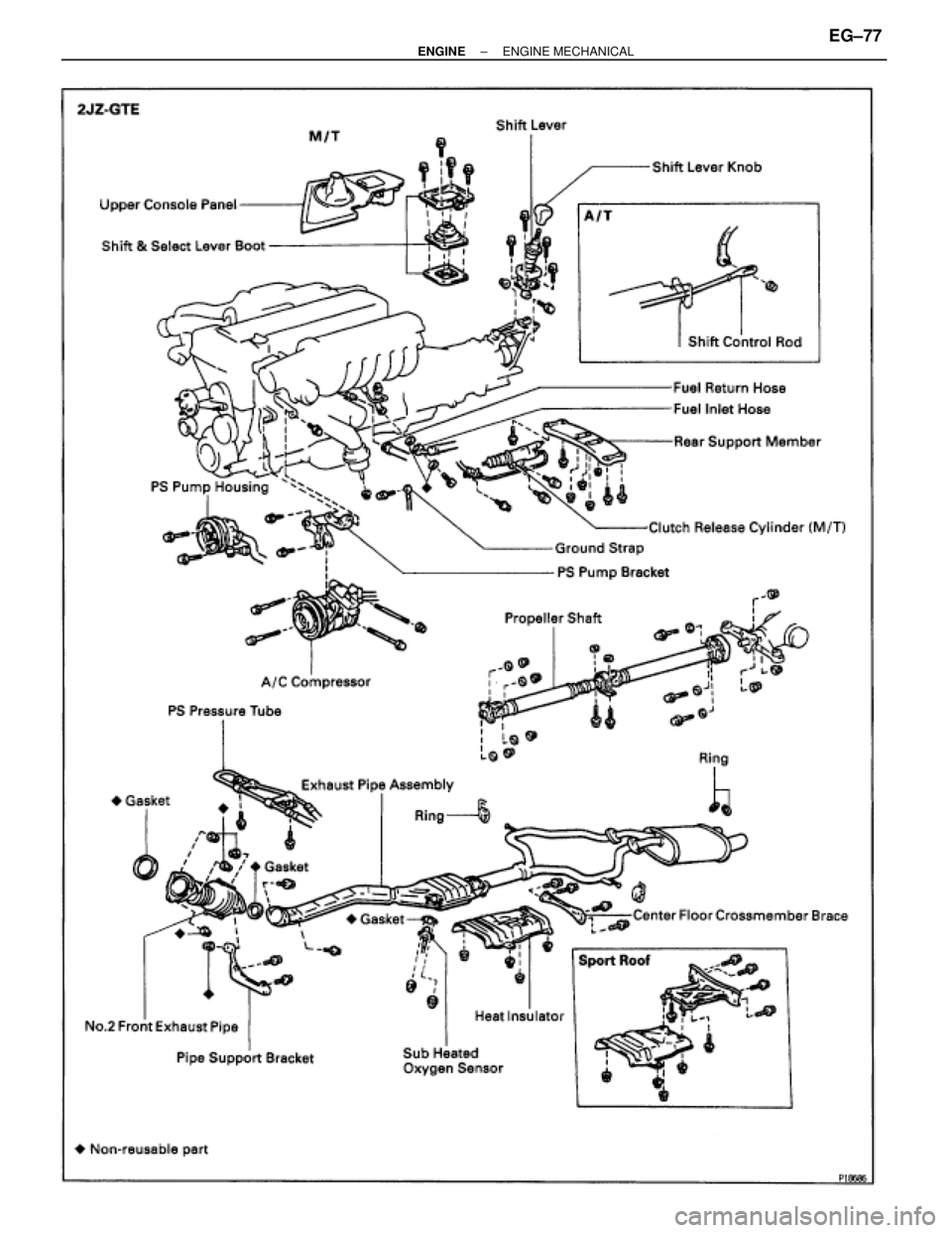
± ENGINEENGINE MECHANICALEG±77
Trending: fuse box, roof rack, power steering, turn signal, warning, light, fuse chart


