TOYOTA SUPRA 1995 Service Repair Manual
Manufacturer: TOYOTA, Model Year: 1995, Model line: SUPRA, Model: TOYOTA SUPRA 1995Pages: 2543, PDF Size: 53.25 MB
Page 501 of 2543
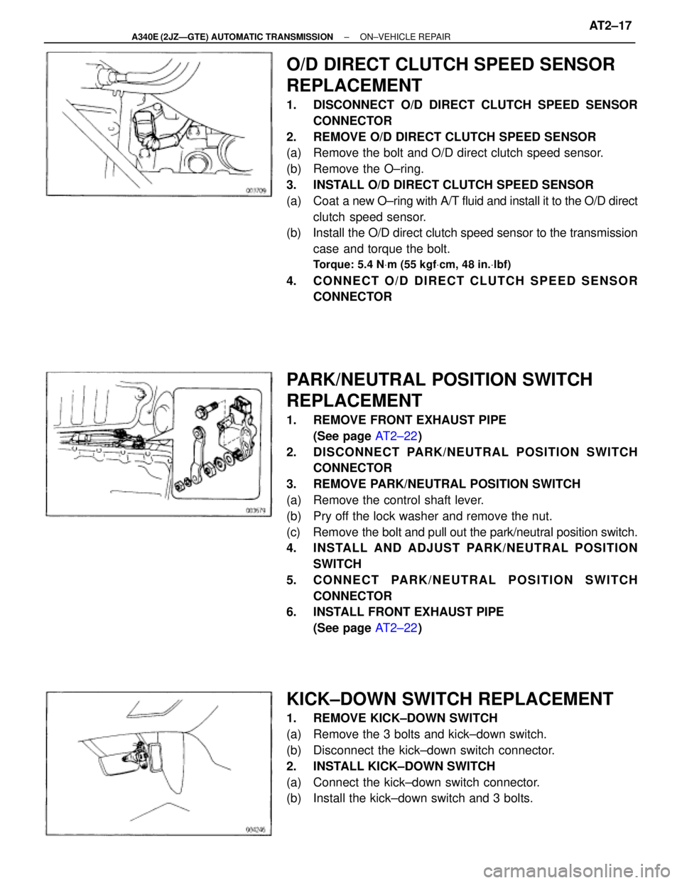
O/D DIRECT CLUTCH SPEED SENSOR
REPLACEMENT
1. DISCONNECT O/D DIRECT CLUTCH SPEED SENSOR
CONNECTOR
2. REMOVE O/D DIRECT CLUTCH SPEED SENSOR
(a) Remove the bolt and O/D direct clutch speed sensor.
(b) Remove the O±ring.
3. INSTALL O/D DIRECT CLUTCH SPEED SENSOR
(a) Coat a new O±ring with A/T fluid and install it to the O/D direct
clutch speed sensor.
(b) Install the O/D direct clutch speed sensor to the transmission
case and torque the bolt.
Torque: 5.4 NVm (55 kgfVcm, 48 in.Vlbf)
4. CONNECT O/D DIRECT CLUTCH SPEED SENSOR
CONNECTOR
PARK/NEUTRAL POSITION SWITCH
REPLACEMENT
1. REMOVE FRONT EXHAUST PIPE
(See page AT2±22)
2. DISCONNECT PARK/NEUTRAL POSITION SWITCH
CONNECTOR
3. REMOVE PARK/NEUTRAL POSITION SWITCH
(a) Remove the control shaft lever.
(b) Pry off the lock washer and remove the nut.
(c) Remove the bolt and pull out the park/neutral position switch.
4. INSTALL AND ADJUST PARK/NEUTRAL POSITION
SWITCH
5. CONNECT PARK/NEUTRAL POSITION SWITCH
CONNECTOR
6. INSTALL FRONT EXHAUST PIPE
(See page AT2±22)
KICK±DOWN SWITCH REPLACEMENT
1. REMOVE KICK±DOWN SWITCH
(a) Remove the 3 bolts and kick±down switch.
(b) Disconnect the kick±down switch connector.
2. INSTALL KICK±DOWN SWITCH
(a) Connect the kick±down switch connector.
(b) Install the kick±down switch and 3 bolts.
± A340E (2JZÐGTE) AUTOMATIC TRANSMISSIONON±VEHICLE REPAIRAT2±17
Page 502 of 2543
VALVE BODY REMOVAL
Installation is in the reverse order of removal.
INSTALLATION HINT: After installation, fill A/T fluid and
check fluid level. (See page AT2±42)
1. DRAIN A/T FLUID
2. REMOVE EXHAUST PIPE
(See page AT2±22)
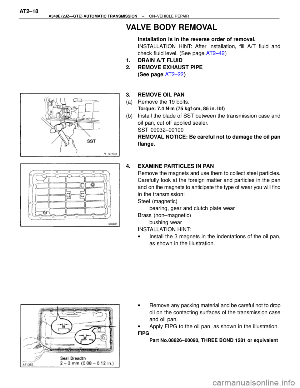
3. REMOVE OIL PAN
(a) Remove the 19 bolts.
Torque: 7.4 NVm (75 kgfVcm, 85 in.Vlbf)
(b) Install the blade of SST between the transmission case and
oil pan, cut off applied sealer.
SST 09032±00100
REMOVAL NOTICE: Be careful not to damage the oil pan
flange.
4. EXAMINE PARTICLES IN PAN
Remove the magnets and use them to collect steel particles.
Carefully look at the foreign matter and particles in the pan
and on the magnets to anticipate the type of wear you will find
in the transmission:
Steel (magnetic)
bearing, gear and clutch plate wear
Brass (non±magnetic)
bushing wear
INSTALLATION HINT:
wInstall the 3 magnets in the indentations of the oil pan,
as shown in the illustration.
wRemove any packing material and be careful not to drop
oil on the contacting surfaces of the transmission case
and oil pan.
wApply FIPG to the oil pan, as shown in the illustration.
FIPG
Part No.08826±00090, THREE BOND 1281 or equivalent
AT2±18± A340E (2JZÐGTE) AUTOMATIC TRANSMISSIONON±VEHICLE REPAIR
Page 503 of 2543
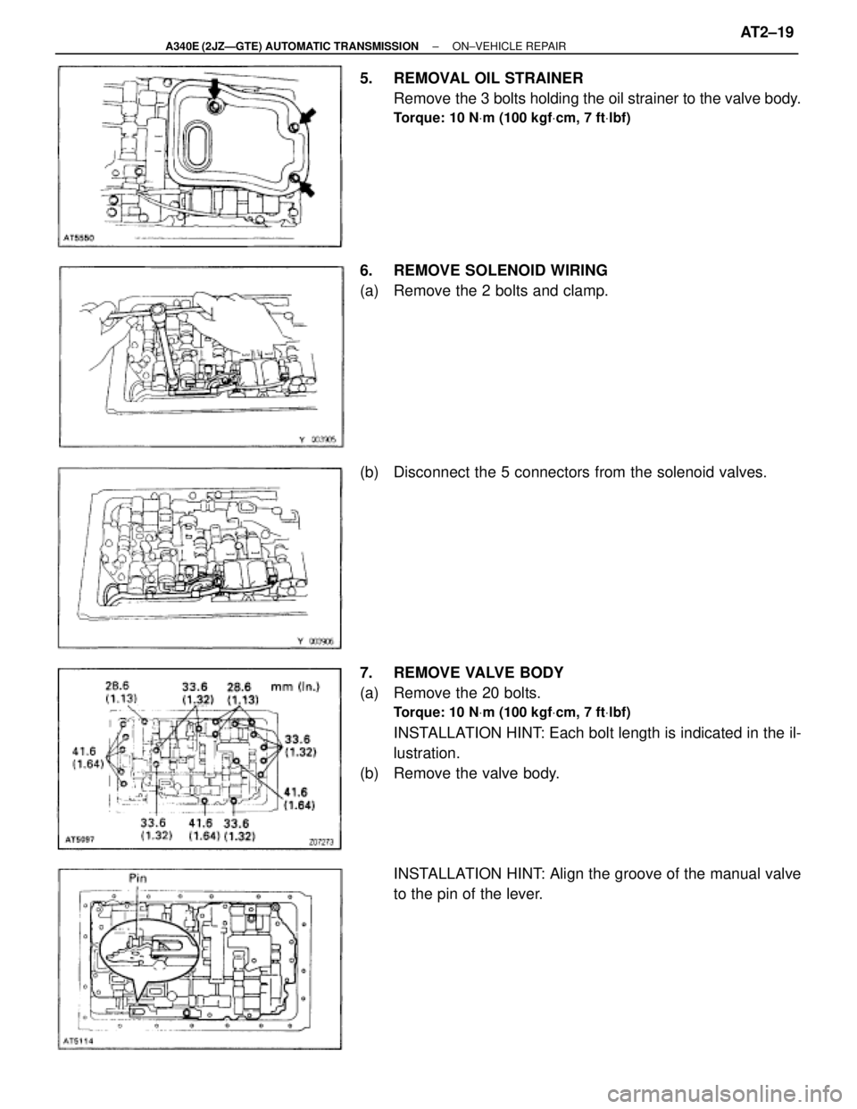
5. REMOVAL OIL STRAINER
Remove the 3 bolts holding the oil strainer to the valve body.
Torque: 10 NVm (100 kgfVcm, 7 ftVlbf)
6. REMOVE SOLENOID WIRING
(a) Remove the 2 bolts and clamp.
(b) Disconnect the 5 connectors from the solenoid valves.
7. REMOVE VALVE BODY
(a) Remove the 20 bolts.
Torque: 10 NVm (100 kgfVcm, 7 ftVlbf)
INSTALLATION HINT: Each bolt length is indicated in the il-
lustration.
(b) Remove the valve body.
INSTALLATION HINT: Align the groove of the manual valve
to the pin of the lever.
± A340E (2JZÐGTE) AUTOMATIC TRANSMISSIONON±VEHICLE REPAIRAT2±19
Page 504 of 2543
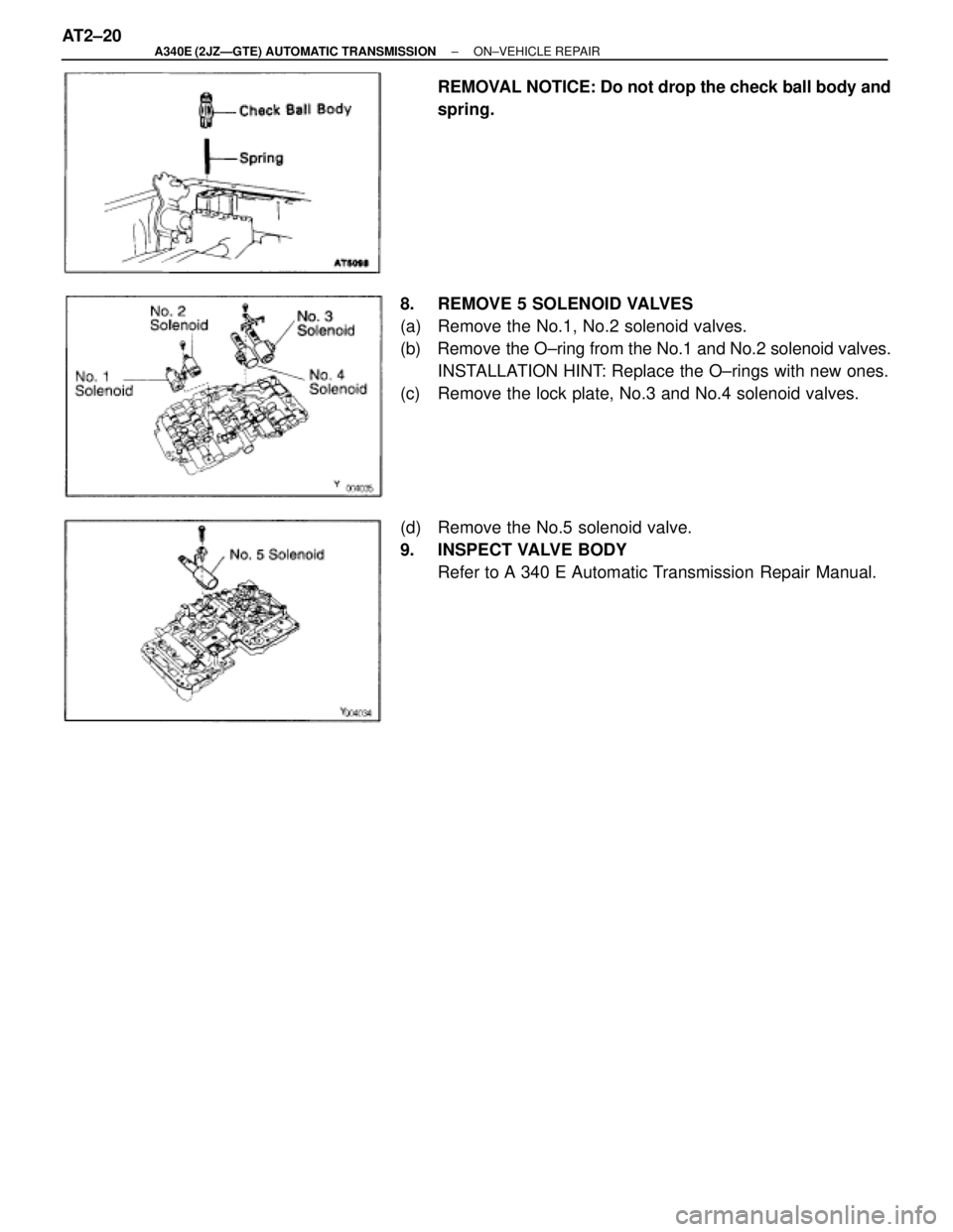
REMOVAL NOTICE: Do not drop the check ball body and
spring.
8. REMOVE 5 SOLENOID VALVES
(a) Remove the No.1, No.2 solenoid valves.
(b) Remove the O±ring from the No.1 and No.2 solenoid valves.
INSTALLATION HINT: Replace the O±rings with new ones.
(c) Remove the lock plate, No.3 and No.4 solenoid valves.
(d) Remove the No.5 solenoid valve.
9. INSPECT VALVE BODY
Refer to A 340 E Automatic Transmission Repair Manual. AT2±20
± A340E (2JZÐGTE) AUTOMATIC TRANSMISSIONON±VEHICLE REPAIR
Page 505 of 2543
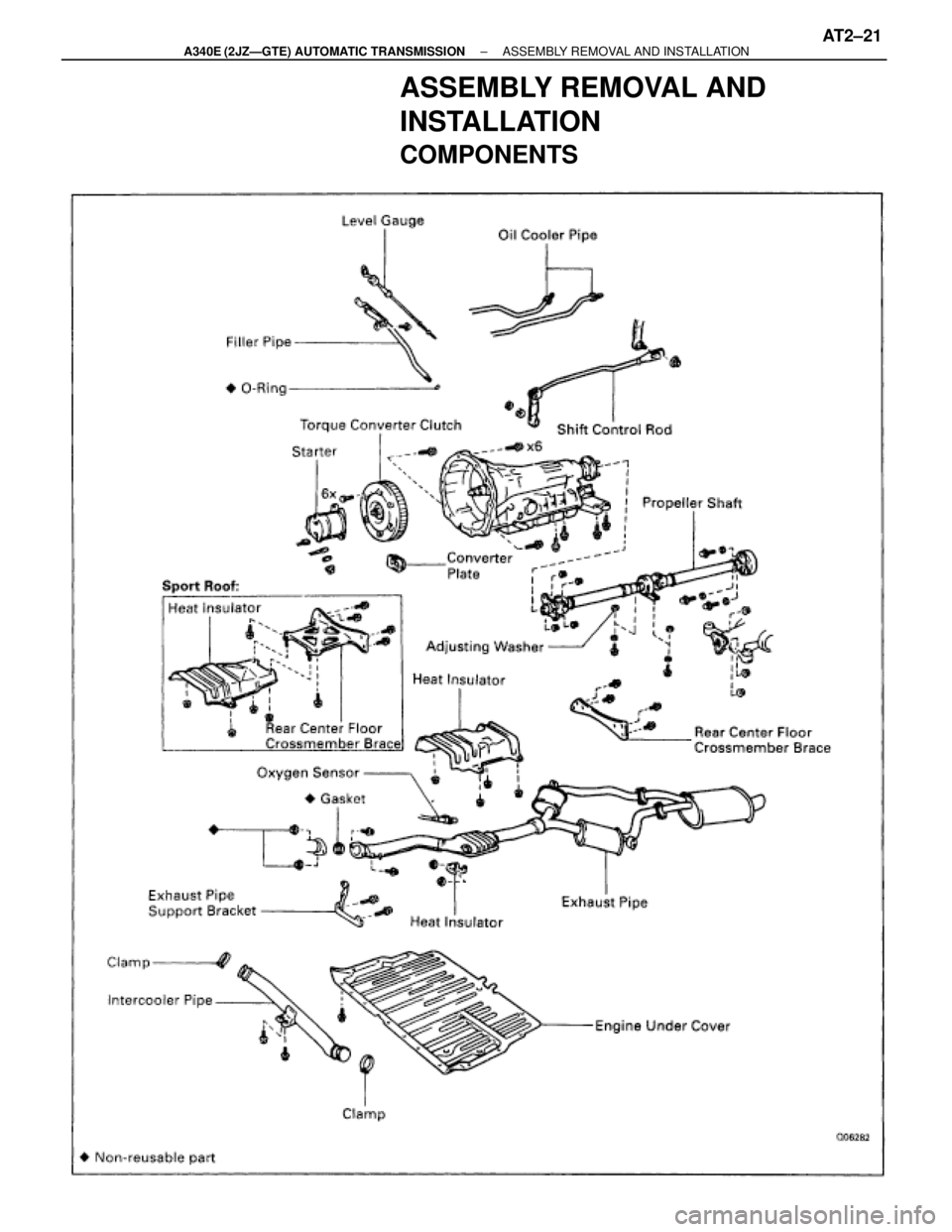
ASSEMBLY REMOVAL AND
INSTALLATION
COMPONENTS
± A340E (2JZÐGTE) AUTOMATIC TRANSMISSIONASSEMBLY REMOVAL AND INSTALLATIONAT2±21
Page 506 of 2543
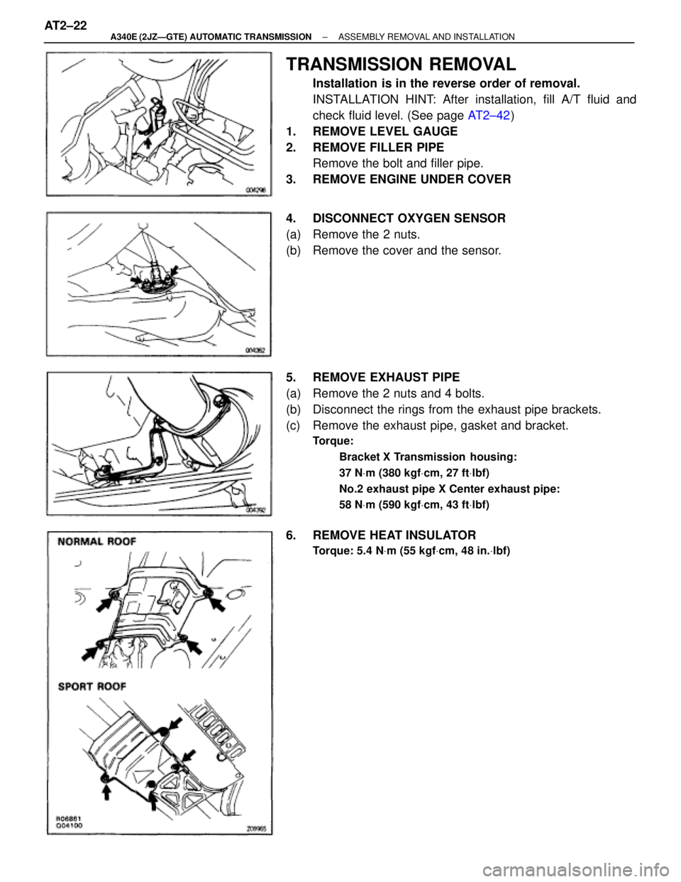
TRANSMISSION REMOVAL
Installation is in the reverse order of removal.
INSTALLATION HINT: After installation, fill A/T fluid and
check fluid level. (See page AT2±42)
1. REMOVE LEVEL GAUGE
2. REMOVE FILLER PIPE
Remove the bolt and filler pipe.
3. REMOVE ENGINE UNDER COVER
4. DISCONNECT OXYGEN SENSOR
(a) Remove the 2 nuts.
(b) Remove the cover and the sensor.
5. REMOVE EXHAUST PIPE
(a) Remove the 2 nuts and 4 bolts.
(b) Disconnect the rings from the exhaust pipe brackets.
(c) Remove the exhaust pipe, gasket and bracket.
Torque:
Bracket X Transmission housing:
37 NVm (380 kgfVcm, 27 ftVlbf)
No.2 exhaust pipe X Center exhaust pipe:
58 NVm (590 kgfVcm, 43 ftVlbf)
6. REMOVE HEAT INSULATOR
Torque: 5.4 NVm (55 kgfVcm, 48 in.Vlbf)
AT2±22± A340E (2JZÐGTE) AUTOMATIC TRANSMISSIONASSEMBLY REMOVAL AND INSTALLATION
Page 507 of 2543
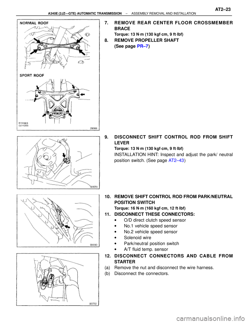
7. REMOVE REAR CENTER FLOOR CROSSMEMBER
BRACE
Torque: 13 NVm (130 kgfVcm, 9 ftVlbf)
8. REMOVE PROPELLER SHAFT
(See page PR±7)
9. DISCONNECT SHIFT CONTROL ROD FROM SHIFT
LEVER
Torque: 13 NVm (130 kgfVcm, 9 ftVlbf)
INSTALLATION HINT: Inspect and adjust the park/ neutral
position switch. (See page AT2±43)
10. REMOVE SHIFT CONTROL ROD FROM PARK/NEUTRAL
POSITION SWITCH
Torque: 16 NVm (160 kgfVcm, 12 ftVlbf)
11. DISCONNECT THESE CONNECTORS:
wO/D direct clutch speed sensor
wNo.1 vehicle speed sensor
wNo.2 vehicle speed sensor
wSolenoid wire
wPark/neutral position switch
wA/T fluid temp. sensor
12. D I S C O N N E C T C O N N E C TO R S A N D C A B L E F R O M
STARTER
(a) Remove the nut and disconnect the wire harness.
(b) Disconnect the connectors.
± A340E (2JZÐGTE) AUTOMATIC TRANSMISSIONASSEMBLY REMOVAL AND INSTALLATIONAT2±23
Page 508 of 2543
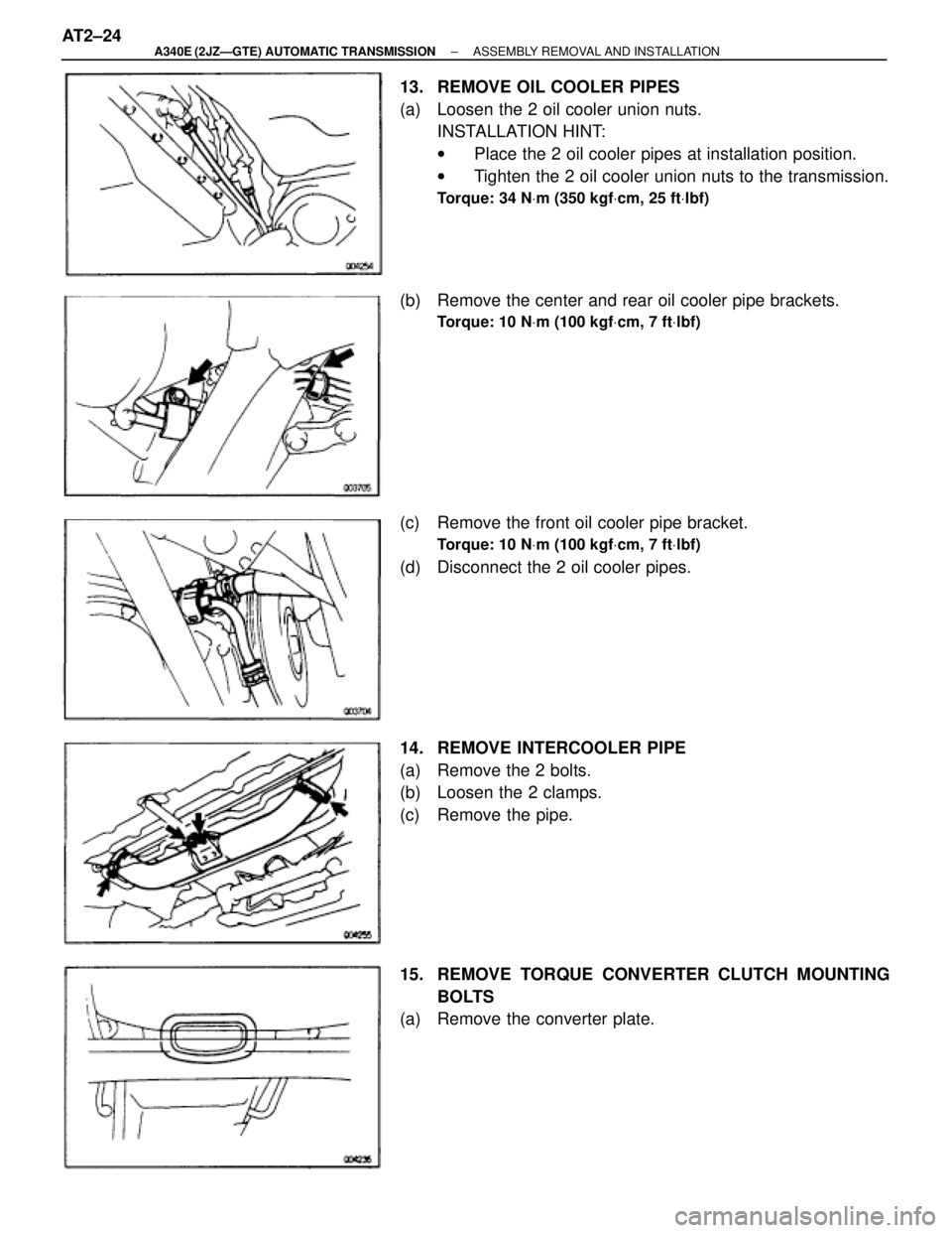
13. REMOVE OIL COOLER PIPES
(a) Loosen the 2 oil cooler union nuts.
INSTALLATION HINT:
wPlace the 2 oil cooler pipes at installation position.
wTighten the 2 oil cooler union nuts to the transmission.
Torque: 34 NVm (350 kgfVcm, 25 ftVlbf)
(b) Remove the center and rear oil cooler pipe brackets.
Torque: 10 NVm (100 kgfVcm, 7 ftVlbf)
(c) Remove the front oil cooler pipe bracket.
Torque: 10 NVm (100 kgfVcm, 7 ftVlbf)
(d) Disconnect the 2 oil cooler pipes.
14. REMOVE INTERCOOLER PIPE
(a) Remove the 2 bolts.
(b) Loosen the 2 clamps.
(c) Remove the pipe.
15. REMOVE TORQUE CONVERTER CLUTCH MOUNTING
BOLTS
(a) Remove the converter plate. AT2±24
± A340E (2JZÐGTE) AUTOMATIC TRANSMISSIONASSEMBLY REMOVAL AND INSTALLATION
Page 509 of 2543
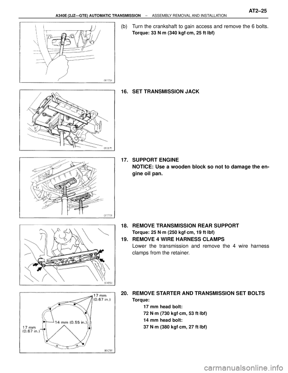
(b) Turn the crankshaft to gain access and remove the 6 bolts.
Torque: 33 NVm (340 kgfVcm, 25 ftVlbf)
16. SET TRANSMISSION JACK
17. SUPPORT ENGINE
NOTICE: Use a wooden block so not to damage the en-
gine oil pan.
18. REMOVE TRANSMISSION REAR SUPPORT
Torque: 25 NVm (250 kgfVcm, 19 ftVlbf)
19. REMOVE 4 WIRE HARNESS CLAMPS
Lower the transmission and remove the 4 wire harness
clamps from the retainer.
20. REMOVE STARTER AND TRANSMISSION SET BOLTS
Torque:
17 mm head bolt:
72 NVm (730 kgfVcm, 53 ftVlbf)
14 mm head bolt:
37 NVm (380 kgfVcm, 27 ftVlbf)
± A340E (2JZÐGTE) AUTOMATIC TRANSMISSIONASSEMBLY REMOVAL AND INSTALLATIONAT2±25
Page 510 of 2543
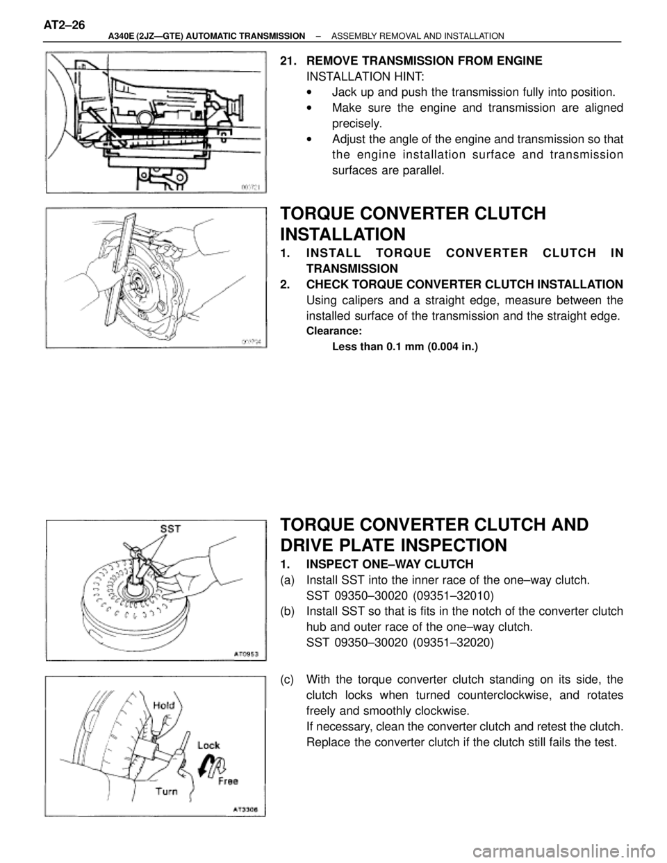
21. REMOVE TRANSMISSION FROM ENGINE
INSTALLATION HINT:
wJack up and push the transmission fully into position.
wMake sure the engine and transmission are aligned
precisely.
wAdjust the angle of the engine and transmission so that
the engine installation surface and transmission
surfaces are parallel.
TORQUE CONVERTER CLUTCH
INSTALLATION
1. INSTALL TORQUE CONVERTER CLUTCH IN
TRANSMISSION
2. CHECK TORQUE CONVERTER CLUTCH INSTALLATION
Using calipers and a straight edge, measure between the
installed surface of the transmission and the straight edge.
Clearance:
Less than 0.1 mm (0.004 in.)
TORQUE CONVERTER CLUTCH AND
DRIVE PLATE INSPECTION
1. INSPECT ONE±WAY CLUTCH
(a) Install SST into the inner race of the one±way clutch.
SST 09350±30020 (09351±32010)
(b) Install SST so that is fits in the notch of the converter clutch
hub and outer race of the one±way clutch.
SST 09350±30020 (09351±32020)
(c) With the torque converter clutch standing on its side, the
clutch locks when turned counterclockwise, and rotates
freely and smoothly clockwise.
If necessary, clean the converter clutch and retest the clutch.
Replace the converter clutch if the clutch still fails the test. AT2±26
± A340E (2JZÐGTE) AUTOMATIC TRANSMISSIONASSEMBLY REMOVAL AND INSTALLATION