TOYOTA SUPRA 1997 Service Repair Manual
SUPRA 1997
TOYOTA
TOYOTA
https://www.carmanualsonline.info/img/14/57469/w960_57469-0.png
TOYOTA SUPRA 1997 Service Repair Manual
Trending: oil viscosity, ignition, alternator, open hood, ABS, audio, key battery
Page 411 of 1807
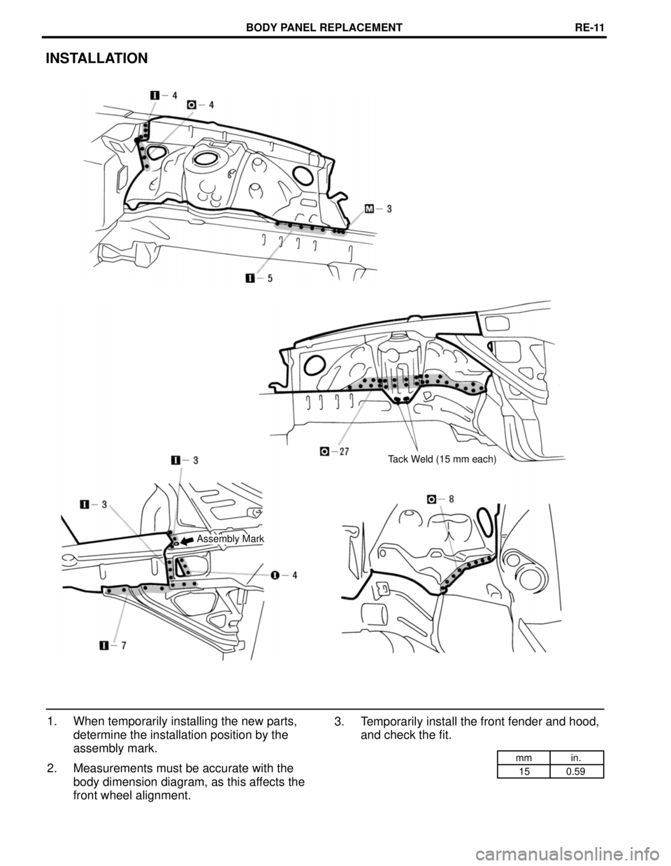
mm in.
15 0.59 Assembly Mark
INSTALLATION
Tack Weld (15 mm each)
3. Temporarily install the front fender and hood,
and check the fit. 1. When temporarily installing the new parts,
determine the installation position by the
assembly mark.
2. Measurements must be accurate with the
body dimension diagram, as this affects the
front wheel alignment.
BODY PANEL REPLACEMENTRE-11
Page 412 of 1807
Page 413 of 1807
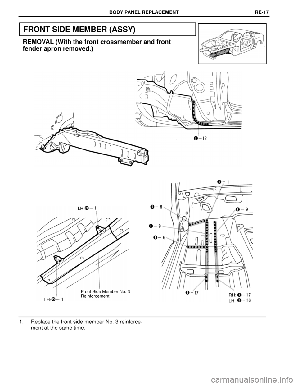
FRONT SIDE MEMBER (ASSY)
REMOVAL (With the front crossmember and front
fender apron removed.)
LH:
Front Side Member No. 3
Reinforcement
LH:RH:
LH:
1. Replace the front side member No. 3 reinforce-
ment at the same time.
BODY PANEL REPLACEMENTRE-17
Page 414 of 1807
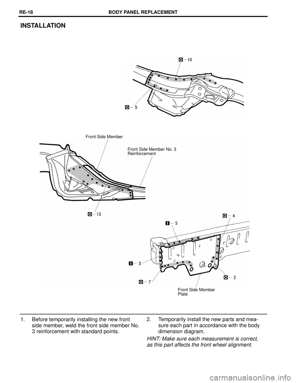
INSTALLATION
Front Side Member
Front Side Member No. 3
Reinforcement
Front Side Member
Plate
2. Temporarily install the new parts and mea-
sure each part in accordance with the body
dimension diagram.
HINT: Make sure each measurement is correct,
as this part affects the front wheel alignment.
1. Before temporarily installing the new front
side member, weld the front side member No.
3 reinforcement with standard points.
BODY PANEL REPLACEMENTRE-18
Page 415 of 1807
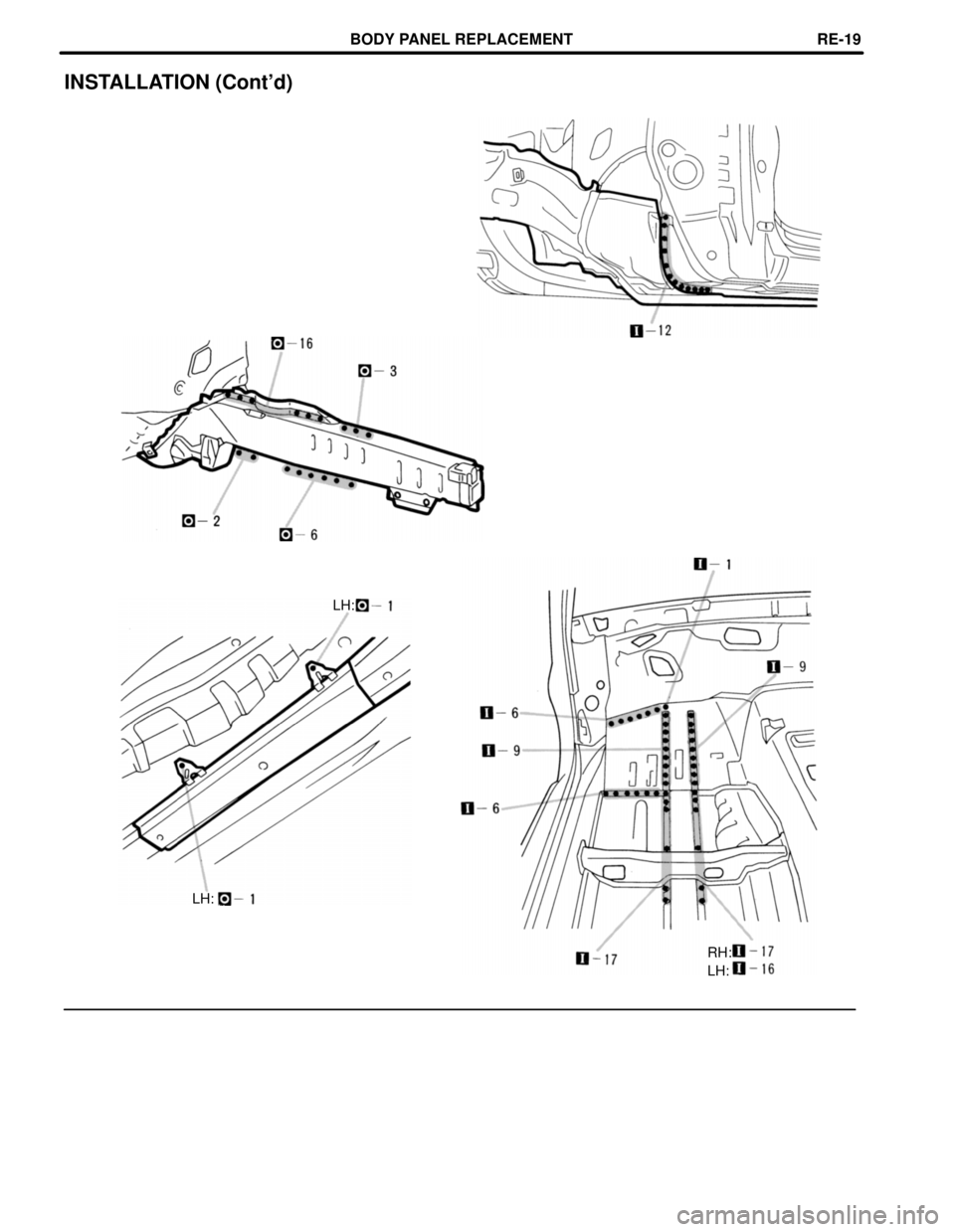
INSTALLATION (Cont'd)
LH:
LH:
RH:
LH:
BODY PANEL REPLACEMENTRE-19
Page 416 of 1807
mm in.
30
40
100
1501.18
1.57
3.94
5.91
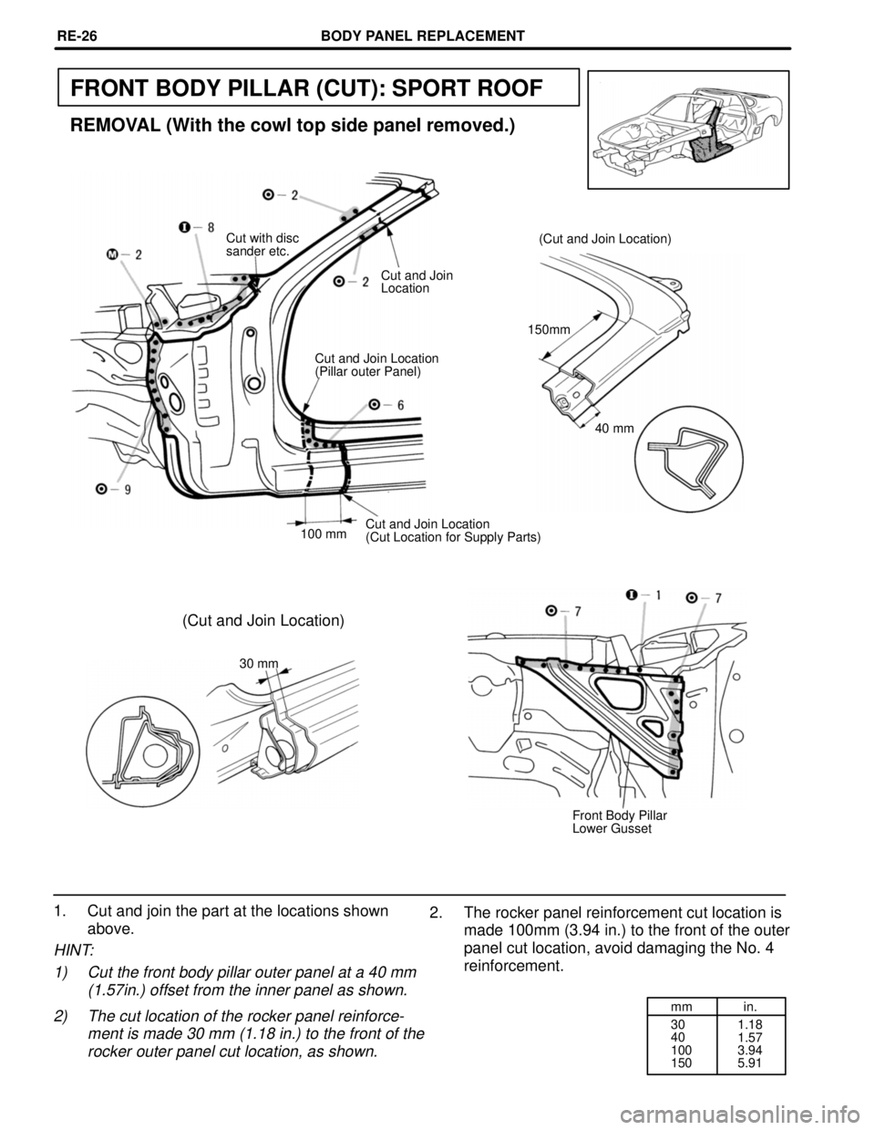
FRONT BODY PILLAR (CUT): SPORT ROOF
REMOVAL (With the cowl top side panel removed.)
(Cut and Join Location) Cut with disc
sander etc.
Cut and Join
Location
150mm
Cut and Join Location
(Pillar outer Panel)
40 mm
100 mmCut and Join Location
(Cut Location for Supply Parts)
(Cut and Join Location)
30 mm
Front Body Pillar
Lower Gusset
1. Cut and join the part at the locations shown
above.
HINT:
1) Cut the front body pillar outer panel at a 40 mm
(1.57in.) offset from the inner panel as shown.
2) The cut location of the rocker panel reinforce-
ment is made 30 mm (1.18 in.) to the front of the
rocker outer panel cut location, as shown.
2. The rocker panel reinforcement cut location is
made 100mm (3.94 in.) to the front of the outer
panel cut location, avoid damaging the No. 4
reinforcement.
BODY PANEL REPLACEMENTRE-26
Page 417 of 1807
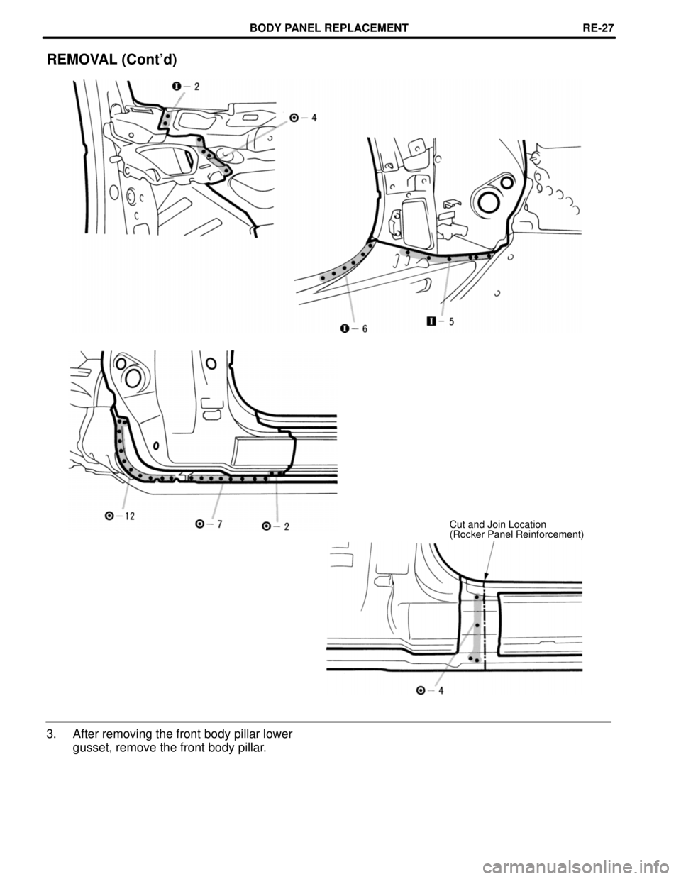
REMOVAL (Cont'd)
Cut and Join Location
(Rocker Panel Reinforcement)
3. After removing the front body pillar lower
gusset, remove the front body pillar.
BODY PANEL REPLACEMENTRE-27
Page 418 of 1807
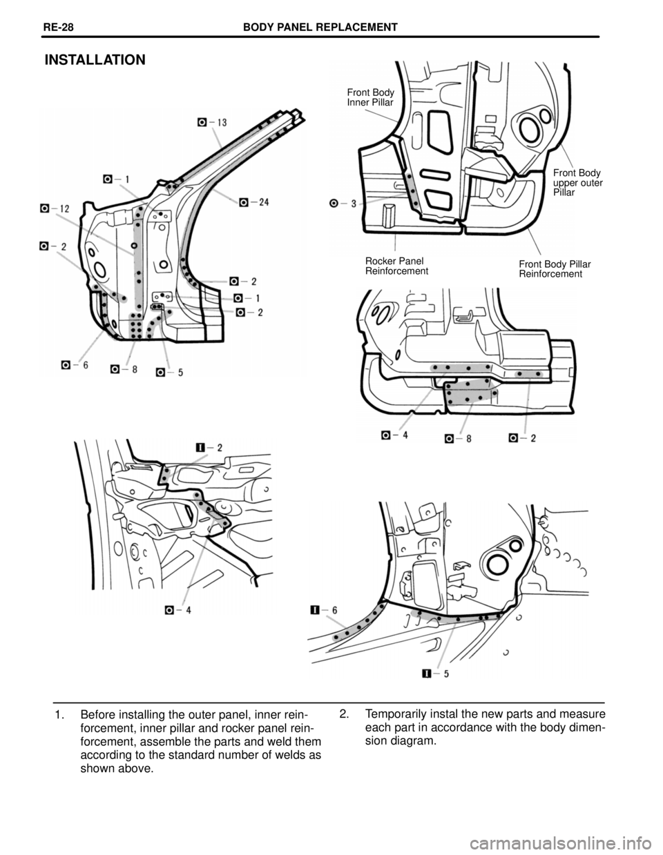
1. Before installing the outer panel, inner rein-
forcement, inner pillar and rocker panel rein-
forcement, assemble the parts and weld them
according to the standard number of welds as
shown above.
INSTALLATION
Front Body
Inner Pillar
Front Body
upper outer
Pillar
Rocker Panel
ReinforcementFront Body Pillar
Reinforcement
2. Temporarily instal the new parts and measure
each part in accordance with the body dimen-
sion diagram.
BODY PANEL REPLACEMENTRE-28
Page 419 of 1807
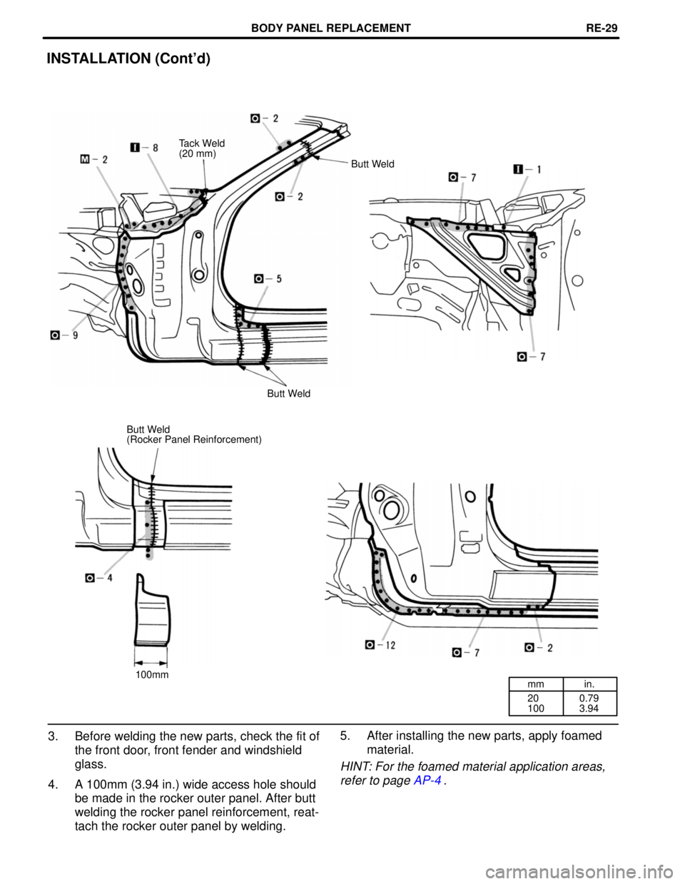
mm in.
20
1000.79
3.94
3. Before welding the new parts, check the fit of
the front door, front fender and windshield
glass.
4. A 100mm (3.94 in.) wide access hole should
be made in the rocker outer panel. After butt
welding the rocker panel reinforcement, reat-
tach the rocker outer panel by welding.
INSTALLATION (Cont'd)
Tack Weld
(20 mm)
Butt Weld
Butt Weld
Butt Weld
(Rocker Panel Reinforcement)
100mm
5. After installing the new parts, apply foamed
material.
HINT: For the foamed material application areas,
refer to page AP-4.
BODY PANEL REPLACEMENTRE-29
Page 420 of 1807
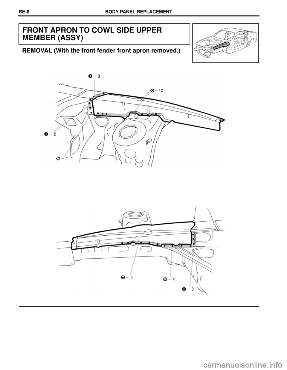
FRONT APRON TO COWL SIDE UPPER
MEMBER (ASSY)
REMOVAL (With the front fender front apron removed.)
BODY PANEL REPLACEMENTRE-8
Trending: air conditioner, buttons, brake pads replacement, dimensions, fuel tank capacity, interior, clock reset
