tow TOYOTA SUPRA 2023 Owner's Manual
[x] Cancel search | Manufacturer: TOYOTA, Model Year: 2023, Model line: SUPRA, Model: TOYOTA SUPRA 2023Pages: 372, PDF Size: 6.32 MB
Page 262 of 372
2624-1. DRIVING TIPS
perforated brake discs can emit
functional noises. However,
functional noises have no effect
on the performance and opera-
tional reliability of the brake.
When roads are wet, salted, or
in heavy rain, gently press the
brake pedal every few miles.
Ensure that this action does not
endanger other traffic.
The heat generated during brak-
ing dries brake discs and brake
pads and protects them against
corrosion.
In this way braking efficiency will
be available when you need it.
■General information
Drive long or steep downhill gra-
dients in the gear that requires
least braking effort. Otherwise,
the brakes may overheat and
reduce brake efficiency.
You can increase the engine's
braking effect by shifting down,
going all the way to first gear, if
needed.
■Safety information
Corrosion on the brake discs
and contamination on the brake
pads are increased by the fol-
lowing circumstances:
Low mileage.
Extended periods when the
vehicle is not used at all.
Objects in the area around
the pedals
WARNING
Objects in the dri
ver's floor area
can limit the peda l distance or
block a depressed pedal. There is
a risk of an accident. Stow objects
in the vehicle such that they are
secured and cannot enter into the
driver's floor area. Use floor mats
that are suitable for the vehicle
and can be safely attached to the
floor. Do not use loose floor mats
and do not layer several floor
mats. Make sure that there is suf-
ficient clearance for the pedals.
Ensure that the floor mats are
securely fastened again after they
were removed, fo r instance for
cleaning.
Driving in wet conditions
Hills
WARNING
Light but consis tent brake pres-
sure can lead to high tempera-
tures, brakes wearing out and
possibly even brake failure. There
is a risk of an accident. Avoid
placing excessive stress on the
brake system.
WARNING
In idle state or with the engine
switched off, safety functions, for
instance engine braking effect,
braking assistance and steering
assistance, may not be available.
There is a risk of accident. Do not
attempt to drive in idle state or
with the engine switched off.
Brake disc corrosion
Page 279 of 372
2795-1. MOBILITY
5
MOBILITY
occur with low-profile tires,
which provide less cushioning
between the wheel and the
road. Be careful to avoid road
hazards and reduce your speed,
especially if your vehicle is
equipped with low-profile tires.
Indications of tire damage or
other vehicle malfunctions:
• Unusual vibrations.
• Unusual tire or running noises.
• Unusual handling such as a strong tendency to pull to the
left or right.
• Uneven wear pattern, e.g., increased wear in the area of
the tire shoulder.
Damage can be caused by the
following situations, for instance:
• Driving over curbs.
• Road damage.
• Tire inflation pressure too low.
• Vehicle overloading.
• Incorrect tire storage. Have mounting and wheel bal-
ancing carried out by your Toy-
ota dealer.
The following properties are rec-
ommended and approved by the
manufacturer of the vehicle for
the approved wheels and tires
per vehicle type and special
equipment:
• Wheel and tire combinations.
• Rim designs.
• Tire sizes.
• Tire brands.
You can ask your Toyota dealer
about the approved wheels and
tires for the vehicle and the spe-
cial equipment.
Safety information
WARNING
Damaged tires can lose tire infla-
tion pressure, which can lead to
loss of vehicle control. There is a
risk of an accident. If tire damage
is suspected while driving, imme-
diately reduce speed and stop.
Have wheels and tires checked.
For this purpose, drive carefully to
the nearest your Toyota dealer.
Have vehicle towed or trans-
ported as needed. Do not repair
damaged tires, but have them
replaced.
WARNING
Tires can become damaged by
driving over obstacles, e.g., curbs
or road damage, at high speed.
Larger wheels have a smaller tire
crosssection. The smaller the tire
cross-section, the
higher the risk
of tire damage. There is a danger
of accidents and property dam-
age. If possible, avoid driving over
objects or road conditions that
may damage tires, or drive over
them slowly and carefully.
Changing wheels and
tires
Mounting and wheel bal-
ancing
Approved wheels and tires
General information
Page 285 of 372
2855-1. MOBILITY
5
MOBILITY
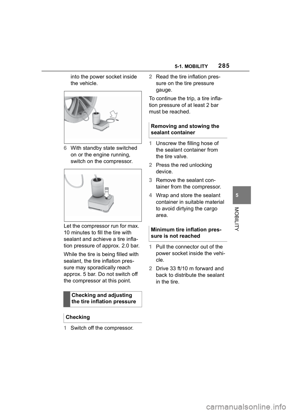
into the power socket inside
the vehicle.
6 With standby state switched
on or the engine running,
switch on the compressor.
Let the compressor run for max.
10 minutes to fill the tire with
sealant and achieve a tire infla-
tion pressure of approx. 2.0 bar.
While the tire is being filled with
sealant, the tire inflation pres-
sure may sporadically reach
approx. 5 bar. Do not switch off
the compressor at this point.
1 Switch off the compressor. 2
Read the tire inflation pres-
sure on the tire pressure
gauge.
To continue the trip, a tire infla-
tion pressure of at least 2 bar
must be reached.
1 Unscrew the filling hose of
the sealant container from
the tire valve.
2 Press the red unlocking
device.
3 Remove the sealant con-
tainer from the compressor.
4 Wrap and store the sealant
container in suitable material
to avoid dirtying the cargo
area.
1 Pull the connector out of the
power socket inside the vehi-
cle.
2 Drive 33 ft/10 m forward and
back to distribute the sealant
in the tire.
Checking and adjusting
the tire inflation pressure
Checking
Removing and stowing the
sealant container
Minimum tire inflation pres-
sure is not reached
Page 286 of 372
2865-1. MOBILITY
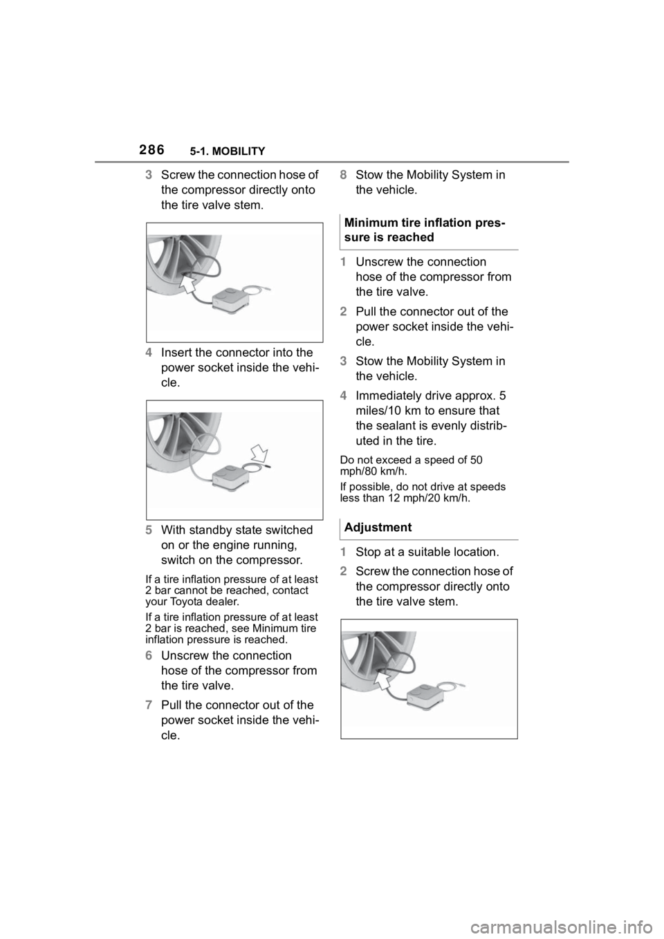
3Screw the connection hose of
the compressor directly onto
the tire valve stem.
4 Insert the connector into the
power socket inside the vehi-
cle.
5 With standby state switched
on or the engine running,
switch on the compressor.
If a tire inflation pressure of at least
2 bar cannot be reached, contact
your Toyota dealer.
If a tire inflation pressure of at least
2 bar is reached, see Minimum tire
inflation pressure is reached.
6Unscrew the connection
hose of the compressor from
the tire valve.
7 Pull the connector out of the
power socket inside the vehi-
cle. 8
Stow the Mobility System in
the vehicle.
1 Unscrew the connection
hose of the compressor from
the tire valve.
2 Pull the connector out of the
power socket inside the vehi-
cle.
3 Stow the Mobility System in
the vehicle.
4 Immediately drive approx. 5
miles/10 km to ensure that
the sealant is evenly distrib-
uted in the tire.
Do not exceed a speed of 50
mph/80 km/h.
If possible, do no t drive at speeds
less than 12 mph/20 km/h.
1 Stop at a suitable location.
2 Screw the connection hose of
the compressor directly onto
the tire valve stem.
Minimum tire inflation pres-
sure is reached
Adjustment
Page 287 of 372
2875-1. MOBILITY
5
MOBILITY
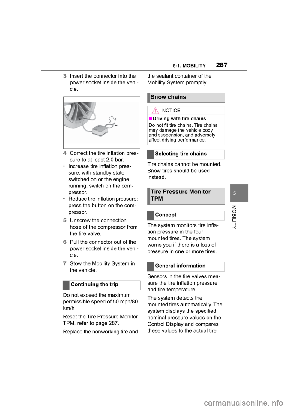
3Insert the connector into the
power socket inside the vehi-
cle.
4 Correct the tire inflation pres-
sure to at least 2.0 bar.
• Increase tire inflation pres- sure: with standby state
switched on or the engine
running, switch on the com-
pressor.
• Reduce tire inflation pressure: press the button on the com-
pressor.
5 Unscrew the connection
hose of the compressor from
the tire valve.
6 Pull the connector out of the
power socket inside the vehi-
cle.
7 Stow the Mobility System in
the vehicle.
Do not exceed the maximum
permissible speed of 50 mph/80
km/h
Reset the Tire Pressure Monitor
TPM, refer to page 287.
Replace the nonworking tire and the sealant container of the
Mobility System promptly.
Tire chains cannot be mounted.
Snow tires should be used
instead.
The system monitors tire infla-
tion pressure in the four
mounted tires. The system
warns you if there is a loss of
pressure in one or more tires.
Sensors in the tire valves mea-
sure the tire inflation pressure
and tire temperature.
The system detects the
mounted tires automatically. The
system displays the specified
nominal pressure values on the
Control Display and compares
these values to the actual tire
Continuing the trip
Snow chains
NOTICE
■Driving with tire chains
Do not fit tire chains. Tire chains
may damage the vehicle body
and suspension, and adversely
affect driving performance.
Selecting tire chains
Tire Pressure Monitor
TPM
Concept
General information
Page 297 of 372
2975-1. MOBILITY
5
MOBILITY
3Remove the adapter and
stow it after screwing on the
lug bolt.
This chapter describes all stan-
dard, country-specific and
optional features offered with
the series. It also describes fea-
tures and functions that are not
necessarily available in your
vehicle, e.g., due to the selected
options or country versions. This
also applies to safety-related
functions and systems. When
using these functions and sys-
tems, the applicable laws and
regulations must be observed.Engine compar tment
Vehicle features and
options
Page 326 of 372
3265-1. MOBILITY
2Attach one terminal clamp of
the positive jumper cable to
the positive terminal of the
battery, or to the correspond-
ing starting aid terminal of the
vehicle providing assistance.
3 Attach the terminal clamp on
the other end of the cable to
the positive terminal of the
battery, or to the correspond-
ing starting aid terminal of the
vehicle to be started.
4 Attach one terminal clamp of
the negative jumper cable to
the negative terminal of the
battery, or to the correspond-
ing engine or body ground of
assisting vehicle.
5 Attach the second terminal
clamp to the negative termi-
nal of the battery, or to the
corresponding engine or
body ground of the vehicle to
be started.
Never use spray fluids to start
the engine.
1 Start the engine of the assist-
ing vehicle and let it run for
several minutes at an
increased idle speed.
2 Start the engine of the vehicle
that is to be started in the
usual way.
If the first starting attempt is not
successful, wait a few minutes
before making another attempt in order to allow the discharged bat-
tery to recharge.
3
Let both engines run for sev-
eral minutes.
4 Disconnect the jumper
cables in the reverse order.
Check the battery and recharge,
if needed.
Starting the engine
Tow-starting and towing
Safety information
WARNING
Due to system limits, individual
functions can malfunction during
tow-starting/towing with the Toy-
ota Supra Safety systems acti-
vated. There is a risk of an
accident. Switch all Toyota Supra
Safety systems off prior to
tow-starting/towing.
Manual transmission
Safety information
NOTICE
The vehicle can become dam-
aged when lifting and securing it.
There is a risk of damage to prop-
erty.
●Lift the vehicle using suitable
means.
●Do not lift or secure the vehicle
by its tow fitting, body parts, or
suspension parts.
Page 327 of 372
3275-1. MOBILITY
5
MOBILITY
A broken-down vehicle can be
towed or pushed.
Follow the following instructions:
Make sure that the standby
state isswitched on; other-
wise, the low beams, tail
lights, turn signals, and wipers
may be unavailable.
Do not tow the vehicle with
the rear axle tilted, as the
front wheels could turn.
When the engine is stopped,
there is no power assistance.
Consequently, more effort
needs to be applied when
braking and steering.
Larger steering wheel move-
ments are required.
The towing vehicle must not
be lighter than the vehicle
being towed; otherwise, it will
not be possible to control han-
dling.
Do not exceed a towing
speed of 30 mph/50 km/h.
Do not exceed a towing dis-
tance of 30 miles/50 km.
Additional information:
Rolling or pushing the vehicle,
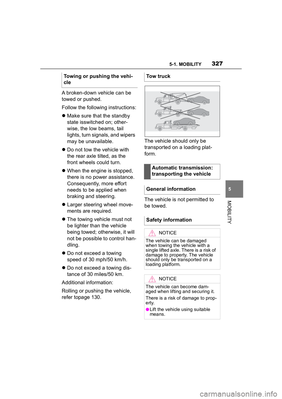
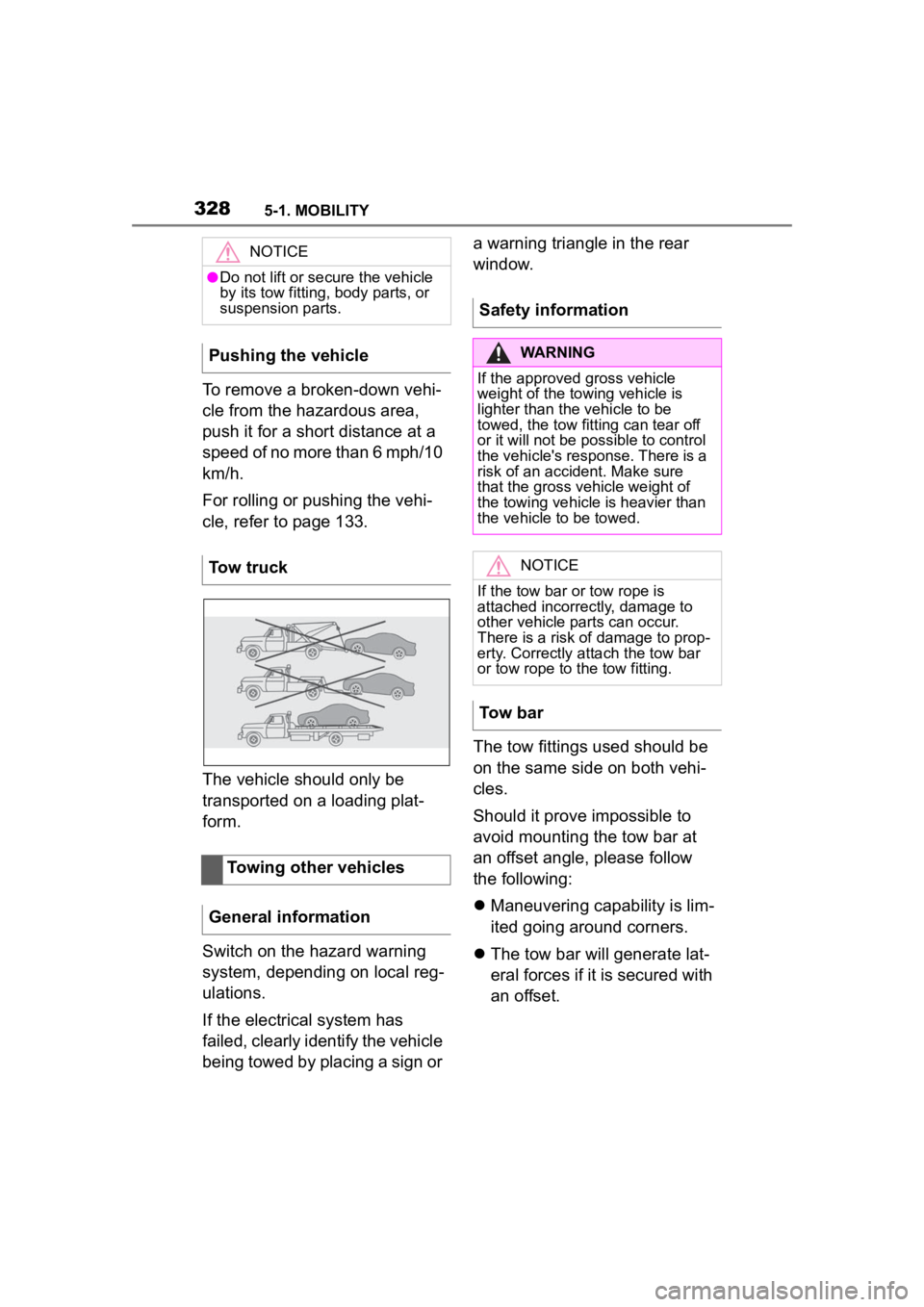
refer topage 130. The vehicle should only be
transported on a loading plat-
form.
The vehicle is not permitted to
be towed.
Towing or pushing the vehi-
cle
Tow truck
Automatic transmission:
transporting the vehicle
General information
Safety information
NOTICE
The vehicle can be damaged
when towing the vehicle with a
single lifted axle. There is a risk of
damage to property. The vehicle
should only be transported on a
loading platform.
NOTICE
The vehicle can become dam-
aged when lifting and securing it.
There is a risk of damage to prop-
erty.
●Lift the vehicle using suitable
means.
Page 328 of 372
3285-1. MOBILITY
To remove a broken-down vehi-
cle from the hazardous area,
push it for a short distance at a
speed of no more than 6 mph/10
km/h.
For rolling or pushing the vehi-
cle, refer to page 133.
The vehicle should only be
transported on a loading plat-
form.
Switch on the hazard warning
system, depending on local reg-
ulations.
If the electrical system has
failed, clearly identify the vehicle
being towed by placing a sign or a warning triangle in the rear
window.
The tow fittings used should be
on the same side on both vehi-
cles.
Should it prove impossible to
avoid mounting the tow bar at
an offset angle, please follow
the following:
Maneuvering capability is lim-
ited going around corners.
The tow bar will generate lat-
eral forces if it is secured with
an offset.
NOTICE
●Do not lift or se cure the vehicle
by its tow fitting, body parts, or
suspension parts.
Pushing the vehicle
Tow truck
Towing other vehicles
General information
Safety information
WARNING
If the approved gross vehicle
weight of the towing vehicle is
lighter than the vehicle to be
towed, the tow fitting can tear off
or it will not be possible to control
the vehicle's response. There is a
risk of an accident. Make sure
that the gross v ehicle weight of
the towing vehicle is heavier than
the vehicle to be towed.
NOTICE
If the tow bar or tow rope is
attached incorrectly, damage to
other vehicle pa rts can occur.
There is a risk of damage to prop-
erty. Correctly a ttach the tow bar
or tow rope to the tow fitting.
Tow bar
Page 329 of 372
3295-1. MOBILITY
5
MOBILITY
Observe the following notes
when using the tow rope:
Use nylon ropes or straps,
which will enable the vehicle
to be towed without jerking.
Make sure the tow rope is not
twisted when fastening.
Check the fastening of the
tow fitting and tow rope in reg-
ular intervals.
Do not exceed a towing
speed of 30 mph/50 km/h.
Do not exceed a towing dis-
tance of 3 miles/5 km.
When starting to tow the vehi-
cle, make sure that the tow
rope is taut.
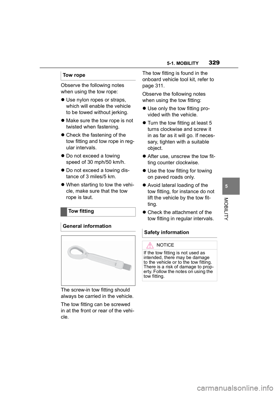
The screw-in tow fitting should
always be carried in the vehicle.
The tow fitting can be screwed
in at the front or rear of the vehi-
cle. The tow fitting is found in the
onboard vehicle tool kit, refer to
page 311.
Observe the following notes
when using the tow fitting:
Use only the tow fitting pro-
vided with the vehicle.
Turn the tow fitting at least 5
turns clockwise and screw it
in as far as it will go. If neces-
sary, tighten with a suitable
object.
After use, unscrew the tow fit-
ting counter clockwise.
Use the tow fitting for towing
on paved roads only.
Avoid lateral loading of the
tow fitting, for instance do not
lift the vehicle by the tow fit-
ting.
Check the attachment of the
tow fitting in regular intervals.
Tow rope
Tow fitting
General information
Safety information
NOTICE
If the tow fitting is not used as
intended, there may be damage
to the vehicle or to the tow fitting.
There is a risk of damage to prop-
erty. Follow the notes on using the
tow fitting.