light TOYOTA SUPRA 2023 Service Manual
[x] Cancel search | Manufacturer: TOYOTA, Model Year: 2023, Model line: SUPRA, Model: TOYOTA SUPRA 2023Pages: 372, PDF Size: 6.32 MB
Page 140 of 372
1403-1. CONTROLS
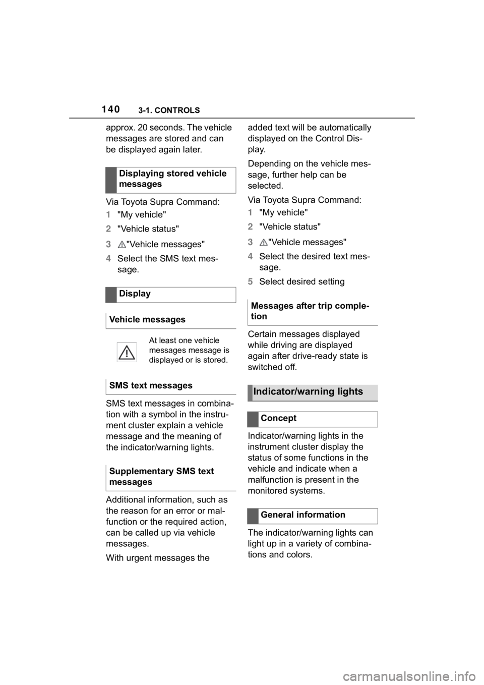
approx. 20 seconds. The vehicle
messages are stored and can
be displayed again later.
Via Toyota Supra Command:
1"My vehicle"
2 "Vehicle status"
3 "Vehicle messages"
4 Select the SMS text mes-
sage.
SMS text messages in combina-
tion with a symbol in the instru-
ment cluster explain a vehicle
message and the meaning of
the indicator/warning lights.
Additional information, such as
the reason for an error or mal-
function or the required action,
can be called up via vehicle
messages.
With urgent messages the added text will be automatically
displayed on the Control Dis-
play.
Depending on the vehicle mes-
sage, further help can be
selected.
Via Toyota Supra Command:
1
"My vehicle"
2 "Vehicle status"
3 "Vehicle messages"
4 Select the desired text mes-
sage.
5 Select desired setting
Certain messages displayed
while driving are displayed
again after drive-ready state is
switched off.
Indicator/warning lights in the
instrument cluster display the
status of some functions in the
vehicle and indicate when a
malfunction is present in the
monitored systems.
The indicator/warning lights can
light up in a variety of combina-
tions and colors.
Displaying stored vehicle
messages
Display
Vehicle messages
At least one vehicle
messages message is
displayed or is stored.
SMS text messages
Supplementary SMS text
messages
Messages after trip comple-
tion
Indicator/warning lights
Concept
General information
Page 141 of 372
1413-1. CONTROLS
3
CONTROLS
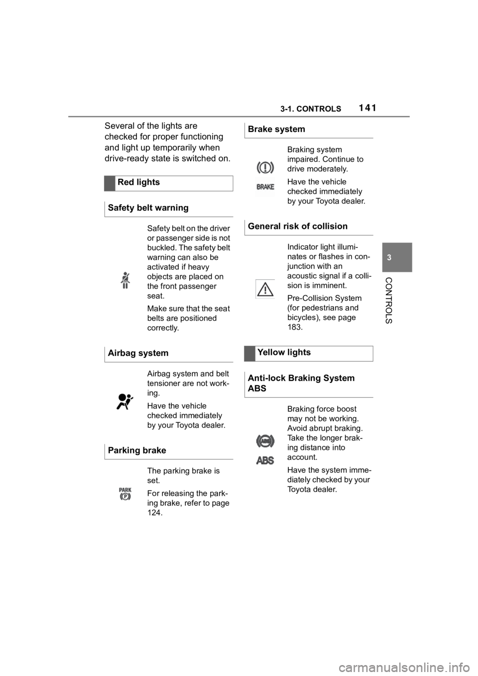
Several of the lights are
checked for proper functioning
and light up temporarily when
drive-ready state is switched on.Red lights
Safety belt warning
Safety belt on the driver
or passenger side is not
buckled. The safety belt
warning can also be
activated if heavy
objects are placed on
the front passenger
seat.
Make sure that the seat
belts are positioned
correctly.
Airbag system
Airbag system and belt
tensioner are not work-
ing.
Have the vehicle
checked immediately
by your Toyota dealer.
Parking brake
The parking brake is
set.
For releasing the park-
ing brake, refer to page
124.
Brake system
Braking system
impaired. Continue to
drive moderately.
Have the vehicle
checked immediately
by your Toyota dealer.
General risk of collision
Indicator light illumi-
nates or flashes in con-
junction with an
acoustic signal if a colli-
sion is imminent.
Pre-Collision System
(for pedestrians and
bicycles), see page
183.
Yellow lights
Anti-lock Braking System
ABS
Braking force boost
may not be working.
Avoid abrupt braking.
Take the longer brak-
ing distance into
account.
Have the system imme-
diately checked by your
Toyota dealer.
Page 142 of 372
1423-1. CONTROLS
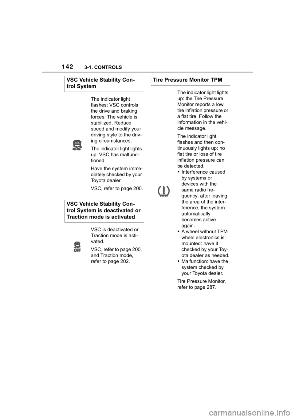
VSC Vehicle Stability Con-
trol System
The indicator light
flashes: VSC controls
the drive and braking
forces. The vehicle is
stabilized. Reduce
speed and modify your
driving style to the driv-
ing circumstances.
The indicator light lights
up: VSC has malfunc-
tioned.
Have the system imme-
diately checked by your
Toyota dealer.
VSC, refer to page 200.
VSC Vehicle Stability Con-
trol System is deactivated or
Traction mode is activated
VSC is deactivated or
Traction mode is acti-
vated.
VSC, refer to page 200,
and Traction mode,
refer to page 202.
Tire Pressure Monitor TPM
The indicator light lights
up: the Tire Pressure
Monitor reports a low
tire inflation pressure or
a flat tire. Follow the
information in the vehi-
cle message.
The indicator light
flashes and then con-
tinuously lights up: no
flat tire or loss of tire
inflation pressure can
be detected.
Interference caused
by systems or
devices with the
same radio fre-
quency: after leaving
the area of the inter-
ference, the system
automatically
becomes active
again.
A wheel without TPM
wheel electronics is
mounted: have it
checked by your Toy-
ota dealer as needed.
Malfunction: have the
system checked by
your Toyota dealer.
Tire Pressure Monitor,
refer to page 287.
Page 143 of 372
1433-1. CONTROLS
3
CONTROLS
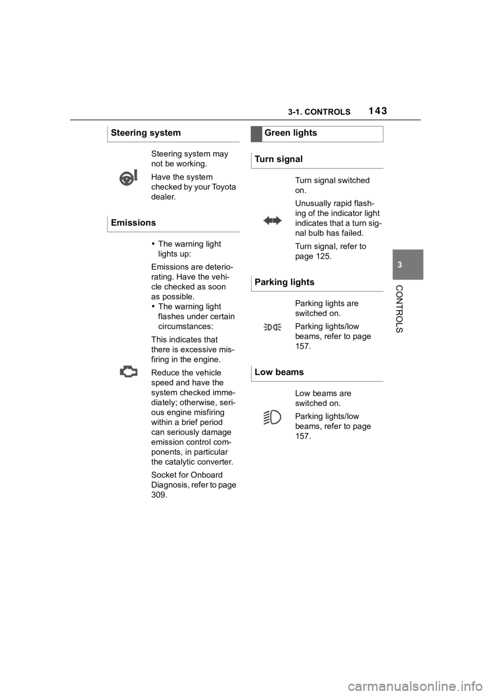
Steering system
Steering system may
not be working.
Have the system
checked by your Toyota
dealer.
Emissions
The warning light
lights up:
Emissions are deterio-
rating. Have the vehi-
cle checked as soon
as possible.
The warning light
flashes under certain
circumstances:
This indicates that
there is excessive mis-
firing in the engine.
Reduce the vehicle
speed and have the
system checked imme-
diately; otherwise, seri-
ous engine misfiring
within a brief period
can seriously damage
emission control com-
ponents, in particular
the catalytic converter.
Socket for Onboard
Diagnosis, refer to page
309.
Green lights
Turn signal
Turn signal switched
on.
Unusually rapid flash-
ing of the indicator light
indicates that a turn sig-
nal bulb has failed.
Turn signal, refer to
page 125.
Parking lights
Parking lights are
switched on.
Parking lights/low
beams, refer to page
157.
Low beams
Low beams are
switched on.
Parking lights/low
beams, refer to page
157.
Page 144 of 372
1443-1. CONTROLS
The current fill level of the fuel
tank is displayed.
Vehicle tilt position may cause
the display to vary.
Information on refueling, refer to
page 268.
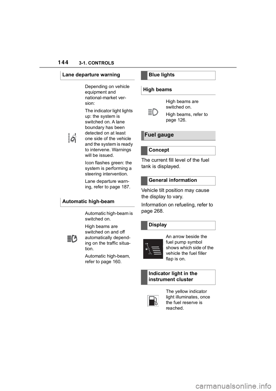
Lane departure warning
Depending on vehicle
equipment and
national-market ver-
sion:
The indicator light lights
up: the system is
switched on. A lane
boundary has been
detected on at least
one side of the vehicle
and the system is ready
to intervene. Warnings
will be issued.
Icon flashes green: the
system is performing a
steering intervention.
Lane departure warn-
ing, refer to page 187.
Automatic high-beam
Automatic high-beam is
switched on.
High beams are
switched on and off
automatically depend-
ing on the traffic situa-
tion.
Automatic high-beam,
refer to page 160.
Blue lights
High beams
High beams are
switched on.
High beams, refer to
page 126.
Fuel gauge
Concept
General information
Display
An arrow beside the
fuel pump symbol
shows which side of the
vehicle the fuel filler
flap is on.
Indicator light in the
instrument cluster
The yellow indicator
light illuminates, once
the fuel reserve is
reached.
Page 145 of 372
1453-1. CONTROLS
3
CONTROLS
Always avoid engine speeds in
the red warning field. In this
range, the fuel supply is reduced
to protect the engine.
Depending on the vehicle equip-
ment, the shift position indica-
tors on the instrument cluster
indicates the maximum shift
point at which the best possible
acceleration can be achieved.
Depending on the equipment
and nationalmarket version, the
Shift lights are active in the sport
mode of the Automatic transmis-
sion and with manual transmis-
sion.
When the selected driving mode
is sport mode, a shift light will be
displayed.
Automatic transmission:
1Select SPORT using the
sport mode switch.
2 Activate manual mode of the
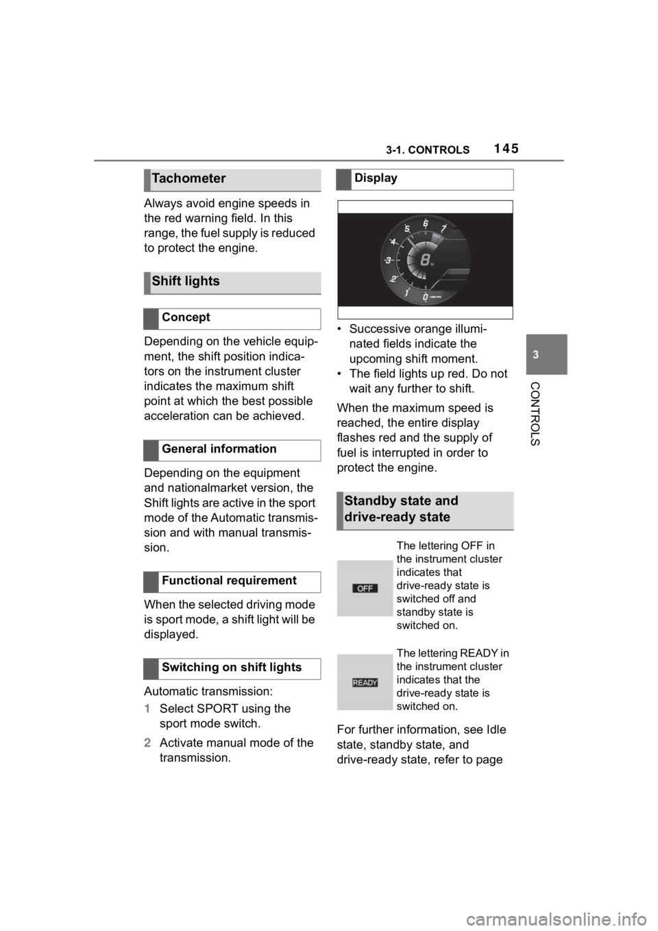
transmission. • Successive orange illumi-
nated fields indicate the
upcoming shift moment.
• The field lights up red. Do not wait any further to shift.
When the maximum speed is
reached, the entire display
flashes red and the supply of
fuel is interrupted in order to
protect the engine.
For further information, see Idle
state, standby state, and
drive-ready state, refer to page
Tachometer
Shift lights
Concept
General information
Functional requirement
Switching on shift lights
Display
Standby state and
drive-ready state
The lettering OFF in
the instrument cluster
indicates that
drive-ready state is
switched off and
standby state is
switched on.
The lettering READY in
the instrument cluster
indicates that the
drive-ready state is
switched on.
Page 146 of 372
1463-1. CONTROLS
45.If the indicator drops to
+37°F/+3°C or lower, a signal
sounds.
A vehicle message is displayed.
There is an increased risk of ice
on roads.
The time is displayed in the
instrument cluster. Setting the
time and time format, refer to
page 63.
The range indicates the dis-
tance that can still be covered
with the current fuel level.
The estimated range available
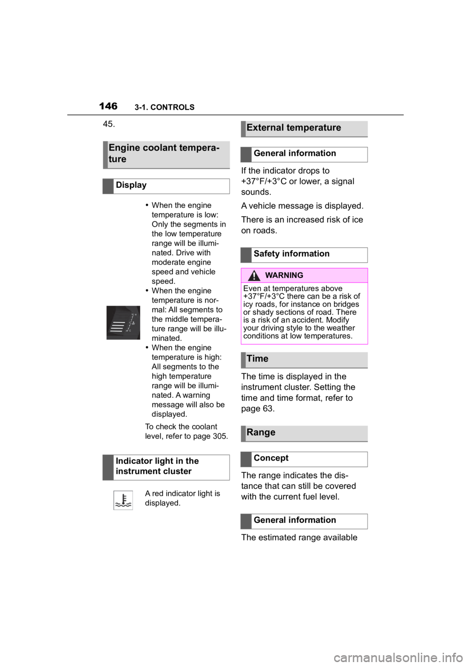
Engine coolant tempera-
ture
Display
When the engine
temperature is low:
Only the segments in
the low temperature
range will be illumi-
nated. Drive with
moderate engine
speed and vehicle
speed.
When the engine
temperature is nor-
mal: All segments to
the middle tempera-
ture range will be illu-
minated.
When the engine
temperature is high:
All segments to the
high temperature
range will be illumi-
nated. A warning
message will also be
displayed.
To check the coolant
level, refer to page 305.
Indicator light in the
instrument cluster
A red indicator light is
displayed.
External temperature
General information
Safety information
WARNING
Even at temper atures above
+37°F/+3°C there can be a risk of
icy roads, for instance on bridges
or shady sections of road. There
is a risk of an accident. Modify
your driving style to the weather
conditions at low temperatures.
Time
Range
Concept
General information
Page 155 of 372
1553-1. CONTROLS
3
CONTROLS
Various views are available for
the Head-up Display.
Via Toyota Supra Command:
1"My vehicle"
2 "System settings"
3 "Displays"
4 "Head-up display"
5 Select the desired setting.
The brightness adapts automati-
cally to the ambient brightness.
The basic setting can be
adjusted manually.
Via Toyota Supra Command:
1 "My vehicle"
2 "System settings"
3 "Displays"
4 "Head-up display"
5 "Brightness"
6 Turn the Controller until the
desired brightness is set.
7 Press the Controller.
When the low beams are
switched on, the brightness of
the Head-up Display can be
additionally influenced using the
instrument lighting.
Via Toyota Supra Command:
1 "My vehicle" 2
"System settings"
3 "Displays"
4 "Head-up display"
5 "Height"
6 Turn the Controller until the
desired height is reached.
7 Press the Controller.
The height of the Head-up Dis-
play can also be stored using
the memory function, refer to
page 111.
The Head-up Display view can
be rotated.
Via Toyota Supra Command:
1 "My vehicle"
2 "System settings"
3 "Displays"
4 "Head-up display"
5 "Rotation"
6 Turn the Controller until the
desired setting is selected.
7 Press the Controller.
The visibility of the displays in
the Head-up Display is influ-
enced by the following factors:
Seat position.
Objects on the protective
glass of the Head-up Display.
Dust or dirt on the protective
Selecting the view
Setting the brightness
Adjusting the height
Setting the rotation
Visibility of the display
Page 156 of 372
1563-1. CONTROLS
glass of the Head-up Display.
Windshield dirty on inside or
outside.
Sunglasses with certain polar-
ization filters.
Wet roads.
Unfavorable light conditions.
If the image is distorted, have
the basic settings checked by
your Toyota dealer.
The windshield is part of the
system.
The shape of the windshield
makes it possible to display a
precise image.
A film in the windshield prevents
double images from being gen-
erated.
For this reason, it is strongly
suggested to have the special
windshield replaced by your
Toyota dealer if necessary. This chapter describes all stan-
dard, country-specific and
optional features offered with
the series. It also describes fea-
tures and functions that are not
necessarily available in your
vehicle, e.g., due to the selected
options or country versions. This
also applies to safety-related
functions and systems. When
using these functions and sys-
tems, the applicable laws and
regulations must be observed.
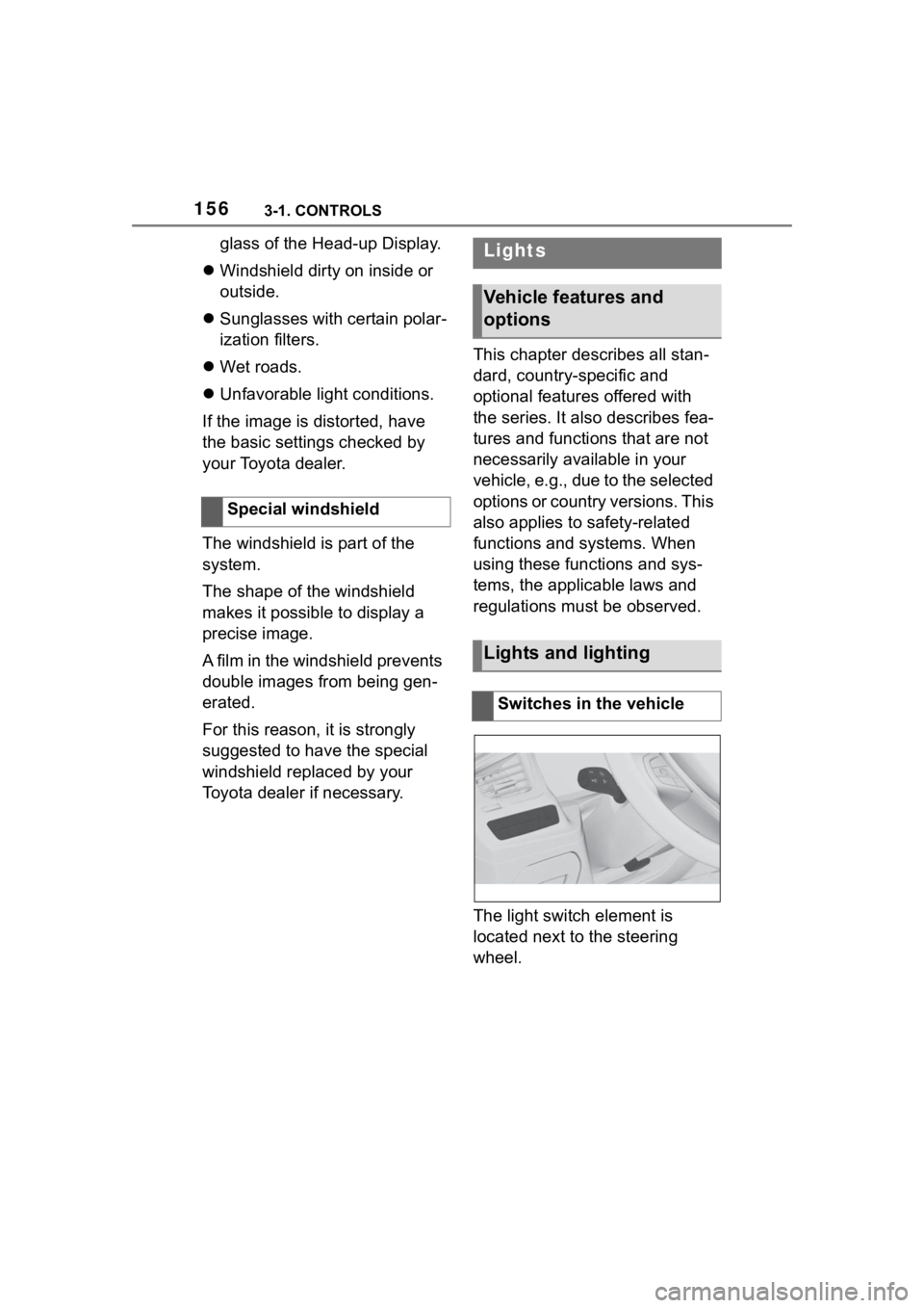
The light switch element is
located next to the steering
wheel.
Special windshieldLights
Vehicle features and
options
Lights and lighting
Switches in the vehicle
Page 157 of 372
1573-1. CONTROLS
3
CONTROLS
The low beams are switched on
and off automatically depending
on the ambient brightness, for
instance in tunnels, in twilight or
if there is precipitation.
A blue sky with the sun low on
the horizon can cause the lights to be switched on.
If the low beams are switched
on manually, the automatic
headlight control is deactivated.
The LED in the button lights up.
The automatic headlight control
cannot serve as a substitute for
your personal judgment of light-
ing conditions.
For example, the sensors are
unable to detect fog or hazy
weather. In these situations,
switch the light on manually.
If the driver's door is opened
when the drive-ready state is
switched off, the exterior lighting
is automatically switched off
after a period of time.
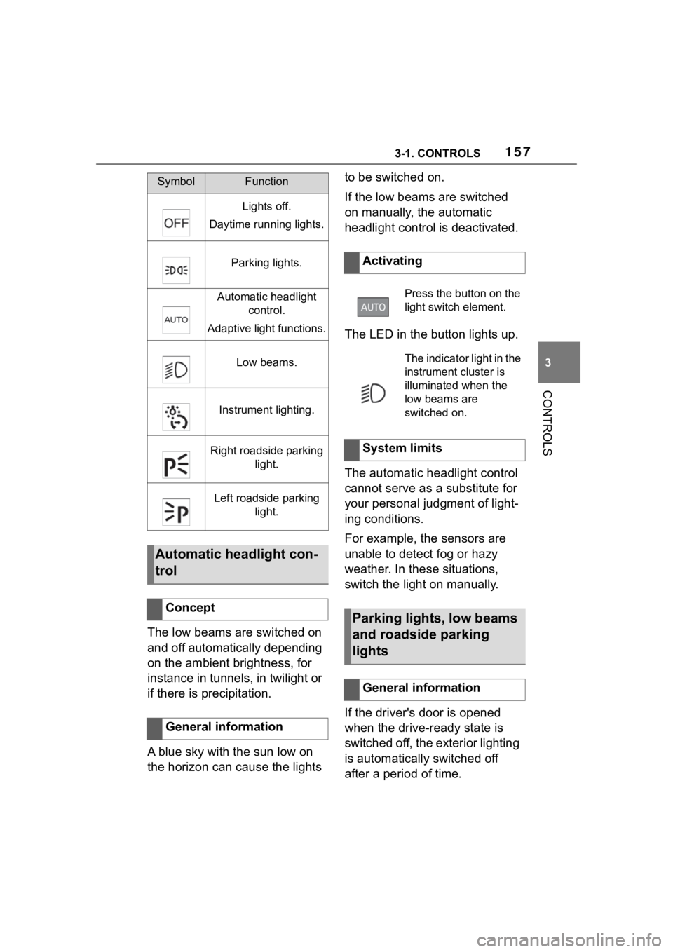
SymbolFunction
Lights off.
Daytime running lights.
Parking lights.
Automatic headlight control.
Adaptive light functions.
Low beams.
Instrument lighting.
Right roadside parking light.
Left roadside parking light.
Automatic headlight con-
trol
Concept
General information
Activating
Press the button on the
light switch element.
The indicator light in the
instrument cluster is
illuminated when the
low beams are
switched on.
System limits
Parking lights, low beams
and roadside parking
lights
General information