TOYOTA TUNDRA 2018 Owners Manual (in English)
Manufacturer: TOYOTA, Model Year: 2018, Model line: TUNDRA, Model: TOYOTA TUNDRA 2018Pages: 672, PDF Size: 14.09 MB
Page 561 of 672
5618-2. Steps to take in an emergency
8
When trouble arises
(If equipped)
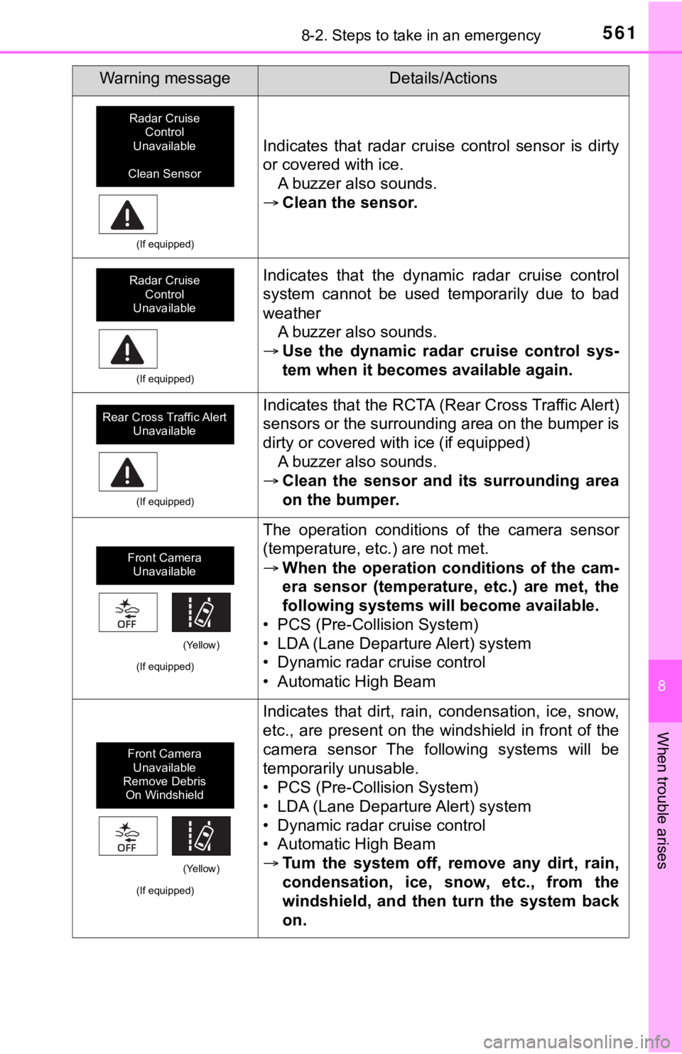
Indicates that radar cruise control sensor is dirty
or covered with ice.A buzzer also sounds.
Clean the sensor.
(If equipped)
Indicates that the dynamic radar cruise control
system cannot be used temporarily due to bad
weather
A buzzer also sounds.
Use the dynamic radar cruise control sys-
tem when it becomes available again.
(If equipped)
Indicates that the RCTA (Rear Cross Traffic Alert)
sensors or the surrounding area on the bumper is
dirty or covered with ice (if equipped)
A buzzer also sounds.
Clean the sensor and its surrounding area
on the bumper.
(If equipped)
The operation conditions of the camera sensor
(temperature, etc.) are not met.
When the operation conditions of the cam-
era sensor (temperature, etc.) are met, the
following systems will become available.
• PCS (Pre-Collision System)
• LDA (Lane Departure Alert) system
• Dynamic radar cruise control
• Automatic High Beam
(If equipped)
Indicates that dirt, rain, condensation, ice, snow,
etc., are present on the windshield in front of the
camera sensor The following systems will be
temporarily unusable.
• PCS (Pre-Collision System)
• LDA (Lane Departure Alert) system
• Dynamic radar cruise control
• Automatic High Beam
Tum the system off, remove any dirt, rain,
condensation, ice, snow, etc., from the
windshield, and then turn the system back
on.
Warning messageDetails/Actions
Radar Cruise
Control
Unavailable
Clean Sensor
Radar Cruise Control
Unavailable
Rear Cross Traffic Alert Unavailable
Front Camera Unavailable
(Yellow)
Front Camera
Unavailable
Remove Debris On Windshield
(Yellow)
Page 562 of 672
5628-2. Steps to take in an emergency
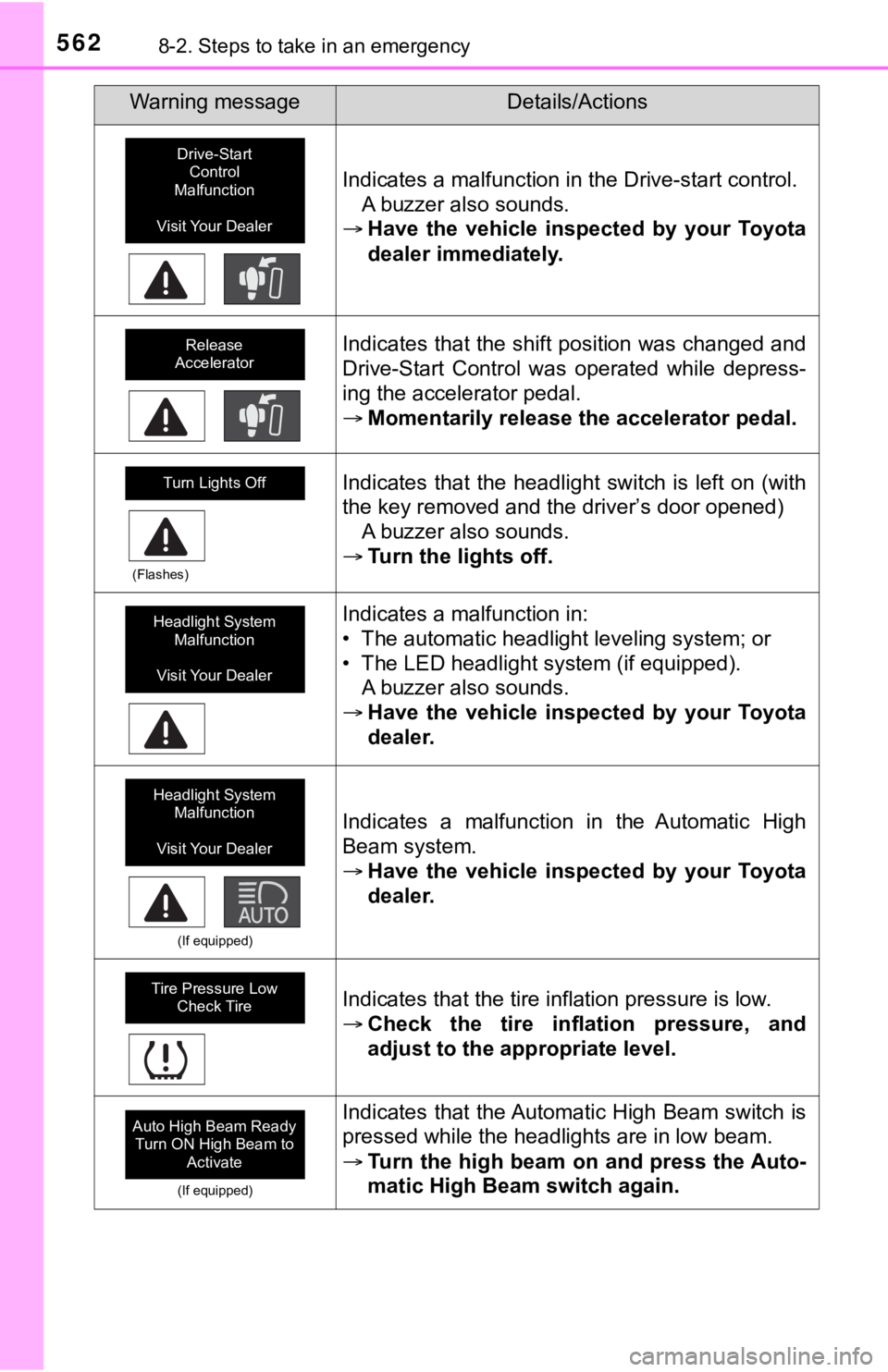
Indicates a malfunction in the Drive-start control.A buzzer also sounds.
Have the vehicle inspected by your Toyota
dealer immediately.
Indicates that the shift position was changed and
Drive-Start Control was operated while depress-
ing the accelerator pedal.
Momentarily release the accelerator pedal.
(Flashes)
Indicates that the headlight switch is left on (with
the key removed and the driver’s door opened)
A buzzer also sounds.
Turn the lights off.
Indicates a malfunction in:
• The automatic headlight leveling system; or
• The LED headlight system (if equipped).
A buzzer also sounds.
Have the vehicle inspected by your Toyota
dealer.
(If equipped)
Indicates a malfunction in the Automatic High
Beam system.
Have the vehicle inspected by your Toyota
dealer.
Indicates that the tire inflation pressure is low.
Check the tire inflation pressure, and
adjust to the appropriate level.
(If equipped)
Indicates that the Automatic High Beam switch is
pressed while the headlights are in low beam.
Turn the high beam on and press the Auto-
matic High Beam switch again.
Warning messageDetails/Actions
Drive-Start
Control
Malfunction
Visit Your Dealer
Release
Accelerator
Turn Lights Off
Headlight System Malfunction
Visit Your Dealer
Headlight System Malfunction
Visit Your Dealer
Tire Pressure Low Check Tire
Auto High Beam Ready Turn ON High Beam to
Activate
Page 563 of 672
5638-2. Steps to take in an emergency
8
When trouble arises
(If equipped)
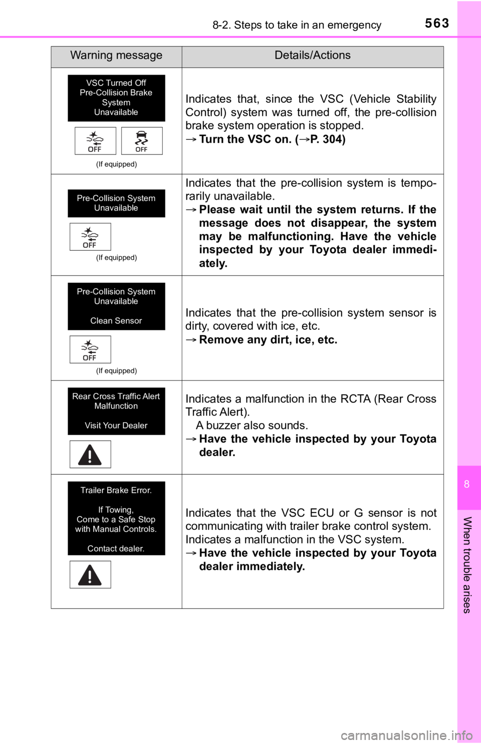
Indicates that, since the VSC (Vehicle Stability
Control) system was turned off, the pre-collision
brake system operation is stopped.
Turn the VSC on. ( P. 304)
(If equipped)
Indicates that the pre-collision system is tempo-
rarily unavailable.
Please wait until the system returns. If the
message does not disappear, the system
may be malfunctioning. Have the vehicle
inspected by your Toyota dealer immedi-
ately.
(If equipped)
Indicates that the pre-collision system sensor is
dirty, covered with ice, etc.
Remove any dirt, ice, etc.
Indicates a malfunction in the RCTA (Rear Cross
Traffic Alert).
A buzzer also sounds.
Have the vehicle inspected by your Toyota
dealer.
Indicates that the VSC ECU or G sensor is not
communicating with trailer brake control system.
Indicates a malfunction in the VSC system.
Have the vehicle inspected by your Toyota
dealer immediately.
Warning messageDetails/Actions
VSC Turned Off
Pre-Collision Brake
System
Unavailable
Pre-Collision System Unavailable
Pre-Collision System Unavailable
Clean Sensor
Rear Cross Traffic Alert Malfunction
Visit Your Dealer
Trailer Brake Error. If Towing,
Come to a Safe Stop
with Manual Controls.
Contact dealer.
Page 564 of 672
5648-2. Steps to take in an emergency
*: Refer to the separate “Scheduled Maintenance Guide” or “Owner’s Manual
Supplement” for the maintenance interval applicable to your veh icle.
■Conditions that the tire pressure warning system may not functi on
properly
P. 5 0 1
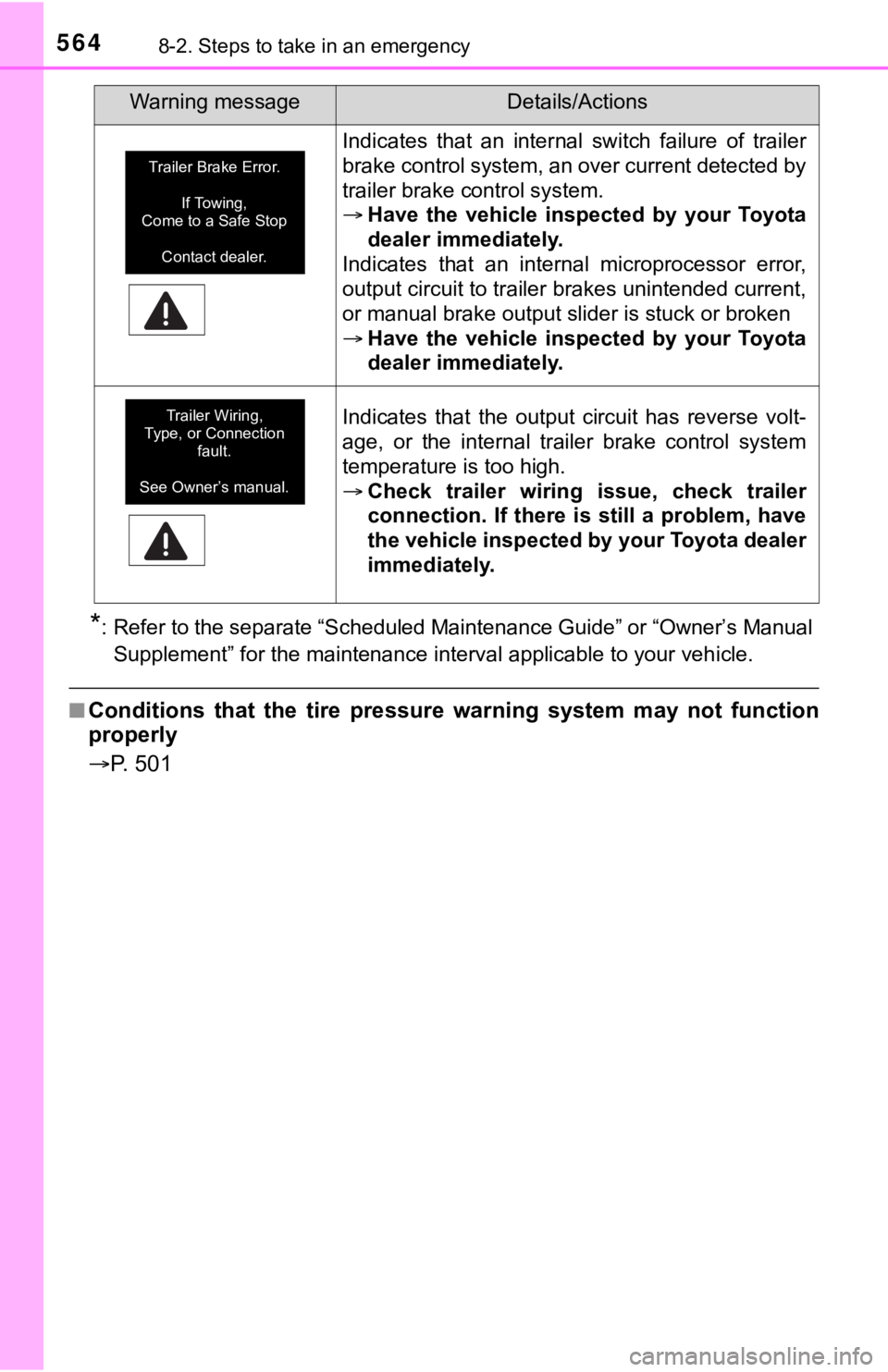
Indicates that an internal switch failure of trailer
brake control system, an over current detected by
trailer brake control system.
Have the vehicle inspected by your Toyota
dealer immediately.
Indicates that an internal microprocessor error,
output circuit to trailer brakes unintended current,
or manual brake output slider is stuck or broken
Have the vehicle inspected by your Toyota
dealer immediately.
Indicates that the output circuit has reverse volt-
age, or the internal trailer brake control system
temperature is too high.
Check trailer wiring issue, check trailer
connection. If there is still a problem, have
the vehicle inspected by your Toyota dealer
immediately.
Warning messageDetails/Actions
Trailer Brake Error.
If Towing,
Come to a Safe Stop
Contact dealer.
Trailer Wiring,
Type, or Connection
fault.
See Owner’s manual.
Page 565 of 672
565
8
When trouble arises
8-2. Steps to take in an emergency
If you have a flat tire
●Stop the vehicle in a safe place on a hard, flat surface.
● Set the parking brake.
● Shift the shift lever to P.
● Stop the engine.
● Turn on the emergency flashers. ( P. 538)
Your vehicle is equipped with a spare tire. The flat tire can b e
replaced with the spare tire.
For details about tires: P. 4 9 5
WARNING
■If you have a flat tire
Do not continue driving with a flat tire.
Driving even a short distance wit h a flat tire can damage the tire and the
wheel beyond repair, which cou ld result in an accident.
Before jacking up the vehicle
Page 566 of 672
5668-2. Steps to take in an emergency
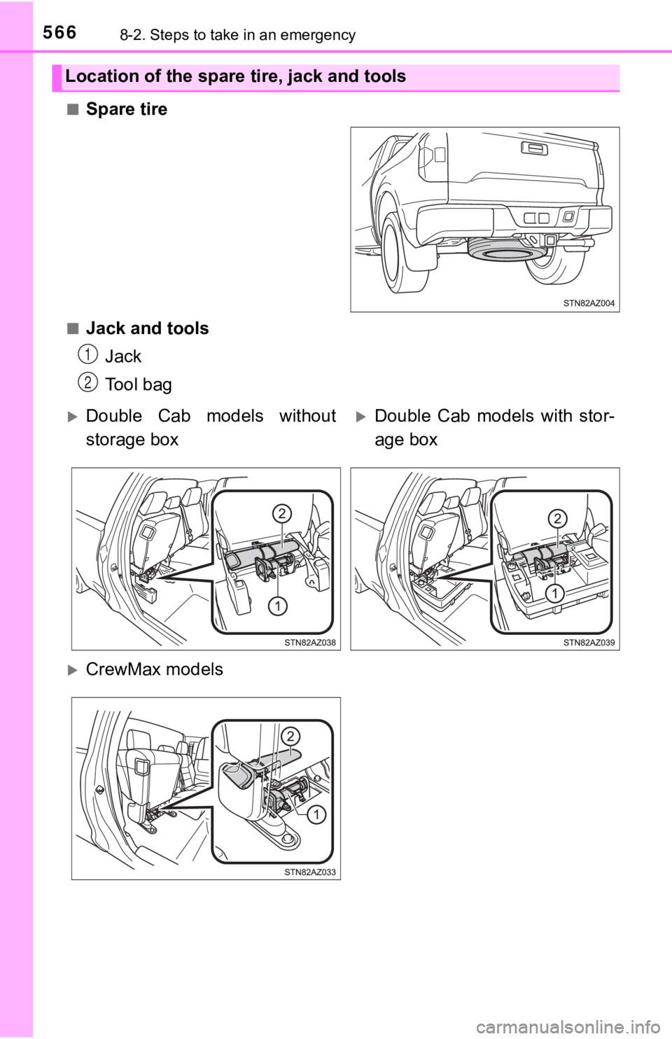
■Spare tire
■Jack and toolsJack
Tool bag
Location of the spare tire, jack and tools
1
2
Double Cab models without
storage boxDouble Cab models with stor-
age box
CrewMax models
Page 567 of 672

5678-2. Steps to take in an emergency
8
When trouble arises
WARNING
■Using the tire jack
Observe the following precautions.
Improper use of the tire jack may cause the vehicle to suddenly fall off
the jack, leading to death or serious injury.
●Do not use the tire jack for any purpose other than replacing t ires or
installing and removing tire chains.
●Only use the tire jack that comes with this vehicle for replacing a flat
tire.
Do not use it on other vehicles, and do not use other tire jack s for
replacing tires on this vehicle.
●Put the jack properl y in its jack point.
●Do not put any part of your body under the vehicle while it is supported
by the jack.
●Do not start the engine or drive the vehicle while the vehicle is sup-
ported by the jack.
●Do not raise the vehicle w hile someone is inside.
●When raising the vehicle, do not put an object on or under the jack.
●Do not raise the vehicle to a height greater than that required to
replace the tire.
●Use a jack stand if it is nece ssary to get under the vehicle.
●When lowering the vehicle, make sure that there is no-one near the
vehicle. If there are people nearb y, warn them vocally before lowering.
■Using the jack handle
Insert the square head securely until you hear a click to preve nt the
extension parts from com ing apart unexpectedly.
Page 568 of 672
5688-2. Steps to take in an emergency
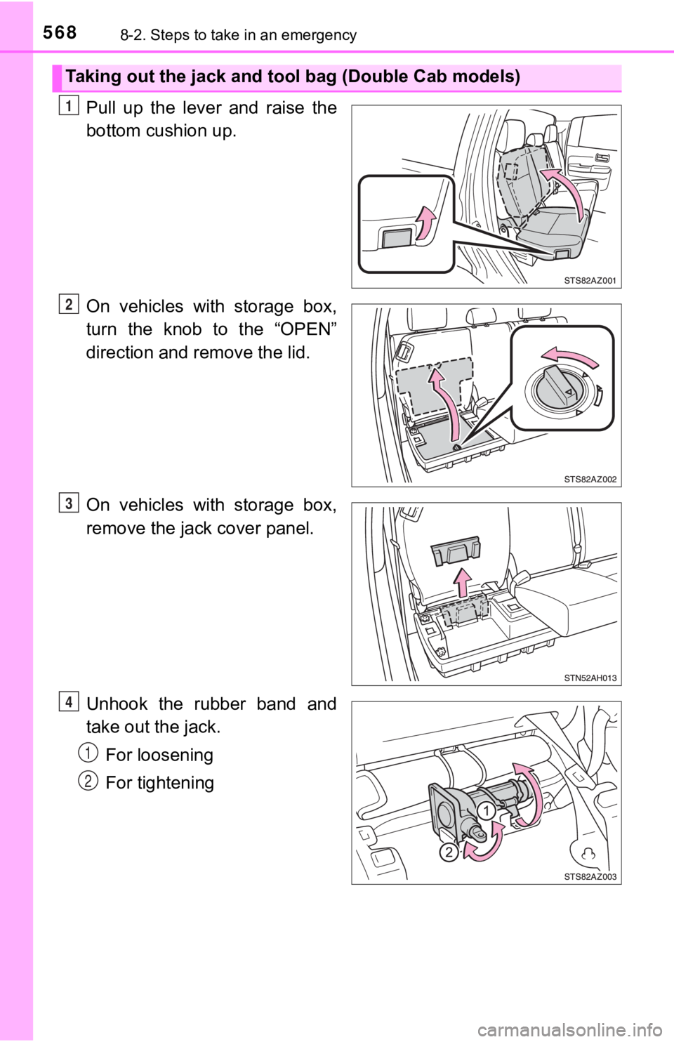
Pull up the lever and raise the
bottom cushion up.
On vehicles with storage box,
turn the knob to the “OPEN”
direction and remove the lid.
On vehicles with storage box,
remove the jack cover panel.
Unhook the rubber band and
take out the jack.For loosening
For tightening
Taking out the jack and tool bag (Double Cab models)
1
2
3
4
1
2
Page 569 of 672
5698-2. Steps to take in an emergency
8
When trouble arises
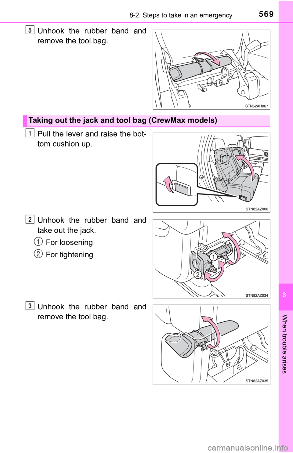
Unhook the rubber band and
remove the tool bag.
Pull the lever and raise the bot-
tom cushion up.
Unhook the rubber band and
take out the jack.For loosening
For tightening
Unhook the rubber band and
remove the tool bag.5
Taking out the jack and t ool bag (CrewMax models)
1
2
1
2
3
Page 570 of 672
5708-2. Steps to take in an emergency
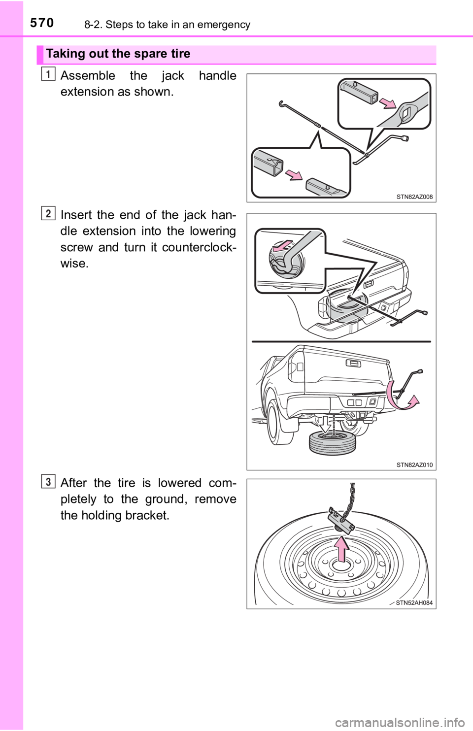
Assemble the jack handle
extension as shown.
Insert the end of the jack han-
dle extension into the lowering
screw and turn it counterclock-
wise.
After the tire is lowered com-
pletely to the ground, remove
the holding bracket.
Taking out the spare tire
1
2
3