brake TOYOTA YARIS 2022 Owners Manual
[x] Cancel search | Manufacturer: TOYOTA, Model Year: 2022, Model line: YARIS, Model: TOYOTA YARIS 2022Pages: 590, PDF Size: 128.6 MB
Page 5 of 590
3
HV Owner's Manual_Europe_M52N30_en
TABLE OF CONTENTS
1
6
5
4
3
2
8
7
3-5. Opening and closing the win-
dows
Power windows ................... 156
4-1. Before driving
Driving the vehicle .............. 160
Cargo and luggage ............. 166
Trailer towing (vehicles without
towing packages - including
Reunion) ........................... 167
Trailer towing (vehicles with tow-
ing packages - except for
Reunion) ........................... 167
4-2. Driving procedures
Power (ignition) s witch (vehicles
without a smart entry & start
system) ............................. 173
Power (ignition) s witch (vehicles
with a smart entry & start sys-
tem) .................................. 175
EV drive mode .................... 179
Hybrid transmission ............ 181
Turn signal lever ................. 184
Parking brake...................... 184
Brake Hold .......................... 187
4-3. Operating the lights and wip-
ers
Headlight switch.................. 190
AHB (Automatic High Beam)
.......................................... 193
Fog light switch ................... 196
Windshield wipers and washer
.......................................... 197
Rear window wiper and washer
.......................................... 200
4-4. Refueling
Opening the fuel tank cap ... 202
4-5. Using the driving support sys-
tems
Toyota Safety Sense ........... 204
PCS (Pre-Collision System) 209
LTA (Lane Tracing Assist) ... 220
Dynamic radar cruise control
with full-speed range ........ 230
Speed limiter ....................... 242
RSA (Road Sign Assist) ...... 244
BSM (Blind Spot Monitor) ... 248
Toyota parking assist-sensor
.......................................... 253
RCTA (Rear Crossing Traffic
Alert) ................................. 260
PKSB (Parking Support Brake)
.......................................... 265
Parking Support Brake function
(static objects) .................. 270
Parking Support Brake function
(rear-crossing vehicles) .... 273
Driving mode select switch . 275
GPF (Gasoline Particulate Filter)
system .............................. 276
Driving assist systems ........ 277
4-6. Driving tips
Hybrid vehicle driving tips ... 282
Winter driving tips ............... 284
4Driving
Page 8 of 590
6
HV Owner's Manual_Europe_M52N30_en
Please note that this manual
applies to all models and explains
all equipment, including options.
Therefore, you may find some
explanations for equipment not
installed on your vehicle.
All specifications provided in this
manual are current at the time of
printing. However, because of the
Toyota policy of continual product
improvement, we reserve the right
to make changes at any time with-
out notice.
Depending on specifications, the
vehicle shown in the illustrations
may differ from your vehicle in
terms of equipment.
Both genuine Toyota and a wide
variety of other spare parts and
accessories for Toyota vehicles are
currently available on the market.
Should it be determined that any of
the genuine Toyota parts or acces-
sories supplied with the vehicle
need to be replaced, Toyota recom-
mends that genuine Toyota parts or
accessories, be used to replace
them. Other parts or accessories of
matching quality can also be used.
Toyota cannot accept any liability or
guarantee spare parts and acces-
sories which are not genuine
Toyota products, nor for replace-
ment or installation involving such
parts. In addition, damage or per-
formance problems resulting from
the use of non-genuine Toyota
spare parts or accessories may not
be covered under warranty.
Also, remodeling like this will have
an effect on advanced safety equip-
ment such as Toyota Safety Sense
and there is a danger that it will not
work properly or the danger that it
may work in situations where it
should not be working.
The installation of an RF-transmit-
ter system in your vehicle could
affect electronic systems such as:
Hybrid system
Multiport fuel injection sys-
tem/sequential multiport fuel
injection system
Toyota Safety Sense (if
equipped)
Dynamic radar cruise control
with full-speed range (if
equipped)
Anti-lock brake system
SRS airbag system
Seat belt pretensioner system
Be sure to check with any autho-
rized Toyota retailer or Toyota
For your information
Main Owner’s Manual
Accessories, spare parts
and modification of your
To y o t a
Installation of an RF-trans-
mitter system
Page 9 of 590
7
HV Owner's Manual_Europe_M52N30_en
authorized repairer, or any reliable
repairer for precautionary mea-
sures or special instructions regard-
ing installation of an RF-transmitter
system.
Further information regarding fre-
quency bands, power levels,
antenna positions and installation
provisions for the installation of RF-
transmitters, is available on request
at any authorized Toyota retailer or
Toyota authorized repairer, or any
reliable repairer.
High voltage parts and cables on
the hybrid vehicles emit approxi-
mately the same amount of electro-
magnetic waves as the
conventional gasoline powered
vehicles or home electronic appli-
ances despite of their electromag-
netic shielding.
Unwanted noise may occur in the
reception of the radio frequency
transmitter (RF-transmitter).
The vehicle is equipped with
sophisticated computers that will
record certain data, such as:
• Engine speed/Electric motor
speed (traction motor speed)
• Accelerator status
• Brake status
• Vehicle speed
• Operation status of the driving
assist systems
• Images from the cameras
Your vehicle is equipped with cameras.
Contact any authorized Toyota retailer
or Toyota authorized repairer, or any
reliable repairer for the location of
recording cameras.
The recorded data varies according
to the vehicle grade level, options
and destinations with which it is
equipped.
These computers do not record
conversations or sounds, and only
record images outside of the vehi-
cle in certain situations.
Data usage
Toyota may use the data recorded in
this computer to diagnose malfunc-
tions, conduct research and develop-
ment, and improve quality.
Toyota will not disclose the recorded
data to a third party except:
• With the consent of the vehicle owner
or with the consent of the lessee if
the vehicle is leased
• In response to an official request by
the police, a court of law or a govern-
ment agency
• For use by Toyota in a lawsuit
• For research purposes where the
data is not tied to a specific vehicle or
vehicle owner
Recorded image information can
be erased by any authorized
Toyota retailer or Toyota autho-
rized repairer, or any reliable
repairer.
The image recording function can be
disabled. However, if the function is dis-
abled, data from when the system oper-
ates will not be available.
Vehicle data recording
Page 18 of 590

16
HV Owner's Manual_Europe_M52N30_en
Pictorial index
■Switches (left-hand drive vehicles)
Outside rear view mirror switches ...............................................P.153
Window lock switch ............................................. ..........................P.158
Door lock switches ............................................. ...........................P.136
Power window switches .......................................... ......................P.156
Headlight leveling dial ........................................ ...........................P.192
Automatic High Beam switch*......................................................P.193
Heated steering wheel switch*......................................................P.294
Driving mode select switch..................................... ......................P.275
VSC OFF switch ................................................. ............................P.278
EV drive mode switch ........................................... .........................P.179
Brake hold switch .............................................. ............................P.187
Parking brake switch ........................................... ..........................P.184
Page 25 of 590
23
HV Owner's Manual_Europe_M52N30_en
Pictorial index
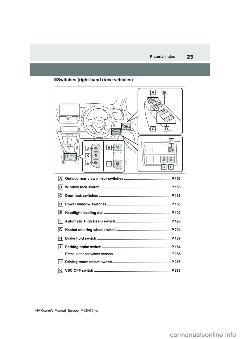
■Switches (right-hand drive vehicles)
Outside rear view mirror switches ...............................................P.153
Window lock switch ............................................. ..........................P.158
Door lock switches ............................................. ...........................P.136
Power window switches .......................................... ......................P.156
Headlight leveling dial ........................................ ...........................P.192
Automatic High Beam switch ..................................... ..................P.193
Heated steering wheel switch*......................................................P.294
Brake hold switch .............................................. ............................P.187
Parking brake switch ........................................... ..........................P.184
Precautions for winter season.................................. ........................P.285
Driving mode select switch..................................... ......................P.275
VSC OFF switch ................................................. ............................P.278
Page 40 of 590
38
HV Owner's Manual_Europe_M52N30_en
1-1. For safe use
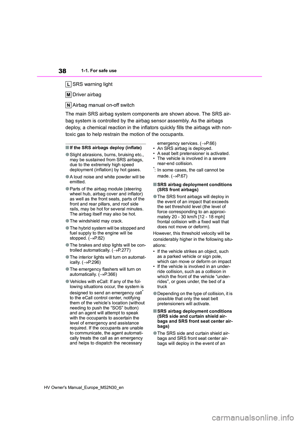
SRS warning light
Driver airbag
Airbag manual on-off switch
The main SRS airbag system components are shown above. The SRS air-
bag system is controlled by the airbag sensor assembly. As the airbags
deploy, a chemical reaction in the inflators quickly fills the airbags with non-
toxic gas to help restrain the motion of the occupants.
■If the SRS airbags deploy (inflate)
●Slight abrasions, burns, bruising etc., may be sustained from SRS airbags, due to the extremely high speed
deployment (inflation) by hot gases.
●A loud noise and white powder will be emitted.
●Parts of the airbag module (steering wheel hub, airbag cover and inflator) as well as the front seats, parts of the
front and rear pillars, and roof side rails, may be hot for several minutes. The airbag itself may also be hot.
●The windshield may crack.
●The hybrid system will be stopped and fuel supply to the engine will be stopped. ( P.82)
●The brakes and stop lights will be con- trolled automatically. ( P.277)
●The interior lights will turn on automat- ically. ( P.296)
●The emergency flashers will turn on automatically. ( P.366)
●Vehicles with eCall: If any of the fol-
lowing situations occur, the system is
designed to send an emergency call* to the eCall control center, notifying them of the vehicle’s location (without
needing to push the “SOS” button) and an agent will attempt to speak with the occupants to ascertain the
level of emergency and assistance required. If the occupants are unable to communicate, the agent automati-
cally treats the call as an emergency and helps to dispatch the necessary
emergency services. ( P.66)
• An SRS airbag is deployed. • A seat belt pretensioner is activated.• The vehicle is involved in a severe
rear-end collision.*: In some cases, the call cannot be
made. ( P. 6 7 )
■SRS airbag deployment conditions (SRS front airbags)
●The SRS front airbags will deploy in the event of an impact that exceeds the set threshold level (the level of
force corresponding to an approxi- mately 20 - 30 km/h [12 - 18 mph] frontal collision with a fixed wall that
does not move or deform).
However, this threshold velocity will be
considerably higher in the following situ-
ations:
• If the vehicle strikes an object, such as a parked vehicle or sign pole,
which can move or deform on impact • If the vehicle is involved in an under-ride collision, such as a collision in
which the front of the vehicle “under- rides”, or goes under, the bed of a truck
●Depending on the type of collision, it is possible that only the seat belt
pretensioners will activate.
■SRS airbag deployment conditions (SRS side and curtain shield air-bags and SRS front seat center air-
bags)
●The SRS side and curtain shield air-
bags and SRS front seat center air- bags will deploy in the event of an
Page 79 of 590
77
1
HV Owner's Manual_Europe_M52N30_en
1-4. Hybrid system
For safety and security
hybrid battery (traction battery) is
not being charged.
*: When the hybrid battery (traction bat-
tery) requires charging or the engine
is warming up, etc., the gasoline
engine will not automatically stop.
( P. 7 7 )
■During normal driving
The gasoline engine is predomi-
nantly used. The electric motor
(traction motor) charges the hybrid
battery (traction battery) as neces-
sary.
■When accelerating sharply
When the accelerator pedal is
depressed heavily, the power of the
hybrid battery (traction battery) is
added to that of the gasoline engine
via the electric motor (traction
motor).
■When braking (regenerative
braking)
The wheels operate the electric
motor (traction motor) as a power
generator, and the hybrid battery
(traction battery) is charged.
■Regenerative braking
●In the following situations, kinetic energy is converted to electric energy
and deceleration force can be obtained in conjunction with the recharging of the hybrid battery (trac-
tion battery). • The accelerator pedal is released while driving with the shift lever in D or
B. • The brake pedal is depressed while driving with the shift lever in D or B.
●Vehicles with GPF system: While the GPF system ( P.276) is operating to
regenerate the exhaust gas filter, the
hybrid battery (traction battery) may not be recharged.
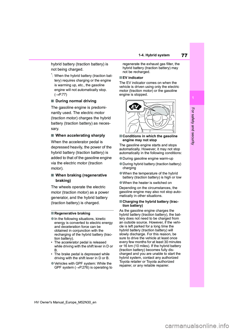
■EV indicator
The EV indicator comes on when the
vehicle is driven using only the electric motor (traction motor) or the gasoline engine is stopped.
■Conditions in which the gasoline engine may not stop
The gasoline engine starts and stops automatically. However, it may not stop automatically in the following conditions:
●During gasoline engine warm-up
●During hybrid battery (traction battery) charging
●When the temperature of the hybrid battery (traction battery) is high or low
●When the heater is switched on
Depending on the circumstances, the gasoline engine may also not stop auto-
matically in other situations.
■Charging the hybrid battery (trac- tion battery)
As the gasoline engine charges the
hybrid battery (traction battery), the bat- tery does not need to be charged from an outside source. However, if the vehi-
cle is left parked for a long time the hybrid battery (traction battery) will slowly discharge. For this reason, be
sure to drive the vehicle at least once every few months for at least 30 minutes or 16 km (10 miles). If the hybrid battery
(traction battery) becomes fully dis- charged and you are unable to start the hybrid system, contact any authorized
Toyota retailer or Toyota authorized repairer, or any reliable repairer.
Page 80 of 590
78
HV Owner's Manual_Europe_M52N30_en
1-4. Hybrid system
■Charging the 12-volt battery
P. 4 1 1
■After the 12-volt battery has dis- charged or when the terminal has been removed and installed during
exchange, etc.
The gasoline engine may not stop even if the vehicle is being driven by the
hybrid battery (traction battery). If this continues for a few days, contact any authorized Toyota retailer or Toyota
authorized repairer, or any reliable repairer.
■Sounds and vibrations specific to a hybrid vehicle
There may be no engine sound or vibra- tion even though the vehicle is able to move with the “READY” indicator is illu-
minated. For safety, apply the parking brake and make sure to shift the shift lever to P when parked.
The following sounds or vibrations may occur when the hybrid system is operat-ing and are not a malfunction:
●Motor sounds may be heard from the engine compartment.
●Sounds may be heard from the hybrid battery (traction battery) under the
rear seats when the hybrid system starts or stops.
●Relay operating sounds such as a snap or soft clank will be emitted from the hybrid battery (traction battery),
under the rear seats, when the hybrid system is started or stopped.
●Sounds from the hybrid system may be heard when the back door is open.
●Sounds may be heard from the trans-mission when the gasoline engine starts or stops, when driving at low
speeds, or during idling.
●Engine sounds may be heard when
accelerating sharply.
●Sounds may be heard due to regener-
ative braking when the brake pedal is depressed or as the accelerator pedal is released.
●Vibration may be felt when the gaso-
line engine starts or stops.
●Cooling fan sounds may be heard
from the air intake vent on the side of the lower part of the rear left seat.
■Maintenance, repair, recycling, and disposal
Contact any authorized Toyota retailer or Toyota authorized repairer, or any reli-able repairer regarding maintenance,
repair, recycling and disposal. Do not dispose of the vehicle yourself.
■Customization
Some functions can be customized.
( P.431)
When the gasoline engine is off
while driving, a sound is produced
to warn pedestrians, people riding
bicycles or other people and vehi-
cles in the surrounding area that
the vehicle is approaching. The
pitch of the sound adjusts accord-
ing to vehicle speed. When vehicle
speed is approximately 25 km/h (16
mph) or more, the warning system
turns off.
■Acoustic vehicle alerting system
In the following cases, the acoustic vehi- cle alerting system sound may be diffi-
cult for pedestrians, people riding bicycles or other people and vehicles in the surrounding area to hear:
●When there is a lot of noise in the vicinity
●When it is raining or during strong winds
●When in the area surrounding the rear of the vehicle, rather than in front of
the vehicle
Acoustic vehicle alerting
system
Page 82 of 590
80
HV Owner's Manual_Europe_M52N30_en
1-4. Hybrid system
■Running out of fuel
When the vehicle has run out of fuel and
the hybrid system cannot be started, refuel the vehicle with at least enough gasoline to make the low fuel level warn-
ing light ( P.377) go off. If there is only a small amount of fuel, the hybrid sys-tem may not be able to start. (The stan-
dard amount of fuel is about 5.8 L [1.6 gal., 1.3 Imp. gal.] [vehicles without rear wiper] or 6.3 L [1.7 gal., 1.4 Imp. gal.]
[vehicles with rear wiper] when the vehi- cle is on a level surface. This value may vary when the vehicle is on a slope. Add
extra fuel when the vehicle is inclined.)
■Electromagnetic waves
●High voltage parts and cables on
hybrid vehicles incorporate electro- magnetic shielding, and therefore emit approximately the same amount of
electromagnetic waves as conven- tional gasoline powered vehicles or home electronic appliances.
●Your vehicle may cause sound inter-ference in some third party-produced
radio parts.
■Hybrid battery (traction battery)
The hybrid battery (traction battery) has a limited service life. The lifespan of the
hybrid battery (traction battery) can change in accordance with driving style
and driving conditions.
■Starting the hybrid system in an extremely cold environment
When the hybrid battery (traction bat-
tery) is extremely cold (below approxi- mately -30°C [-22°F]) under the influence of the outside temperature, it
may not be possible to start the hybrid system. In this case, try to start the hybrid system again after the tempera-
ture of the hybrid battery increases due to the outside temperature increase etc.
■Declaration of conformity
This model conforms to hydrogen emis-
sions according to regulation ECE100 (Battery electric vehicle safety).
WARNING
■High voltage precautions
This vehicle has high voltage DC and
AC systems as well as a 12-volt sys- tem. DC and AC high voltage is very dangerous and can cause severe
burns and electric shock that may result in death or serious injury.
●Never touch, disassemble, remove or replace the high voltage parts, cables or their connectors.
●The hybrid system will become hot after starting as the system uses
high voltage. Be careful of both the high voltage and the high tempera-ture, and always obey the warning
labels attached to the vehicle.
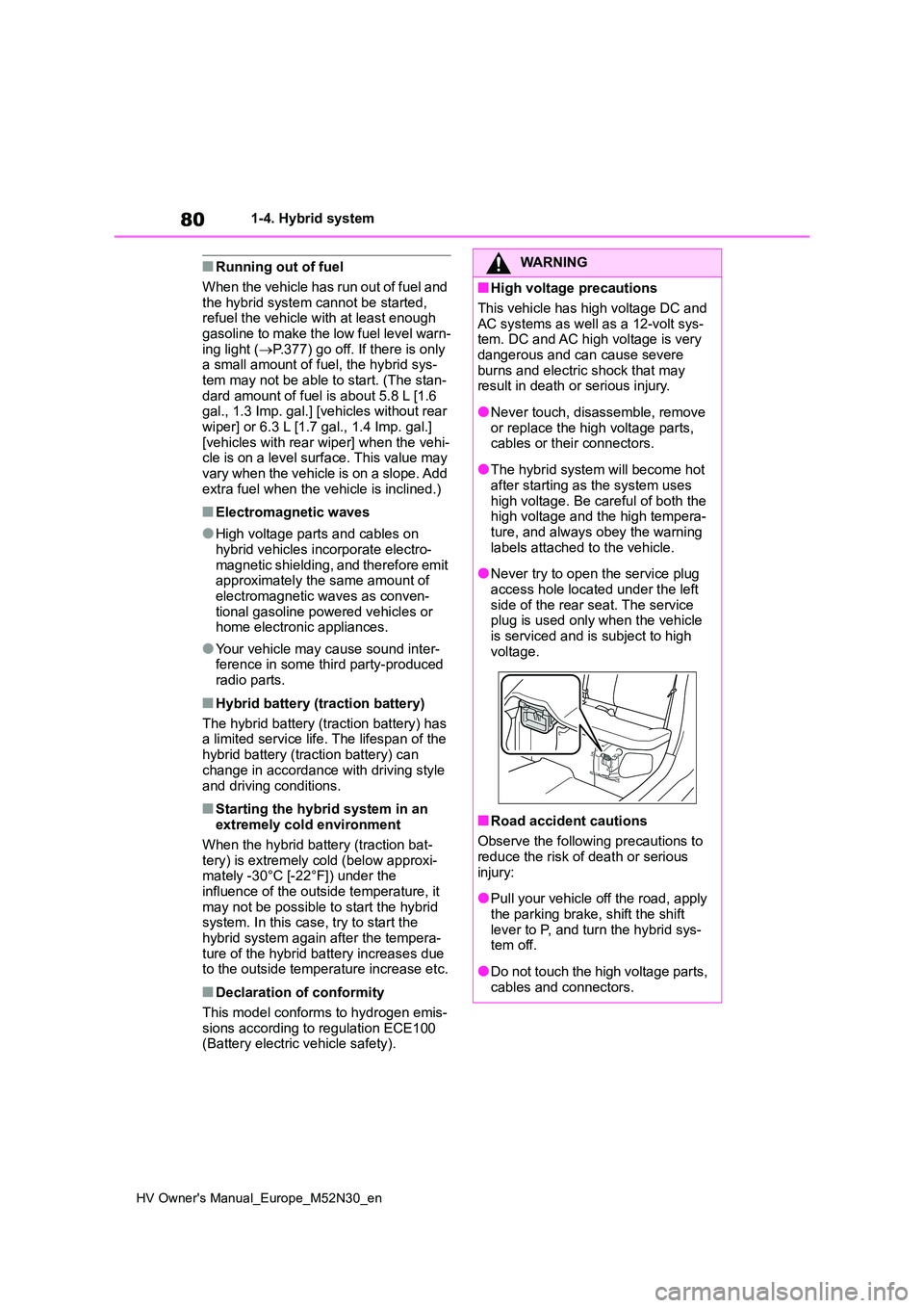
●Never try to open the service plug
access hole located under the left side of the rear seat. The service plug is used only when the vehicle
is serviced and is subject to high voltage.
■Road accident cautions
Observe the following precautions to reduce the risk of death or serious
injury:
●Pull your vehicle off the road, apply
the parking brake, shift the shift lever to P, and turn the hybrid sys-tem off.
●Do not touch the high voltage parts, cables and connectors.
Page 93 of 590
91
2
HV Owner's Manual_Europe_M52N30_en
2-1. Instrument cluster
Vehicle status information and indicators
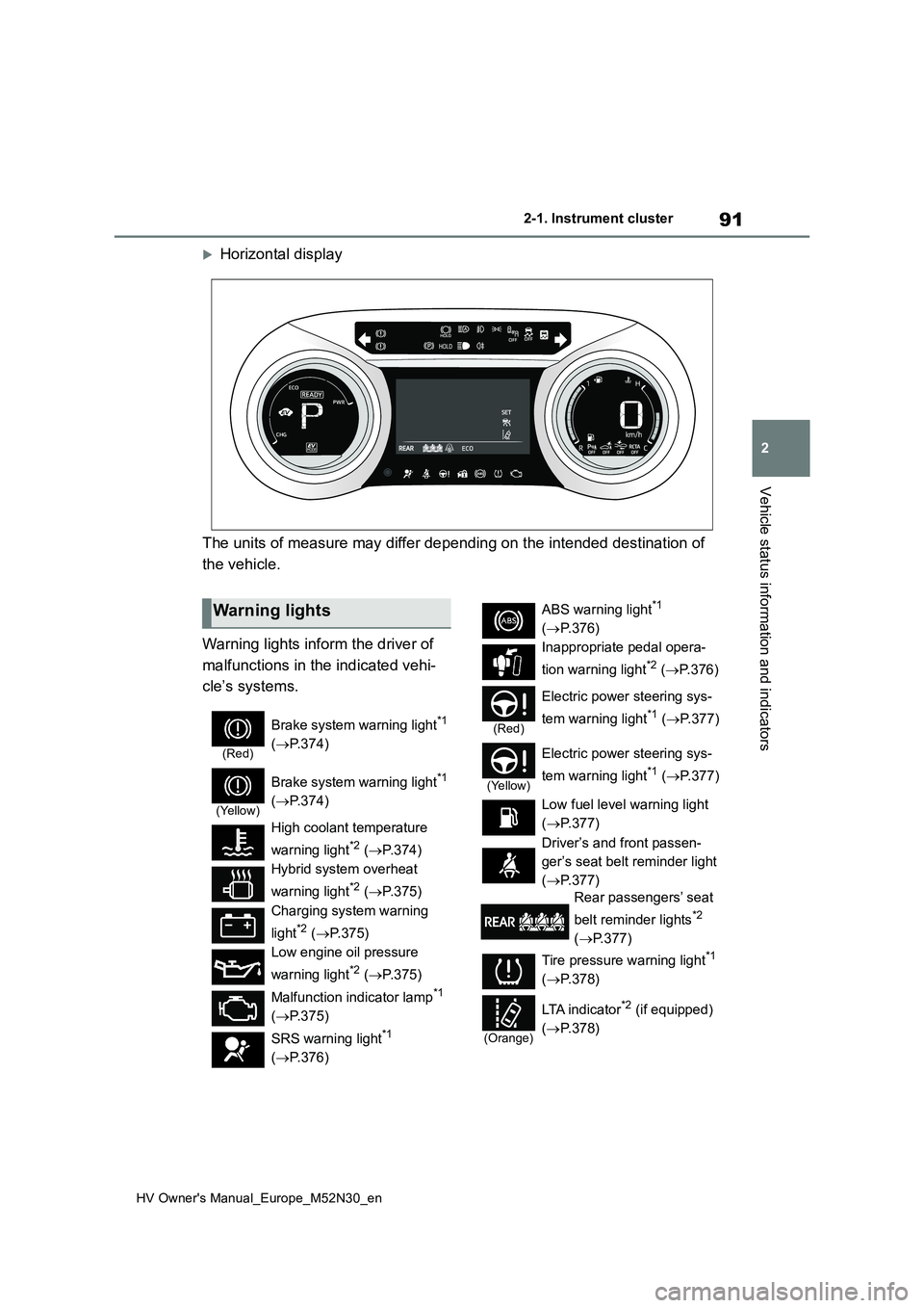
Horizontal display
The units of measure may differ depending on the intended desti nation of
the vehicle.
Warning lights inform the driver of
malfunctions in the indicated vehi-
cle’s systems.
Warning lights
(Red)
Brake system warning light*1
( P.374)
(Yellow)
Brake system warning light*1
( P.374)
High coolant temperature
warning light*2 ( P.374)
Hybrid system overheat
warning light*2 ( P.375)
Charging system warning
light*2 ( P.375)
Low engine oil pressure
warning light*2 ( P.375)
Malfunction indicator lamp*1
( P.375)
SRS warning light*1
( P.376)
ABS warning light*1
( P.376)
Inappropriate pedal opera-
tion warning light*2 ( P. 3 7 6 )
(Red)
Electric power steering sys-
tem warning light*1 ( P.377)
(Yellow)
Electric power steering sys-
tem warning light*1 ( P.377)
Low fuel level warning light
( P.377)
Driver’s and front passen-
ger’s seat belt reminder light
( P.377)
Rear passengers’ seat
belt reminder lights*2
( P.377)
Tire pressure warning light*1
( P.378)
(Orange)
LTA i n d i c a t o r*2 (if equipped)
( P.378)