light VAUXHALL ANTARA 2014 User Guide
[x] Cancel search | Manufacturer: VAUXHALL, Model Year: 2014, Model line: ANTARA, Model: VAUXHALL ANTARA 2014Pages: 217, PDF Size: 5.94 MB
Page 33 of 217

Keys, doors and windows31Heated rear window
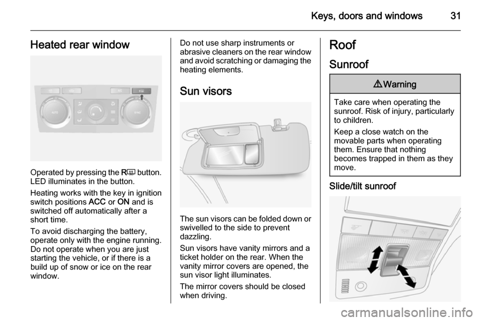
Operated by pressing the RÜ button.
LED illuminates in the button.
Heating works with the key in ignition
switch positions ACC or ON and is
switched off automatically after a
short time.
To avoid discharging the battery, operate only with the engine running. Do not operate when you are juststarting the vehicle, or if there is a
build up of snow or ice on the rear
window.
Do not use sharp instruments or abrasive cleaners on the rear window
and avoid scratching or damaging the
heating elements.
Sun visors
The sun visors can be folded down or swivelled to the side to prevent
dazzling.
Sun visors have vanity mirrors and a
ticket holder on the rear. When the
vanity mirror covers are opened, the
sun visor light illuminates.
The mirror covers should be closed
when driving.
Roof
Sunroof9 Warning
Take care when operating the
sunroof. Risk of injury, particularly to children.
Keep a close watch on the
movable parts when operating
them. Ensure that nothing
becomes trapped in them as they
move.
Slide/tilt sunroof
Page 36 of 217

34Seats, restraints
Stow head restraints securely in load
compartment.
Active head restraintsIn the event of a rear-end impact, the
active head restraints automatically
tilt forwards. Thus the head is
supported so that the risk of whiplash injury is reduced.
Notice
Do not attach objects or components
that are not approved for your
vehicle to the head restraints. These
affect the protective effect of the
head restraints and can be propelled through the vehicle in an
uncontrolled manner if the driver
brakes hard or an accident occurs.
Notice
Approved accessories may only be
attached if the seat is not in use.Front seats
Seat position9 Warning
Only drive with the seat correctly
adjusted.
■ Sit with buttocks as far back against
the backrest as possible. Adjust the distance between the seat and the
pedals so that legs are slightly
angled when pressing the pedals.
Slide the front passenger seat as
far back as possible.
■ Sit with shoulders as far back against the backrest as possible.
Set the backrest rake so that it is possible to easily reach the
steering wheel with arms slightly bent. Maintain contact between
shoulders and the backrest when
turning the steering wheel. Do not
angle the backrest too far back. We recommend a maximum rake of
approximately 25°.
■ Adjust the steering wheel 3 72.
■ Set seat height high enough to have a clear field of vision on allsides and of all display instruments.
There should be at least one hand
of clearance between head and the
roof frame. Your thighs should rest
lightly on the seat without pressing
into it.
■ Adjust the head restraint 3 33.
■ Adjust the height of the seat belt 3 41.
■ Adjust the lumbar support so that it
supports the natural shape of the
spine.
Page 50 of 217

48Seats, restraintsCurtain airbag system
The curtain airbag system consists of an airbag in the roof frame on each
side. This can be identified by the
word AIRBAG on the roof pillars.
The curtain airbag system is triggered in the event of a side-on impact of a
certain severity. The ignition must be
switched on.
The inflated airbags cushion the
impact, thereby considerably
reducing the risk of injury to the head in the event of a side-on impact.
9 Warning
Keep the area in which the airbag
inflates clear of obstructions.
The hooks on the handles in the
roof frame are only suitable for
hanging up light articles of
clothing, without coat hangers. Do not keep any items in these
clothes.
Airbag deactivation
The front passenger airbag system
must be deactivated if a child restraint system is to be fitted on this seat. The
belt pretensioners and all driver
airbag systems will remain active.The front passenger airbag system
can be deactivated via a key-
operated switch on the right side of the instrument panel.
Page 65 of 217

Storage63
Attach the pedal crank by rotating the
attachment screw on the pedal crank
mount.
Place the wheel recesses such that
the bicycle is more or less horizontal. Here, the distance between the
pedals and the tailgate should be at
least 5 cm.
Both bicycle tyres must be in the
wheel recesses.
Caution
Make sure to pull out the wheel
recesses as far as necessary to have both bicycle tyres placed in
the recesses. Otherwise a
horizontal mounting of the bicycle
is not ensured. Disregard could
lead to damage of the bicycle
wheels caused by hot exhaust
fumes.
Align the bicycle in the longitudinal direction of the vehicle: Slightly
loosen the pedal mount.
Place the bicycle upright using the
rotary lever on the pedal crank
recess.
If the two bicycles obstruct one
another, the relative positions of the
bicycles can be adapted by adjusting
the wheel recesses and the rotary
lever on the pedal crank recess until
the bicycles no longer touch one
another. Make sure there is sufficient
clearance from the vehicle.
Tighten the attachment screw for the
pedal bearing mount to its maximum
point by hand.
Page 69 of 217

Storage67
Raise the release lever and hold. Liftthe system slightly and push it into the
bumper until it engages.
Release lever must return to original
position.9 Warning
If the system cannot be correctly
engaged, please seek the
assistance of a workshop.
Load compartment
Storage compartments in the
load compartment
Located on both sides of the load
compartment floor.
Load compartment cover Do not place any objects on the cover.
Closing the cover
Pull load compartment cover towards rear of vehicle using handle and insert
retainers into brackets on either side
of load compartment.
Opening the cover
Remove load compartment cover
from side brackets. The cover rolls up automatically.
Page 71 of 217

Storage69
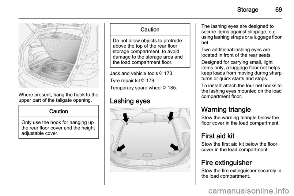
Where present, hang the hook to the
upper part of the tailgate opening.
Caution
Only use the hook for hanging up
the rear floor cover and the height adjustable cover.
Caution
Do not allow objects to protrude
above the top of the rear floor
storage compartment, to avoid
damage to the storage area and
the load compartment floor.
Jack and vehicle tools 3 173.
Tyre repair kit 3 179.
Temporary spare wheel 3 185.
Lashing eyes
The lashing eyes are designed to
secure items against slippage, e.g.
using lashing straps or a luggage floor
net.
Two additional lashing eyes are
located in front of the rear seats.
Designed for carrying small, light
items only, a luggage floor net helps keep loads from moving during sharp turns or quick starts and stops.
To install: attach the four net hooks to
the lashing eyes mounted on the load
compartment floor.
Warning triangle Stow the warning triangle below the
floor cover in the load compartment.
First aid kit Stow the first aid kit below the floor
cover in the load compartment.
Fire extinguisher
Stow the fire extinguisher securely in
the load compartment.
Page 74 of 217

72Instruments and controlsInstruments and
controlsControls ....................................... 72
Warning lights, gauges and indi‐
cators ........................................... 79
Information displays .....................91
Vehicle messages ........................ 98
Trip computer ............................. 100Controls
Steering wheel adjustment
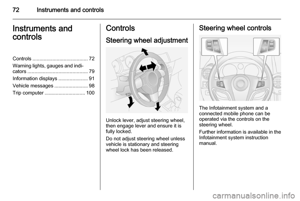
Unlock lever, adjust steering wheel,
then engage lever and ensure it is fully locked.
Do not adjust steering wheel unless
vehicle is stationary and steering
wheel lock has been released.
Steering wheel controls
The Infotainment system and a
connected mobile phone can be
operated via the controls on the
steering wheel.
Further information is available in the
Infotainment system instruction
manual.
Page 76 of 217

74Instruments and controls
In this mode, wiping frequency is alsoaffected by vehicle speed. As vehicle
speed increases, wiping will become
more frequent.
Automatic wiping with rain sensor$=automatic wiping with rain
sensor
The rain sensor detects the amount of water on the windscreen and
automatically regulates the frequency
of the windscreen wiper.
The wiper operates for one cycle to
check the system when the key is
turned to ignition switch position
ACC .
To turn wiper off, move lever to
position §.
Keep the rain sensor area clean by
activating the windscreen washer
system.
Windscreen and headlight
washer
Pull lever. Washer fluid is sprayed
onto the windscreen.
If the lever is held longer, the wiper
operates for two cycles after the lever has been released and once more
after a 3 second delay.
If the headlights are on, washer fluid
is also sprayed onto the headlights.
The headlight washer system can
only be operated again after a short
delay. If washer fluid level is low then
this delay is increased.
Page 77 of 217

Instruments and controls75
Control indicator G illuminates in the
instrument cluster when the washer
fluid level is low.
Wiper activated lighting
With light switch in the AUTO
position, when the windscreen wiper
is operated for 8 cycles or more the
exterior lights illuminate
automatically.
Rear window wiper/washerMove lever to activate the rear
window wiper:Push lever=wiper onPull lever=wiper off
To activate rear window washer
system, press and hold button on end
of lever. Washer fluid is sprayed onto rear window and the wiper wipes a
few times when the button is
released.
Do not use if the windscreen is frozen.
Switch off in car washes.
Outside temperature
A drop in temperature is indicated
immediately and a rise in temperature
after a time delay.
If outside temperature drops to 3 °C, the symbol : illuminates in the
Board-Info-Display as a warning for
icy road conditions. : remains
illuminated until outside temperature
reaches at least 5 °C.
In vehicles with Graphic-Info-Display
or Colour-Info-Display, a message
appears on the display as a warning for icy road conditions. There is no
message below -5 °C.
Page 81 of 217

Instruments and controls79Warning lights, gauges
and indicators
Instrument cluster
In some versions, the needles of the
instruments briefly rotate to the end
position when the ignition is switched on.
Speedometer
Indicates vehicle speed.
Odometer
The odometer display is located in the centre of the instrument cluster.
The bottom line displays the recordeddistance in miles.
Trip odometer The top line displays the recorded
distance since the last reset.
There are two independent trip
odometers. Press the trip odometer
button once to toggle between
Trip A and Trip B.
To reset, press and hold the trip
odometer button for a few seconds
with the ignition on.
Tachometer
Displays the engine speed.
Drive in a low engine speed range for each gear as much as possible.
Caution
If the needle is in the red warning
zone, the maximum permitted
engine speed is exceeded. Engine at risk.