engine VAUXHALL ANTARA 2014 Owner's Manual
[x] Cancel search | Manufacturer: VAUXHALL, Model Year: 2014, Model line: ANTARA, Model: VAUXHALL ANTARA 2014Pages: 217, PDF Size: 5.94 MB
Page 5 of 217

Introduction3Vehicle specific data
Please enter your vehicle's data on
the previous page to keep it easily
accessible. This information is
available in the sections "Service and maintenance" and "Technical data"
as well as on the identification plate.
Introduction
Your vehicle is a designed
combination of advanced technology, safety, environmental friendliness
and economy.
This Owner's Manual provides you
with all the necessary information to
enable you to drive your vehicle
safely and efficiently.
Make sure your passengers are
aware of the possible risk of accident
and injury which may result from
improper use of the vehicle.
You must always comply with the
specific laws and regulations of the
country that you are in. These laws
may differ from the information in this Owner's Manual.When this Owner's Manual refers to aworkshop visit, we recommend your
Vauxhall Authorised Repairer.
All Vauxhall Authorised Repairers
provide first-class service at
reasonable prices. Experienced
mechanics trained by Vauxhall work
according to specific Vauxhall
instructions.
The customer literature pack should
always be kept ready to hand in the
vehicle.
Using this manual ■ This manual describes all options and features available for this
model. Certain descriptions,
including those for display and
menu functions, may not apply to
your vehicle due to model variant,
country specifications, special
equipment or accessories.
■ The "In brief" section will give you an initial overview.
■ The table of contents at the beginning of this manual and withineach section shows where the
information is located.■ The index will enable you to search
for specific information.
■ This Owner's Manual depicts left- hand drive vehicles. Operation is
similar for right-hand drive vehicles.
■ The Owner's Manual uses the factory engine designations. The
corresponding sales designations
can be found in the section
"Technical data".
■ Directional data, e.g. left or right, or
front or back, always relate to the
direction of travel.
■ The vehicle display screens may not support your specific language.
■ Display messages and interior labelling are written in bold letters.
Danger, Warnings and
Cautions9 Danger
Text marked 9 Danger provides
information on risk of fatal injury.
Disregarding this information may
endanger life.
Page 18 of 217
![VAUXHALL ANTARA 2014 Owners Manual 16In brief
Automatic transmissionP=parkR=reverseN=neutralD=drive
Manual mode: move selector lever
from D to the left.
<=higher gear]=lower gear
The selector lever can only be moved
out of P when the VAUXHALL ANTARA 2014 Owners Manual 16In brief
Automatic transmissionP=parkR=reverseN=neutralD=drive
Manual mode: move selector lever
from D to the left.
<=higher gear]=lower gear
The selector lever can only be moved
out of P when the](/img/38/19316/w960_19316-17.png)
16In brief
Automatic transmissionP=parkR=reverseN=neutralD=drive
Manual mode: move selector lever
from D to the left.
<=higher gear]=lower gear
The selector lever can only be moved
out of P when the ignition is on and
the foot brake is applied. To engage
P or R, push the release button.
Automatic transmission 3 128.
Starting off
Check before starting off ■ Tyre pressure and condition 3 176,
3 207.
■ Engine oil level and fluid levels 3 152.
■ All windows, mirrors, exterior lighting and number plates are free
from dirt, snow and ice and are
operational.
■ Proper position of mirrors, seats, and seat belts 3 27, 3 34,
3 41.
■ Brake function at low speed, particularly if the brakes are wet.Starting the engine
■ Turn key to position ACC
■ move the steering wheel slightly to release the steering wheel lock
■ manual transmission in neutral
■ operate clutch and brake pedals ■ automatic transmission in P or N
■ do not accelerate
■ diesel engines: turn key to ON for
preheating and wait until control
indicator ! extinguishes
■ turn key to START and release
Starting the engine 3 123.
Page 19 of 217
In brief17
Stop-start system
If the vehicle is at a low speed or at astandstill and certain conditions are
fulfilled, activate an Autostop as
follows:
■ Depress the clutch pedal
■ shift the selector lever to N
■ release the clutch pedal
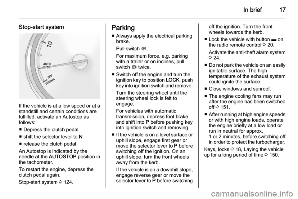
An Autostop is indicated by the
needle at the AUTOSTOP position in
the tachometer.
To restart the engine, depress the
clutch pedal again.
Stop-start system 3 124.
Parking
■ Always apply the electrical parking brake.
Pull switch m.
For maximum force, e.g. parking with a trailer or on inclines, pull
switch m twice.
■ Switch off the engine and turn the ignition key to position LOCK, push
key into ignition switch and remove.
Turn the steering wheel until the
steering wheel lock is felt to
engage.
For vehicles with automatic
transmission, depress foot brake
and shift into P before pushing key
into ignition switch and removing.
■ If the vehicle is on a level surface or
uphill slope, engage first gear or
move the selector lever to P before
switching off the ignition. On an
uphill slope, turn the front wheels
away from the kerb.
If the vehicle is on a downhill slope,
engage reverse gear or move the
selector lever to P before switchingoff the ignition. Turn the front
wheels towards the kerb.
■ Lock the vehicle with button p on
the radio remote control 3 20.
Activate the anti-theft alarm system
3 24.
■ Do not park the vehicle on an easily
ignitable surface. The high
temperature of the exhaust system
could ignite the surface.
■ Close windows and sunroof.
■ The engine cooling fans may run after the engine has been switched
off 3 151.
■ After running at high engine speeds
or with high engine loads, operate the engine briefly at a low load or
run in neutral for approx.
1 or 2 minutes, before switching off in order to protect the turbocharger.
Keys, locks 3 18, Laying the vehicle
up for a long period of time 3 150.
Page 23 of 217
Keys, doors and windows21
Notice
For safety reasons, the vehicle
cannot be locked or unlocked via the remote control (and the anti-theft
systems will not be activated) if the
key is in the ignition switch.
If the driver's door is not closed
properly, the central locking system
will not work.
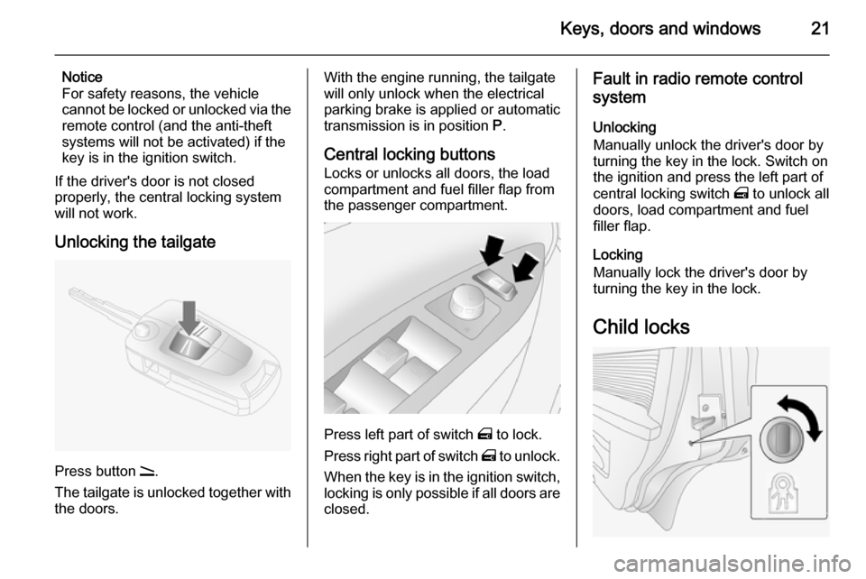
Unlocking the tailgate
Press button q.
The tailgate is unlocked together with the doors.
With the engine running, the tailgate
will only unlock when the electrical
parking brake is applied or automatic
transmission is in position P.
Central locking buttons Locks or unlocks all doors, the load
compartment and fuel filler flap from
the passenger compartment.
Press left part of switch m to lock.
Press right part of switch m to unlock.
When the key is in the ignition switch,
locking is only possible if all doors are closed.
Fault in radio remote control
system
Unlocking
Manually unlock the driver's door by
turning the key in the lock. Switch on
the ignition and press the left part of
central locking switch m to unlock all
doors, load compartment and fuel
filler flap.
Locking
Manually lock the driver's door by
turning the key in the lock.
Child locks
Page 27 of 217
Keys, doors and windows25
Activation without monitoring of
passenger compartment and
vehicle inclination
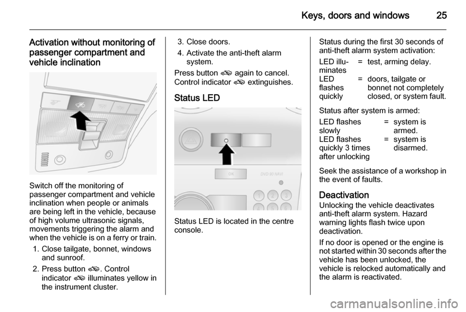
Switch off the monitoring of
passenger compartment and vehicle
inclination when people or animals
are being left in the vehicle, because
of high volume ultrasonic signals,
movements triggering the alarm and
when the vehicle is on a ferry or train.
1. Close tailgate, bonnet, windows and sunroof.
2. Press button o. Control
indicator o illuminates yellow in
the instrument cluster.
3. Close doors.
4. Activate the anti-theft alarm system.
Press button o again to cancel.
Control indicator o extinguishes.
Status LED
Status LED is located in the centre
console.
Status during the first 30 seconds of
anti-theft alarm system activation:LED illu‐
minates=test, arming delay.LED
flashes
quickly=doors, tailgate or
bonnet not completely
closed, or system fault.
Status after system is armed:
LED flashes
slowly=system is
armed.LED flashes
quickly 3 times
after unlocking=system is
disarmed.
Seek the assistance of a workshop in
the event of faults.
Deactivation
Unlocking the vehicle deactivates
anti-theft alarm system. Hazard
warning lights flash twice upon
deactivation.
If no door is opened or the engine is
not started within 30 seconds after the
vehicle has been unlocked, the
vehicle is relocked automatically and
the alarm is reactivated.
Page 28 of 217
26Keys, doors and windows
If the alarm has been triggered, the
hazard warning lights will not flash
upon deactivation.
AlarmWhen triggered, the alarm sounds via
a separate battery-backed power
sounder, and the hazard warning
lights flash simultaneously. The
number and duration of alarm signals are stipulated by legislation.
The alarm can be silenced by
pressing any button of the radio
remote control or manually unlocking
the driver's door with the ignition key.
The anti-theft alarm system is
deactivated at the same time.
If the vehicle's battery is to be
disconnected (e.g. for maintenance work), the alarm siren must be
deactivated as follows: switch the
ignition on then off, then disconnect
the vehicle's battery within
15 seconds.Immobiliser
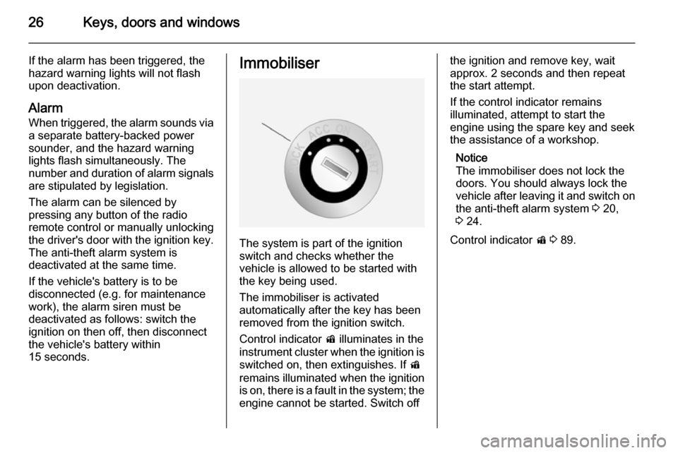
The system is part of the ignition
switch and checks whether the
vehicle is allowed to be started with the key being used.
The immobiliser is activated
automatically after the key has been
removed from the ignition switch.
Control indicator d illuminates in the
instrument cluster when the ignition is switched on, then extinguishes. If d
remains illuminated when the ignition
is on, there is a fault in the system; the
engine cannot be started. Switch off
the ignition and remove key, wait
approx. 2 seconds and then repeat
the start attempt.
If the control indicator remains
illuminated, attempt to start the
engine using the spare key and seek
the assistance of a workshop.
Notice
The immobiliser does not lock the
doors. You should always lock the
vehicle after leaving it and switch on the anti-theft alarm system 3 20,
3 24.
Control indicator d 3 89.
Page 30 of 217
28Keys, doors and windowsHeated mirrors
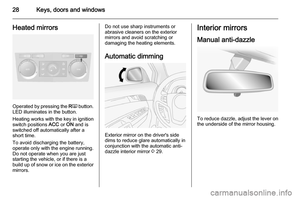
Operated by pressing the RÜ button.
LED illuminates in the button.
Heating works with the key in ignition
switch positions ACC or ON and is
switched off automatically after a
short time.
To avoid discharging the battery, operate only with the engine running. Do not operate when you are juststarting the vehicle, or if there is a
build up of snow or ice on the exterior
mirrors.
Do not use sharp instruments or
abrasive cleaners on the exterior
mirrors and avoid scratching or
damaging the heating elements.
Automatic dimming
Exterior mirror on the driver's side
dims to reduce glare automatically in
conjunction with the automatic anti-
dazzle interior mirror 3 29.
Interior mirrors
Manual anti-dazzle
To reduce dazzle, adjust the lever on the underside of the mirror housing.
Page 33 of 217
Keys, doors and windows31Heated rear window
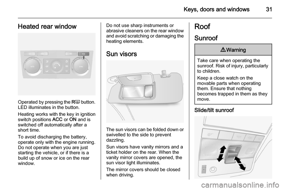
Operated by pressing the RÜ button.
LED illuminates in the button.
Heating works with the key in ignition
switch positions ACC or ON and is
switched off automatically after a
short time.
To avoid discharging the battery, operate only with the engine running. Do not operate when you are juststarting the vehicle, or if there is a
build up of snow or ice on the rear
window.
Do not use sharp instruments or abrasive cleaners on the rear window
and avoid scratching or damaging the
heating elements.
Sun visors
The sun visors can be folded down or swivelled to the side to prevent
dazzling.
Sun visors have vanity mirrors and a
ticket holder on the rear. When the
vanity mirror covers are opened, the
sun visor light illuminates.
The mirror covers should be closed
when driving.
Roof
Sunroof9 Warning
Take care when operating the
sunroof. Risk of injury, particularly to children.
Keep a close watch on the
movable parts when operating
them. Ensure that nothing
becomes trapped in them as they
move.
Slide/tilt sunroof
Page 45 of 217
Seats, restraints43
Front passenger seat beltreminder
When the engine is running, control
indicator k flashes then illuminates if
the passenger seat is occupied and
the seat belt is not engaged.
If vehicle speed exceeds 14 mph, k
will flash for 100 seconds along with
a warning chime, then illuminate until the seat belt is fastened.
Illuminates briefly when ignition is
switched on.
Control indicator X for driver's seat
belt reminder 3 83.
Airbag system
The airbag system consists of a
number of individual systems
depending on the scope of
equipment.
When triggered, the airbags inflate
within milliseconds. They also deflate
so quickly that it is often unnoticeable
during the collision.9 Warning
If handled improperly the airbag
systems can be triggered in an
explosive manner.
Notice
The airbag systems and belt
pretensioner control electronics are
located in the centre console area.
Do not put any magnetic objects in
this area.
Do not stick anything on the airbag
covers and do not cover them with
other materials.
Each airbag is triggered only once.
Have deployed airbags replaced by
a workshop. Furthermore, it might be necessary to have the steering
wheel, the instrument panel, parts of
the panelling, the door seals,
handles and the seats replaced.
Do not make any modifications to
the airbag system as this will
invalidate the vehicle type approval.
When the airbags inflate, escaping
hot gases may cause burns.
Control indicator v for airbag systems
3 83.
Child restraint systems on front passenger seat with airbag
systems Warning according to ECE R94.02:
Page 80 of 217
78Instruments and controls
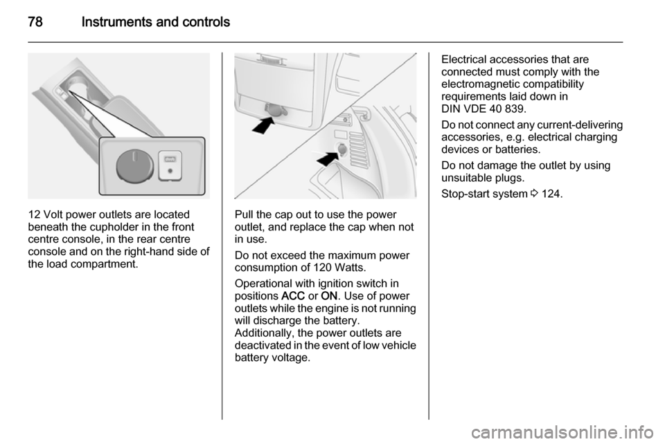
12 Volt power outlets are located
beneath the cupholder in the front
centre console, in the rear centre
console and on the right-hand side of
the load compartment.Pull the cap out to use the power
outlet, and replace the cap when not in use.
Do not exceed the maximum power
consumption of 120 Watts.
Operational with ignition switch in
positions ACC or ON . Use of power
outlets while the engine is not running will discharge the battery.
Additionally, the power outlets are
deactivated in the event of low vehicle
battery voltage.
Electrical accessories that are
connected must comply with the
electromagnetic compatibility
requirements laid down in
DIN VDE 40 839.
Do not connect any current-delivering accessories, e.g. electrical charging
devices or batteries.
Do not damage the outlet by using
unsuitable plugs.
Stop-start system 3 124.