VOLKSWAGEN CORRADO 1990 Repair Manual
Manufacturer: VOLKSWAGEN, Model Year: 1990, Model line: CORRADO, Model: VOLKSWAGEN CORRADO 1990Pages: 906, PDF Size: 6.56 MB
Page 581 of 906

HEATER SYSTEM
Article Text
1990 Volkswagen Corrado
For Volkswagen Technical Site: http://vw.belcom.ru
Copyright © 1998 Mitchell Repair Information Company, LLC
Thursday, March 23, 2000 09:45PM
ARTICLE BEGINNING
1990 HEATER SYSTEMS
Volkswagen
Cabriolet, Corrado, Fox, Golf GL, GTI, Jetta,
Jetta GLi, Vanagon
WARNING: To avoid accidental air bag deployment, see AIR BAG
DEACTIVATION SERVICING PRECAUTIONS in this article.
DESCRIPTION
The heater is a water-valve type that combines heating,
defrosting and ventilation into one unit. Controls include fan control
knob and air distribution and temperature control levers. Blower fan
provides 3 speeds.
NOTE: Vanagon heater system information is not available from
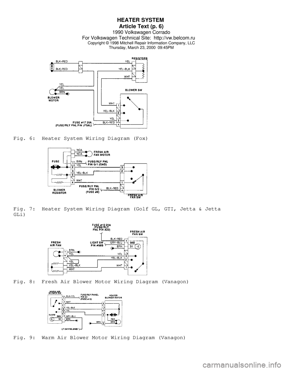
manufacturer. For wiring diagram information, see WIRING
DIAGRAMS at end of this article.
OPERATION
When air distribution lever (upper lever) is in the center
stop position and lower temperature control lever is to the far left,
no air enters vehicle. As air distribution lever is moved to the left,
air is directed to floor vents. As distribution lever is moved to the
right, air is directed to defroster vents.
As heater lever (lower lever) is moved to the right, heater
turns on and heat output is increased. As the fan control knob is
turned to the right, the fan turns on and can be switched across its 3
speeds.
AIR BAG DEACTIVATION SERVICING PRECAUTIONS
WARNING: Some models are equipped with driver's side air bag
restraint system. Air bag-equipped vehicles have AIRBAG
stamped on the steering wheel horn pad. Air bag system
capacitor maintains a voltage charge sufficient to cause air
bag deployment for up to 20 MINUTES after ignition switch is
turned off and battery is disconnected.
DISABLING SYSTEM
Ensure ignition switch is OFF. Disconnect negative battery
cable and insulate terminal. Wait at least 20 MINUTES before
proceeding with repairs.
SYSTEM FUNCTIONAL CHECK
Page 582 of 906
HEATER SYSTEM
Article Text (p. 2)
1990 Volkswagen Corrado
For Volkswagen Technical Site: http://vw.belcom.ru
Copyright © 1998 Mitchell Repair Information Company, LLC
Thursday, March 23, 2000 09:45PM
When all service work is completed, reconnect negative
battery cable. Turn ignition on. Ensure the left turn indicator light
comes on for about 5 seconds and then goes out. If light does not come
on for about 5 seconds and then go out, air bag system needs to be
serviced.
TEMPERATURE CONTROL LEVER ADJUSTMENTS
Move temperature control lever to extreme left position.
Place heater control valve lever in closed position. Secure cable with
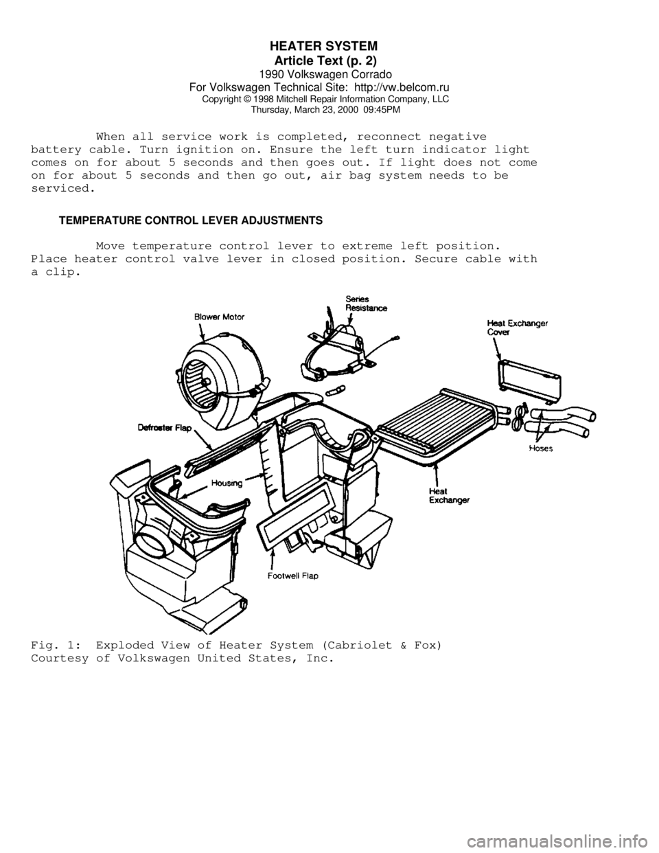
a clip.Fig. 1: Exploded View of Heater System (Cabriolet & Fox)
Courtesy of Volkswagen United States, Inc.
Page 583 of 906
HEATER SYSTEM
Article Text (p. 3)
1990 Volkswagen Corrado
For Volkswagen Technical Site: http://vw.belcom.ru
Copyright © 1998 Mitchell Repair Information Company, LLC
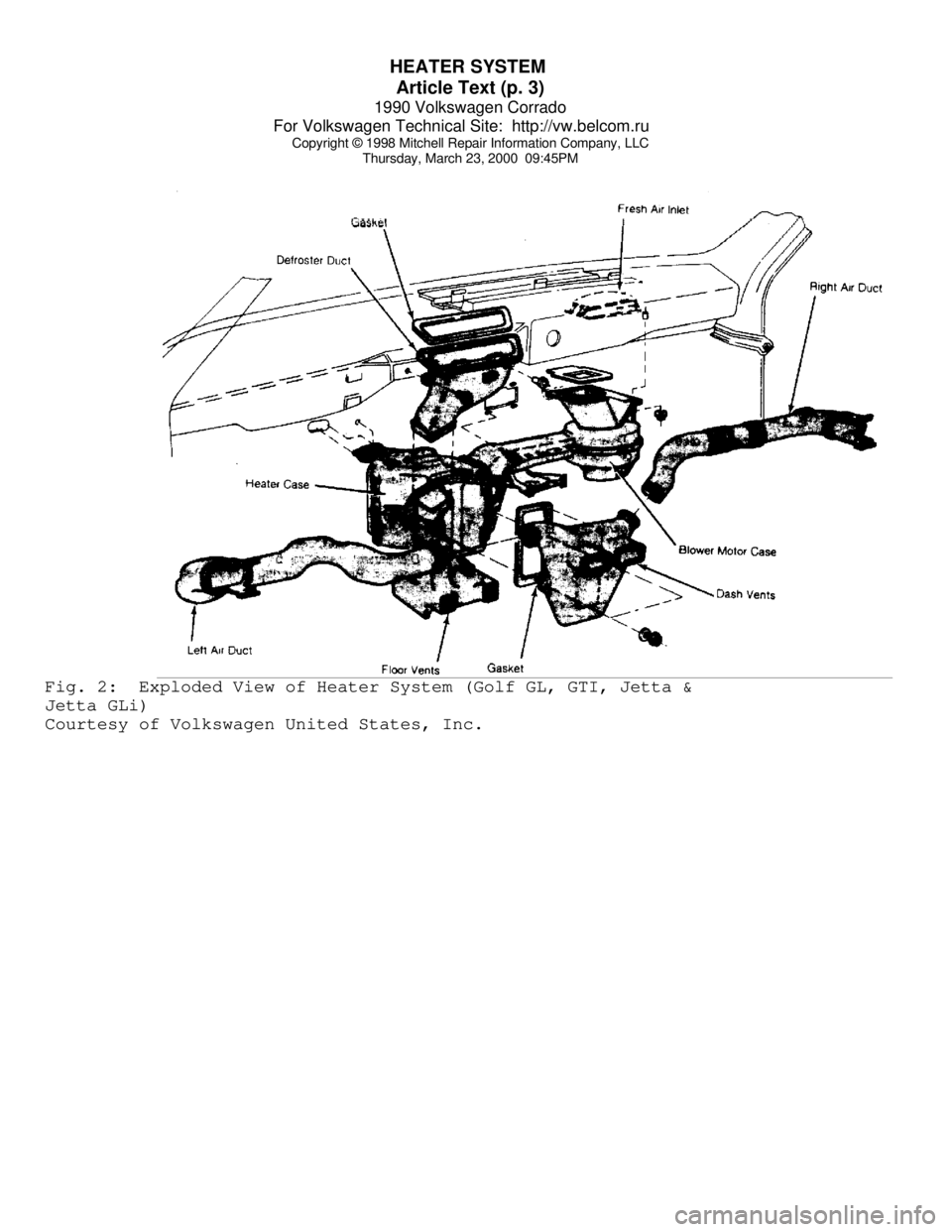
Thursday, March 23, 2000 09:45PMFig. 2: Exploded View of Heater System (Golf GL, GTI, Jetta &
Jetta GLi)
Courtesy of Volkswagen United States, Inc.
Page 584 of 906
HEATER SYSTEM
Article Text (p. 4)
1990 Volkswagen Corrado
For Volkswagen Technical Site: http://vw.belcom.ru
Copyright © 1998 Mitchell Repair Information Company, LLC
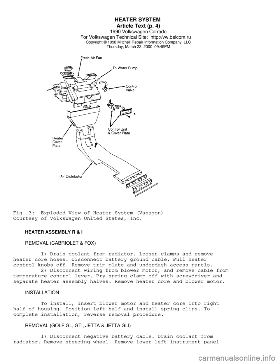
Thursday, March 23, 2000 09:45PMFig. 3: Exploded View of Heater System (Vanagon)
Courtesy of Volkswagen United States, Inc.
HEATER ASSEMBLY R & I
REMOVAL (CABRIOLET & FOX)
1) Drain coolant from radiator. Loosen clamps and remove
heater core hoses. Disconnect battery ground cable. Pull heater
control knobs off. Remove trim plate and underdash access panels.
2) Disconnect wiring from blower motor, and remove cable from
temperature control lever. Pry spring clamp off with screwdriver and
separate heater assembly halves. Remove heater core and blower motor.
INSTALLATION
To install, insert blower motor and heater core into right
half of housing. Position left half and install spring clips. To
complete installation, reverse removal procedure.
REMOVAL (GOLF GL, GTI, JETTA & JETTA GLI)
1) Disconnect negative battery cable. Drain coolant from
radiator. Remove steering wheel. Remove lower left instrument panel
Page 585 of 906
HEATER SYSTEM
Article Text (p. 5)
1990 Volkswagen Corrado
For Volkswagen Technical Site: http://vw.belcom.ru
Copyright © 1998 Mitchell Repair Information Company, LLC
Thursday, March 23, 2000 09:45PM
retaining screws. Remove lower left instrument panel. Remove lower
right instrument panel tray retaining screws.
2) Remove lower right instrument panel. Remove gearshift
lever knob. Remove gearshift lever boot. Remove center console
retaining screws. Slide center console rearward. Disconnect electrical
connectors attached to center console. Remove center console.
3) Remove temperature control knobs. Remove trim plate.
Remove radio. Remove switches from instrument panel. Remove instrument
panel trim plate retaining screws. Remove instrument panel trim plate.
Remove instrument cluster retaining screws. Remove instrument cluster.
4) Disconnect speedometer cable, electrical connectors and
vacuum hoses from instrument cluster. Remove speaker grilles. Remove
air outlet grilles from housings. Remove housing retaining screws.
Remove air outlet housings. Remove instrument panel mounting nuts and
screws.
5) Remove instrument panel. Disconnect heater hoses from
heater core. Remove heater assembly mounting bolts and nuts. Remove
all attaching ducts. Disconnect cables from heater assembly. Remove
heater assembly.
INSTALLATION
Reverse removal procedure for installation. Fill radiator
with coolant and start engine. Ensure heater control is in warm
position to purge air from heater core.
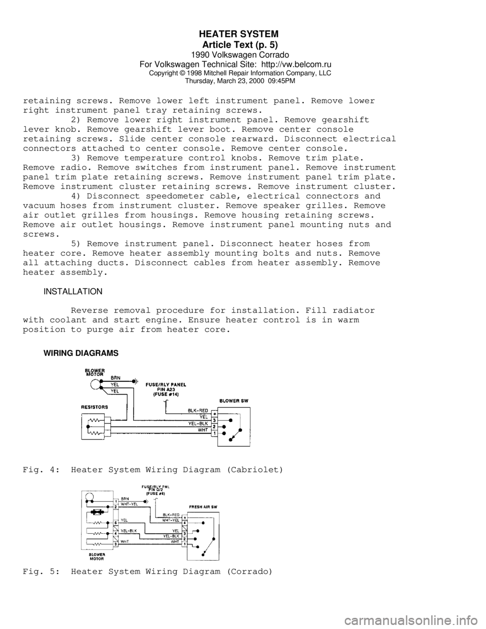
WIRING DIAGRAMSFig. 4: Heater System Wiring Diagram (Cabriolet)Fig. 5: Heater System Wiring Diagram (Corrado)
Page 586 of 906
HEATER SYSTEM
Article Text (p. 6)
1990 Volkswagen Corrado
For Volkswagen Technical Site: http://vw.belcom.ru
Copyright © 1998 Mitchell Repair Information Company, LLC
Thursday, March 23, 2000 09:45PMFig. 6: Heater System Wiring Diagram (Fox)Fig. 7: Heater System Wiring Diagram (Golf GL, GTI, Jetta & Jetta
GLi)Fig. 8: Fresh Air Blower Motor Wiring Diagram (Vanagon)Fig. 9: Warm Air Blower Motor Wiring Diagram (Vanagon)
Page 587 of 906

HEATER SYSTEM
Article Text (p. 7)
1990 Volkswagen Corrado
For Volkswagen Technical Site: http://vw.belcom.ru
Copyright © 1998 Mitchell Repair Information Company, LLC
Thursday, March 23, 2000 09:45PM
END OF ARTICLE
Page 588 of 906

I - SYSTEM/COMPONENT TESTS
Article Text
1990 Volkswagen Corrado
For Volkswagen Technical Site: http://vw.belcom.ru
Copyright © 1998 Mitchell Repair Information Company, LLC
Thursday, March 23, 2000 09:46PM
ARTICLE BEGINNING
1990 ENGINE PERFORMANCE
Systems & Component Testing
Volkswagen; Cabriolet, Corrado, Fox, Golf GL/GTI,
Jetta, Vanagon
INTRODUCTION
Before testing separate components or systems, perform
procedures in F - BASIC TESTING and H - TESTS W/O CODES articles.
NOTE: Testing individual components does not isolate shorts or
opens. Perform all voltage tests with a Digital
Volt-Ohmmeter (DVOM) with a minimum 10-megohm input
impedance, unless stated otherwise in test procedure. Use
ohmmeter to isolate wiring harness shorts or opens.
AIR INDUCTION SYSTEMS (SUPERCHARGER)
BOOST PRESSURE
1) Before checking supercharger boost pressure, ensure engine
idle speed is correct. See D - ADJUSTMENTS article. Ensure engine oil
temperature is 176øF (80øC). Check knock sensor operation. See KNOCK
SENSOR under IDLE CONTROL SYSTEM in this article.
2) Connect Pressure Gauge (VW1397) or equivalent to the
pressure regulator hose using adapter "T". Open pressure gauge check
valve to position "A" and start engine.
3) Remove harness connector from CO potentiometer and Blue
connector from temperature sensor (in front flange on cylinder head).
Accelerate to full throttle. Engine speed must increase periodically
then drop (surge). Watch pressure gauge, boost pressure must reach 8.7
psi (0.6 kg/cm
ý). If boost does not reach specification, check for
leaks in air system and correct by-pass valve setting. Check
supercharger.
COMPUTERIZED ENGINE CONTROLS
NOTE: For fuel system used on model being tested, see FUEL SYSTEM
APPLICATION table.
FUEL SYSTEM APPLICATION
ÄÄÄÄÄÄÄÄÄÄÄÄÄÄÄÄÄÄÄÄÄÄÄÄÄÄÄÄÄÄÄÄÄÄÄÄÄÄÄÄÄÄÄÄÄÄÄÄÄÄÄÄÄÄÄÄÄÄÄÄÄÄÄÄÄÄÄÄÄÄApplication Fuel System
Cabriolet, Corrado, Golf GL/GTI,
Jetta & Vanagon .................................. AFC-Digifant II
Fox .......................................................... CIS-E
Jetta GLi ............................................. CIS-Motronic
Page 589 of 906

I - SYSTEM/COMPONENT TESTS
Article Text (p. 2)
1990 Volkswagen Corrado
For Volkswagen Technical Site: http://vw.belcom.ru
Copyright © 1998 Mitchell Repair Information Company, LLC
Thursday, March 23, 2000 09:46PMÄÄÄÄÄÄÄÄÄÄÄÄÄÄÄÄÄÄÄÄÄÄÄÄÄÄÄÄÄÄÄÄÄÄÄÄÄÄÄÄÄÄÄÄÄÄÄÄÄÄÄÄÄÄÄÄÄÄÄÄÄÄÄÄÄÄÄÄÄÄ CONTROL UNIT (AFC-DIGIFANT II)
NOTE: Before checking ECU terminal voltages, check all terminals
and connections for looseness or presence of corrosion.
Repair as needed, before continuing.
GROUND CIRCUITS
Using Multimeter (US 1119), check resistance of ground
connections for ECU. Remove ECU connector. Check continuity to ground
on terminals No. 13 and 19. See L - WIRING DIAGRAMS for terminal
identification. Resistance should be zero ohms. If resistance is not
zero ohms, repair open or short in wiring.
POWER CIRCUITS
1) Turn ignition off. Disconnect ECU connector. Using a
voltmeter, turn ignition on and check for battery voltage between ECU
connector terminals No. 13 (negative) and No. 14 (positive). See L -
WIRING DIAGRAMS for terminal identification and wire colors. If
battery voltage is not present, repair wiring as required.
2) Check terminals No. 13 (negative) and No. 1 (positive) for
battery voltage. If battery voltage is not present, check fuse No. 18
on fuse block. If fuse is okay, check wiring from ECU connector to
fuse box for open.
CONTROL UNIT (CIS-E)
GROUND CIRCUITS
Using Multimeter (US 1119), check resistance of ground
circuits for ECU. Remove ECU connector. Check continuity to ground on
terminals No. 2 and No. 9. Resistance should be zero ohms. If
resistance is not zero ohms, repair open or short in wiring.
POWER CIRCUITS
Turn ignition off. Disconnect ECU connector. Using a
voltmeter, turn ignition on and check for battery voltage between ECU
connector terminals No. 2 (negative) and No. 1 (positive). See L -
WIRING DIAGRAMS for terminal identification and wire colors. If
battery voltage is not present, check fuse No. 23 on fuse block. If
fuse is okay, check CIS-E ECU connector to fuse box wiring for open.
CONTROL UNIT (CIS-MOTRONIC)
GROUND CIRCUITS
Using Multimeter (US 1119), check resistance of ground
Page 590 of 906
I - SYSTEM/COMPONENT TESTS
Article Text (p. 3)
1990 Volkswagen Corrado
For Volkswagen Technical Site: http://vw.belcom.ru
Copyright © 1998 Mitchell Repair Information Company, LLC
Thursday, March 23, 2000 09:46PM
circuits to ECU. The ECU engine ground is near ignition distributor.
Remove ECU connector. Check resistance to ground on terminal No. 35.
Resistance should be zero ohms. If resistance is not zero ohms, repair
open or short in wiring.
POWER CIRCUITS
Turn ignition off. Disconnect ECU connector. Using a
voltmeter, check terminals No. 12, 14, 19 and 34 for battery voltage.
If battery voltage is not present. Check fuses No. 15, 18 and 24. If
fuses are okay, check for open in wiring between ECU and fuse box. See
L - WIRING DIAGRAMS for terminal identification and wire colors.
ENGINE SENSORS & SWITCHES
AIRFLOW SENSOR (FOX & JETTA GLI)
1) Start engine to pressurized fuel system. Turn engine off
and remove intake boot from top of airflow sensor. Disconnect coil
secondary wire from coil and jumper to ground.
2) Check sensor play by slowly moving sensor plate through
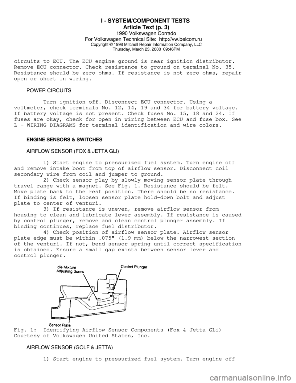
travel range with a magnet. See Fig. 1. Resistance should be felt.
Move plate back to the rest position. There should be no resistance.
If binding is felt, loosen sensor plate hold-down bolt and adjust
plate to center of venturi.
3) If resistance is uneven, remove airflow sensor from
housing to clean and lubricate lever assembly. If resistance is caused
by control plunger, remove and clean control plunger assembly. If
binding continues, replace fuel distributor.
4) Check position of airflow sensor plate. Airflow sensor
plate edge must be within .075" (1.9 mm) below the narrowest section
of the venturi. If not, bend sensor spring until correct specification
is obtained. Ensure a small gap exists between sensor lever and
control plunger.Fig. 1: Identifying Airflow Sensor Components (Fox & Jetta GLi)
Courtesy of Volkswagen United States, Inc.
AIRFLOW SENSOR (GOLF & JETTA)
1) Start engine to pressurized fuel system. Turn engine off