VOLKSWAGEN CORRADO 1990 Repair Manual
Manufacturer: VOLKSWAGEN, Model Year: 1990, Model line: CORRADO, Model: VOLKSWAGEN CORRADO 1990Pages: 906, PDF Size: 6.56 MB
Page 731 of 906
STARTER - BOSCH
Article Text (p. 4)
1990 Volkswagen Corrado
For Volkswagen Technical Site: http://vw.belcom.ru
Copyright © 1998 Mitchell Repair Information Company, LLC
Thursday, March 23, 2000 09:51PM
remove upper starter mounting bolt. Release handbrake (to allow axle
rotation) and raise vehicle on hoist.
2) Disconnect right rear axle from transmission and wire
aside. Cover exposed CV joint with plastic bag to prevent entry of
dirt or other foreign material.
3) Loosen clamp securing cooling hoses to chassis. Wire hoses
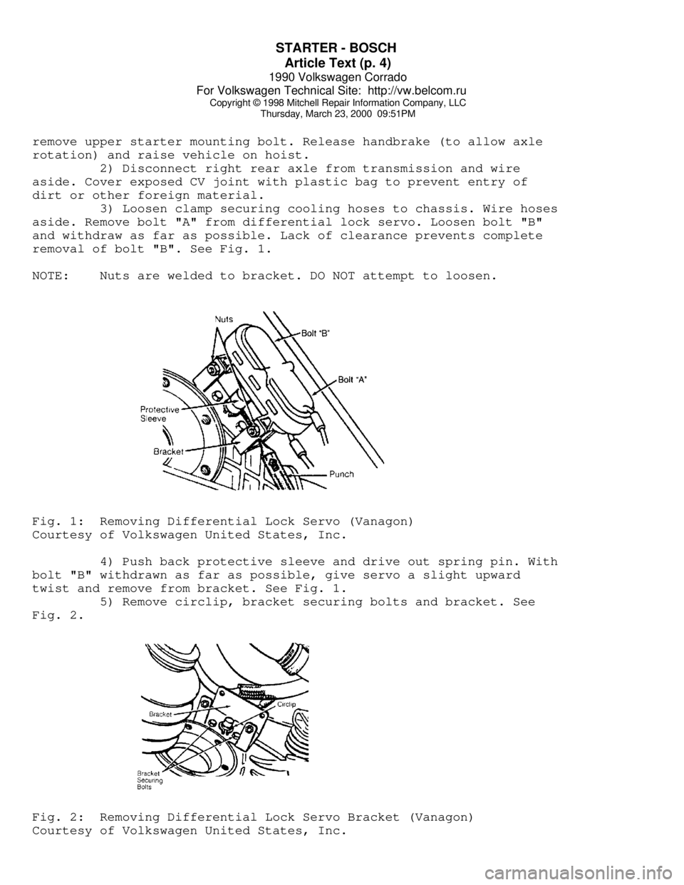
aside. Remove bolt "A" from differential lock servo. Loosen bolt "B"
and withdraw as far as possible. Lack of clearance prevents complete
removal of bolt "B". See Fig. 1.
NOTE: Nuts are welded to bracket. DO NOT attempt to loosen.Fig. 1: Removing Differential Lock Servo (Vanagon)
Courtesy of Volkswagen United States, Inc.
4) Push back protective sleeve and drive out spring pin. With
bolt "B" withdrawn as far as possible, give servo a slight upward
twist and remove from bracket. See Fig. 1.
5) Remove circlip, bracket securing bolts and bracket. See
Fig. 2.Fig. 2: Removing Differential Lock Servo Bracket (Vanagon)
Courtesy of Volkswagen United States, Inc.
Page 732 of 906
STARTER - BOSCH
Article Text (p. 5)
1990 Volkswagen Corrado
For Volkswagen Technical Site: http://vw.belcom.ru
Copyright © 1998 Mitchell Repair Information Company, LLC
Thursday, March 23, 2000 09:51PM
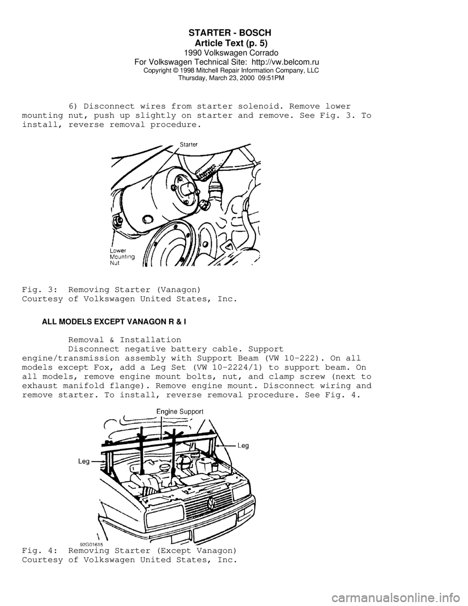
6) Disconnect wires from starter solenoid. Remove lower
mounting nut, push up slightly on starter and remove. See Fig. 3. To
install, reverse removal procedure.Fig. 3: Removing Starter (Vanagon)
Courtesy of Volkswagen United States, Inc.
ALL MODELS EXCEPT VANAGON R & I
Removal & Installation
Disconnect negative battery cable. Support
engine/transmission assembly with Support Beam (VW 10-222). On all
models except Fox, add a Leg Set (VW 10-2224/1) to support beam. On
all models, remove engine mount bolts, nut, and clamp screw (next to
exhaust manifold flange). Remove engine mount. Disconnect wiring and
remove starter. To install, reverse removal procedure. See Fig. 4.Fig. 4: Removing Starter (Except Vanagon)
Courtesy of Volkswagen United States, Inc.
Page 733 of 906
STARTER - BOSCH
Article Text (p. 6)
1990 Volkswagen Corrado
For Volkswagen Technical Site: http://vw.belcom.ru
Copyright © 1998 Mitchell Repair Information Company, LLC
Thursday, March 23, 2000 09:51PM
OVERHAUL
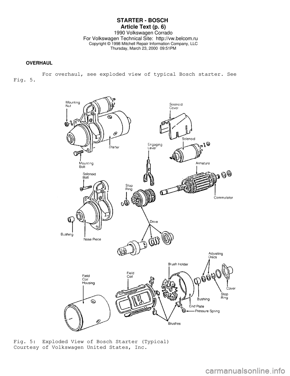
For overhaul, see exploded view of typical Bosch starter. See
Fig. 5.Fig. 5: Exploded View of Bosch Starter (Typical)
Courtesy of Volkswagen United States, Inc.
Page 734 of 906

STARTER - BOSCH
Article Text (p. 7)
1990 Volkswagen Corrado
For Volkswagen Technical Site: http://vw.belcom.ru
Copyright © 1998 Mitchell Repair Information Company, LLC
Thursday, March 23, 2000 09:51PM
STARTER SPECIFICATIONS
STARTER SPECIFICATIONSÄÄÄÄÄÄÄÄÄÄÄÄÄÄÄÄÄÄÄÄÄÄÄÄÄÄÄÄÄÄÄÄÄÄÄÄÄÄÄÄÄÄÄÄÄÄÄÄÄÄÄÄÄÄÄÄApplication Specification
Armature
Runout ............................... .002" (.05mm)
End Play ............................. .002" (.05mm)
Cold Cranking
Test Voltage .................................... 12
Minimum Voltage .................................. 9
Amps ............................................ 90
Minimum RPM ................................... 1500
Solenoid Hold-In
Winding Voltage .................... 4 Volts (Min.)
Solenoid Pull-In
Winding Voltage ................................. 7
Commutator Runout ..................... .0004" (.01mm)
Cranking Voltage ........................ 9 Volts Min.
Starter Current Draw ................... 170 Amps Max.
ÄÄÄÄÄÄÄÄÄÄÄÄÄÄÄÄÄÄÄÄÄÄÄÄÄÄÄÄÄÄÄÄÄÄÄÄÄÄÄÄÄÄÄÄÄÄÄÄÄÄÄÄÄÄÄÄ TORQUE SPECIFICATIONS
TORQUE SPECIFICATIONS
ÄÄÄÄÄÄÄÄÄÄÄÄÄÄÄÄÄÄÄÄÄÄÄÄÄÄÄÄÄÄÄÄÄÄÄÄÄÄÄÄÄÄÄÄÄÄÄÄÄÄÄÄÄÄÄÄÄÄÄÄÄApplication Ft. Lbs. (N.m)
Starter-To-Block Bolts
All Except Vanagon .................... 32.5-44.3 (44-60)
Vanagon ......................................... 21 (28)
Starter-To-Block Bolts (1992)
Cabriolet, Golf, GTI & Jetta
A/T ............................................. 14 (19)
M/T ............................................. 43 (58)
Corrado, Fox & Passat ............................ 44 (60)
INCH LBS. (N.m)
Solenoid Bolts .................................. 96 (10.8)
Through Bolts .................................... 54 (6.1)
ÄÄÄÄÄÄÄÄÄÄÄÄÄÄÄÄÄÄÄÄÄÄÄÄÄÄÄÄÄÄÄÄÄÄÄÄÄÄÄÄÄÄÄÄÄÄÄÄÄÄÄÄÄÄÄÄÄÄÄÄÄEND OF ARTICLE
Page 735 of 906

STEERING COLUMN
Article Text
1990 Volkswagen Corrado
For Volkswagen Technical Site: http://vw.belcom.ru
Copyright © 1998 Mitchell Repair Information Company, LLC
Thursday, March 23, 2000 09:51PM
ARTICLE BEGINNING
1990-92 STEERING
Volkswagen Steering Columns
Cabriolet, Corrado, Fox, Golf, GTI, Jetta, Passat
WARNING: To aviod injury from accidental AIR BAG deployment, read and
carefully follow all WARNINGS and SERVICE PRECAUTIONS.
NOTE: For information on air bag DIAGNOSIS & TESTING or DISPOSAL
PROCEDURES, See appropriate AIR BAG article in the
ACCESSORIES/SAFETY EQUIPMENT Section
DESCRIPTION
Swing-away steering column is held by a clamp and leaf
spring. On impact, the "U" joint shaft pushes steering column against
the leaf spring. The spring allows the column to disengage and swing
away.
CAUTION: Applying excessive pressure or causing impact to mainshaft
during service may cause the column to disengage.
REMOVAL & INSTALLATION
AIR BAG
WARNING: On Cabriolet with Supplemental Restraint System (air bag),
remove air bag from vehicle before working on steering
column. Follow all WARNINGS and SERVICE PRECAUTIONS to
prevent injury from accidental air bag deployment. See AIR
BAG article in the ACCESSORY/SAFETY EQUIPMENT.
Removal & Installation (Cabriolet)
1) Disconnect negative battery cable. Wait at least 20
minutes for air bag capacitor to discharge. Remove 2 Torx screws (No.
30) from back of steering wheel.
2) Carefully tilt air bag down away from steering wheel.
Disconnect electrical wire from back of air bag unit. Remove air bag
unit from vehicle. DO NOT store air bag unit on its vinyl side. Store
air bag unit on its metal housing.
3) To install, reverse removal procedure. Install new Torx
screws to hold air bag unit in steering wheel. Tighten Torx screws to
89 INCH lbs. (10 N.m).
STEERING WHEEL & HORN PAD
Removal & Installation
1) Disconnect negative battery cable. On Corrado and Passat,
lift cover from bottom, then pull cover away from steering wheel. On
Page 736 of 906

STEERING COLUMN
Article Text (p. 2)
1990 Volkswagen Corrado
For Volkswagen Technical Site: http://vw.belcom.ru
Copyright © 1998 Mitchell Repair Information Company, LLC
Thursday, March 23, 2000 09:51PM
Corrado and Passat, spread horn button locating lugs, then separate
contact plates. On other models, pry center cover from steering wheel.
2) Disconnect horn wiring. Ensure steering wheel is in
straight-ahead position. Mark shaft and wheel for reassembly
reference. Remove retaining nut and washer. Pull steering wheel from
shaft. Reverse removal procedure to install.
TURN SIGNAL SWITCH
Removal & Installation
Remove steering wheel. See STEERING WHEEL & HORN PAD. Remove
retaining screws. Unplug harness connector. Remove turn signal switch.
To install, reverse removal procedure.
WINDSHIELD WIPER SWITCH
Removal & Installation
Remove steering wheel. See STEERING WHEEL & HORN PAD. Remove
turn signal switch. See TURN SIGNAL SWITCH. Remove retaining screws.
Unplug harness connector. Remove windshield wiper switch. To install,
reverse removal procedure.
IGNITION SWITCH (ALL BUT CORRADO)
Removal (All But Corrado)
1) Remove steering wheel. See STEERING WHEEL & HORN PAD.
Remove lower cover from steering column. Remove turn signal and
windshield wiper switches. See TURN SIGNAL SWITCH and WINDSHIELD WIPER
SWITCH. Remove lock washer, spring and horn contact ring.
2) Remove bolt retaining steering column tube to steering
column housing. Disconnect wiring from ignition switch. Unlock
steering with ignition key. Remove steering column housing, ignition
lock and upper half of steering column switch cover. Remove retaining
screw and ignition switch.
Installation
To install ignition switch, reverse removal procedure.
Removal (Corrado)
1) Remove steering column and steering column switch. Insert
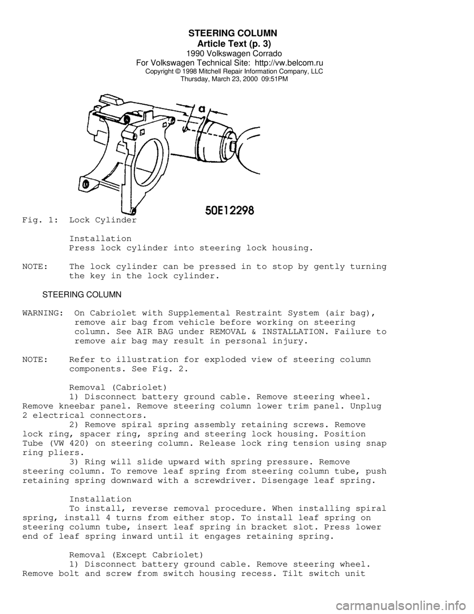
ignition key in ignition lock. Mark dimension "a" in Fig. 1. on line
with key (0.5" (12mm)).
2) Bore hole approximately 0.12" (3mm) in diameter through
steering lock housing until stop spring of lock cylinder is visible;
hole depth is approximately 0.12" (3mm). Compress stop spring with a
punch and pull out lock cylinder with key.
Page 737 of 906
STEERING COLUMN
Article Text (p. 3)
1990 Volkswagen Corrado
For Volkswagen Technical Site: http://vw.belcom.ru
Copyright © 1998 Mitchell Repair Information Company, LLC
Thursday, March 23, 2000 09:51PMFig. 1: Lock Cylinder
Installation
Press lock cylinder into steering lock housing.
NOTE: The lock cylinder can be pressed in to stop by gently turning
the key in the lock cylinder.
STEERING COLUMN
WARNING: On Cabriolet with Supplemental Restraint System (air bag),
remove air bag from vehicle before working on steering
column. See AIR BAG under REMOVAL & INSTALLATION. Failure to
remove air bag may result in personal injury.
NOTE: Refer to illustration for exploded view of steering column
components. See Fig. 2.
Removal (Cabriolet)
1) Disconnect battery ground cable. Remove steering wheel.
Remove kneebar panel. Remove steering column lower trim panel. Unplug
2 electrical connectors.
2) Remove spiral spring assembly retaining screws. Remove
lock ring, spacer ring, spring and steering lock housing. Position
Tube (VW 420) on steering column. Release lock ring tension using snap
ring pliers.
3) Ring will slide upward with spring pressure. Remove
steering column. To remove leaf spring from steering column tube, push
retaining spring downward with a screwdriver. Disengage leaf spring.
Installation
To install, reverse removal procedure. When installing spiral
spring, install 4 turns from either stop. To install leaf spring on
steering column tube, insert leaf spring in bracket slot. Press lower
end of leaf spring inward until it engages retaining spring.
Removal (Except Cabriolet)
1) Disconnect battery ground cable. Remove steering wheel.
Remove bolt and screw from switch housing recess. Tilt switch unit
Page 738 of 906
STEERING COLUMN
Article Text (p. 4)
1990 Volkswagen Corrado
For Volkswagen Technical Site: http://vw.belcom.ru
Copyright © 1998 Mitchell Repair Information Company, LLC
Thursday, March 23, 2000 09:51PM
toward instrument panel. Pry spacer sleeve from column.
2) Pull up combination switch to disconnect wires. Remove
combination switch. Disconnect steering shaft from "U" joint shaft.
Disconnect brake pedal push rod.
3) Disconnect clutch cable from clutch pedal. Using a
screwdriver, push down leaf spring retainer clip to disengage it from
mounting slot.
4) Remove bolts that retain steering column under instrument
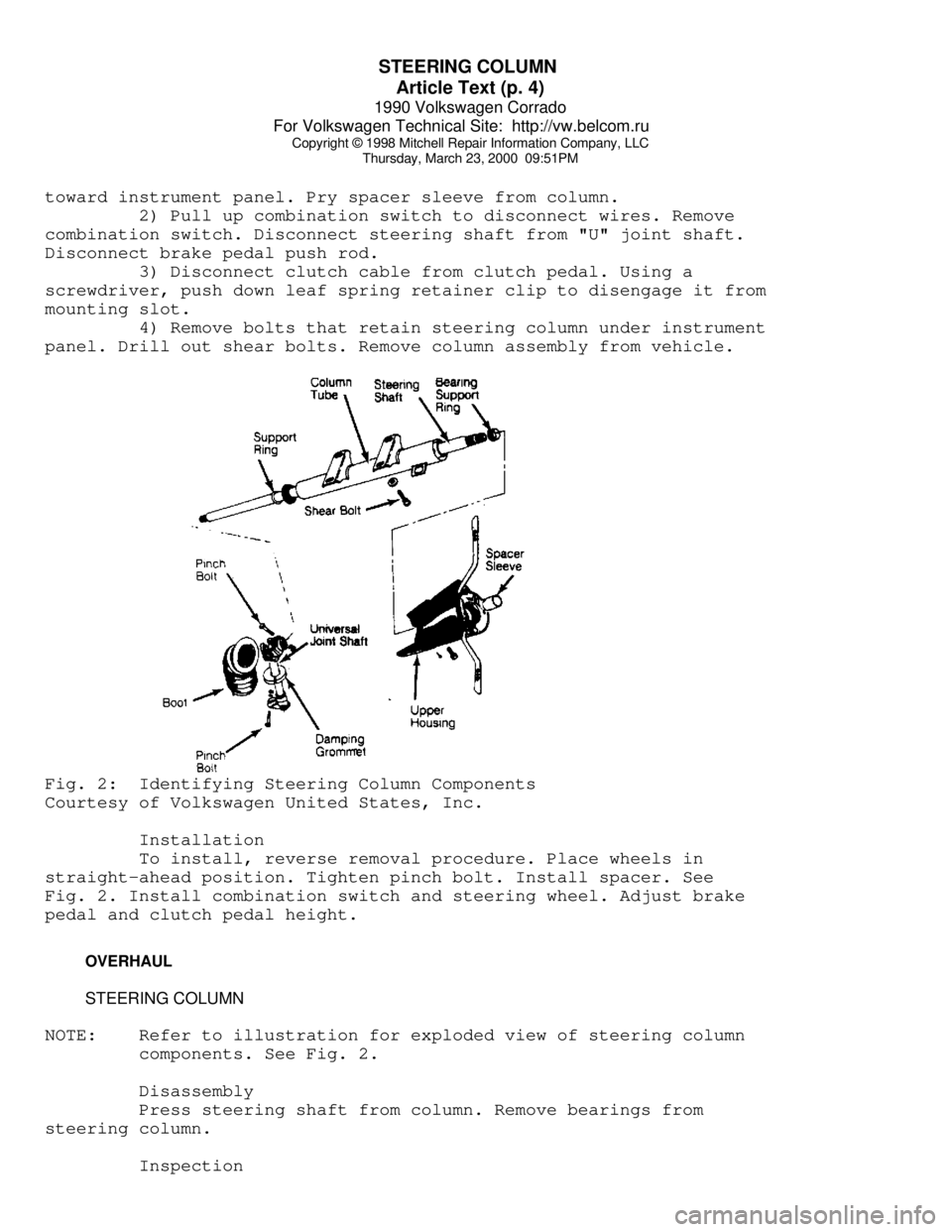
panel. Drill out shear bolts. Remove column assembly from vehicle.Fig. 2: Identifying Steering Column Components
Courtesy of Volkswagen United States, Inc.
Installation
To install, reverse removal procedure. Place wheels in
straight-ahead position. Tighten pinch bolt. Install spacer. See
Fig. 2. Install combination switch and steering wheel. Adjust brake
pedal and clutch pedal height.
OVERHAUL
STEERING COLUMN
NOTE: Refer to illustration for exploded view of steering column
components. See Fig. 2.
Disassembly
Press steering shaft from column. Remove bearings from
steering column.
Inspection
Page 739 of 906

STEERING COLUMN
Article Text (p. 5)
1990 Volkswagen Corrado
For Volkswagen Technical Site: http://vw.belcom.ru
Copyright © 1998 Mitchell Repair Information Company, LLC
Thursday, March 23, 2000 09:51PM
Check upper bracket for damage and upper bearing for smooth
rotation. Check shafts for signs of bending, damaged splines, or
damaged "U" joints. Check column tube for bending or other damage.
Repair or replace components as necessary.
Reassembly
Press in steering shaft and new bearings. DO NOT use more
than 200 lbs. (90 kg) force to press shaft and bearings into column
tube.
"U" JOINT SHAFT
Disassembly
1) Remove pinch bolt that connects lower end of "U" joint
shaft to steering gear pinion shaft. See Fig. 2. Separate manual
gearshift linkage from steering box. Remove steering gear retaining
nuts.
2) Pull box down to separate from lower "U" joint. Remove
rubber boot from lower "U" joint. Remove upper "U" joint pinch bolt.
Pull down joint and remove shaft with "U" joints.
Inspection
Inspect "U" joints for wear or excessive play. If abnormal
wear or play exists, replace as necessary.
Reassembly
1) Fit "U" joint to steering shaft. Align steering shaft
notch with lower "U" joint slot. Install boot and damping grommet. Fit
steering box to frame while guiding pinion shaft into lower "U" joint.
2) Hand-tighten steering gear retaining nuts. Place wheels in
straight-ahead position. Align pinion shaft and "U" joint. Tighten
pinch bolt. Tighten steering gear retaining nuts. Connect gearshift
linkage. Check linkage for smooth operation.
TORQUE SPECIFICATIONS
TORQUE SPECIFICATIONS TABLEÄÄÄÄÄÄÄÄÄÄÄÄÄÄÄÄÄÄÄÄÄÄÄÄÄÄÄÄÄÄÄÄÄÄÄÄÄÄÄÄÄÄÄÄÄÄÄÄÄÄÄÄÄÄÄÄÄÄÄÄÄÄÄÄÄApplication Ft. Lbs. (N.m)
Pinch Bolt ............................................ 22 (30)
Steering Column-To-Instrument Panel
Retaining Bolt ...................................... 15 (20)
Shear Bolt ............................................ (1)
Steering Gear Retaining Nut ........................... 22 (30)
Steering Wheel Nut .................................... 37 (50)
(1) - Tighten until bolt head snaps off.
ÄÄÄÄÄÄÄÄÄÄÄÄÄÄÄÄÄÄÄÄÄÄÄÄÄÄÄÄÄÄÄÄÄÄÄÄÄÄÄÄÄÄÄÄÄÄÄÄÄÄÄÄÄÄÄÄÄÄÄÄÄÄÄÄÄEND OF ARTICLE
Page 740 of 906

STEERING COLUMN SWITCHES
Article Text
1990 Volkswagen Corrado
For Volkswagen Technical Site: http://vw.belcom.ru
Copyright © 1998 Mitchell Repair Information Company, LLC
Thursday, March 23, 2000 09:51PM
ARTICLE BEGINNING
1989-92 SAFETY EQUIPMENT
Steering Column Switches
Cabriolet, Corrado, Fox,
Golf, GTI, Jetta, Passat
WARNING: To avoid injury from accidental air bag deployment, read and
carefully follow all WARNINGS and SERVICE PRECAUTIONS.
NOTE: For information on air bag DIAGNOSIS & TESTING or DISPOSAL
PROCEDURES, see the AIR BAGS article.
SERVICE PRECAUTIONS
Observe these precautions when working with air bag systems:
* DO NOT use computer memory saver tool. Using computer
memory tool will keep air bag system active and may
cause accidental deployment of air bag unit.
* Disable air bag system before servicing any air bag
system or steering column component. See DISABLING &
ACTIVATING AIR BAG SYSTEM.
* Because of critical operating requirements of system,
DO NOT attempt to service any air bag system component.
* Air bag parts should not be left unattended. They
should be installed in vehicle immediately after
obtaining them.
* Air bag components which have been dropped more than 18
inches should not be used.
* Chemical cleaners, oil and grease should not contact
vinyl covering on air bag unit.
* DO NOT place stickers or covers on steering wheel.
* Always disable air bag system before performing
electric welding on vehicle.
* Air bag system can only be tested using Diagnostic
Tester (VAG 1551) and Multimeter (US 1119). Never use
test light on air bag system.
* DO NOT expose air bag unit to temperatures greater than
194øF (90øC).
SYSTEM OPERATION CHECK
Two lights pertaining to air bag system are located directly
above air bag symbol in instrument cluster. See Fig. 1.
Control light is used to indicate readiness of system. This
light, which glows when ignition switch is turned to ON position or
engine is started, will stay on approximately 5-8 seconds while
diagnosis unit in air bag control unit performs an electronic test
cycle of system.