VOLKSWAGEN GOLF 1993 1H / 3.G Owners Manual
Manufacturer: VOLKSWAGEN, Model Year: 1993, Model line: GOLF, Model: VOLKSWAGEN GOLF 1993 1H / 3.GPages: 156, PDF Size: 6.36 MB
Page 121 of 156
Downloaded from www.Manualslib.com manuals search engine ________~D=O~-~IT-VOURSELF
Fuses
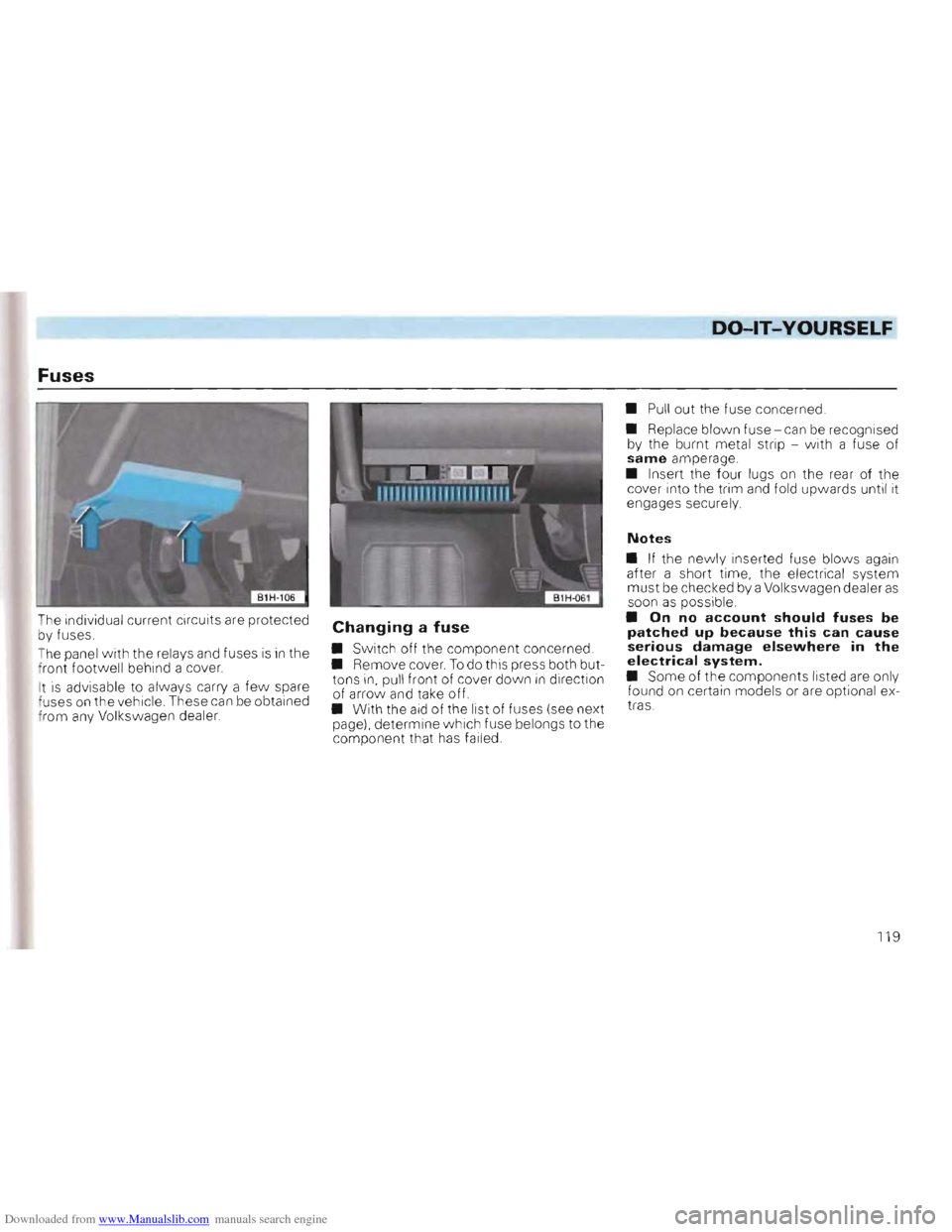
The individual current circuits are protected
b y fuses .
T he panel w ith
the relays and fuses is in the
front footwell behind a cover.
I t
is advisable to always carry a few spare
fuses on the vehicle . These can be obtained
f rom any Volkswagen dealer.
Changing a fuse
• Switch off the component concerned.
• Remove cover. To do this press both but
tons in, pull front of cover down in direction
of arrow and take off.
•
With the aid of the list of fuses (see next
page). determine w hich fuse belongs to the component that has failed. •
Pull out the fuse concerned.
• Replace
blown fuse -can be recognised
by the burnt metal strip -w ith a fuse of same amperage .
• Insert the four lugs on
the rear of the cover into the trim and fold upwards until it
engages securely.
Notes
• If the newly inserted fuse blows again after a short time, the electrical system must be checked by a Volkswagen dealer as soon as possible.
• On no account should fuses be patched up because this can cause serious damage elsewhere in the electrical system.
• Some of the components listed are only
found on certain models or are optional ex
tras.
119
Page 122 of 156
Downloaded from www.Manualslib.com manuals search engine DO-lT-YOURSELF
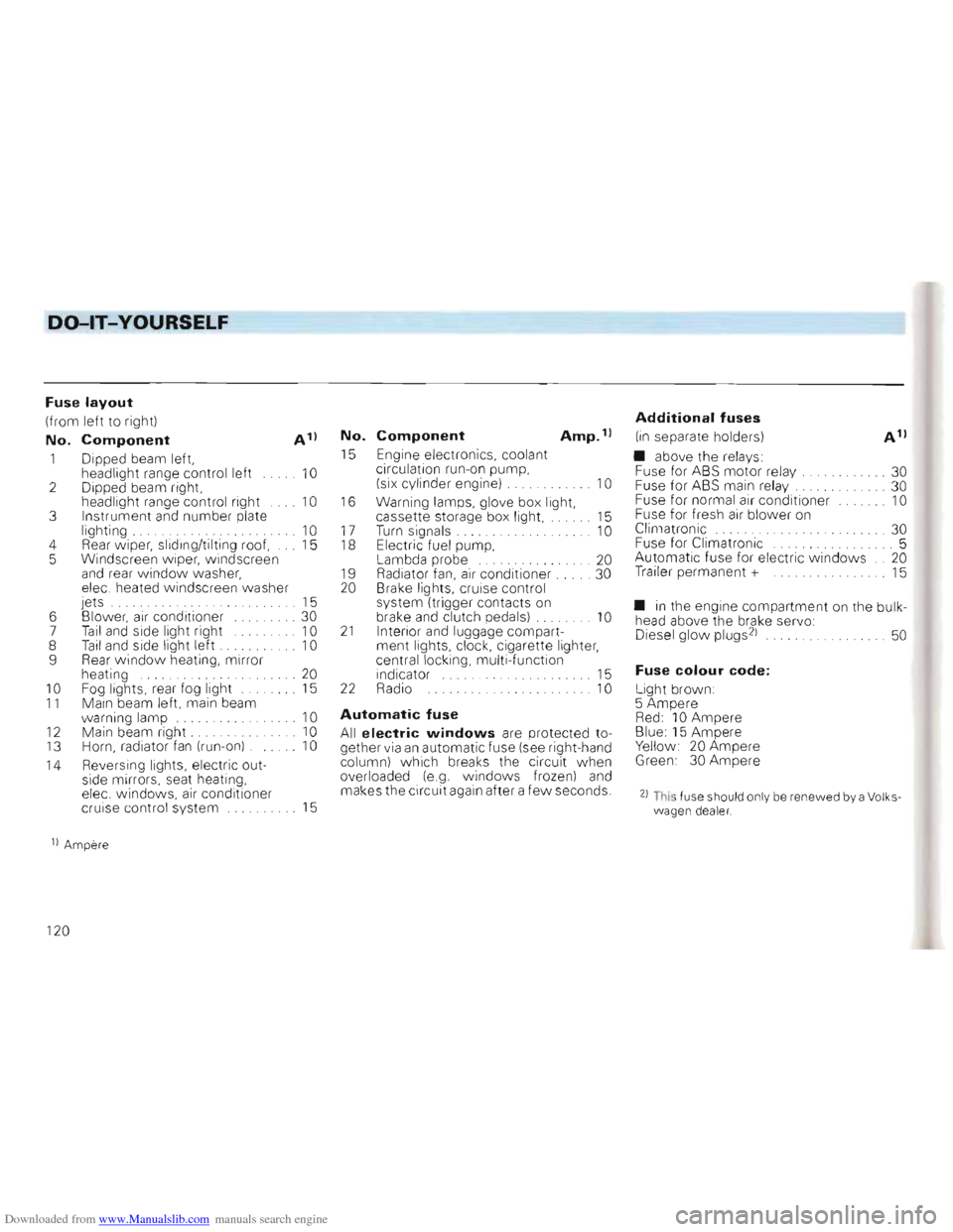
Fuse layout
(from left to rig ht)
No. Component A 1)
1 Dipped beam left,
headlight range control left 10 2 Dipped beam right,
head light ra nge co ntrol right 10 3 Instrument and number plate
light ing . 10 4 Rear w iper, slid ing/tilti ng roo f, 15
5 Windscreen w ipe r, windscr een
a
nd rea r w indo w was her,
ele c. heated windsc reen washer
jets . . . . . . 15
6 Blower,
air co nditi oner ... . 30
7 Tail and side light ri ght 10
8 Tail and side light left . . 10
9 Rear window heating , mirror
heating ... 20 10 F og lights, rear fog light 15 11 Main beam left, main beam
w arnin g lamp 10
12 Mai n bea m right . 10
13 Horn, radiator fan (run- on) . 10
14 Reve
rsi ng lights, electric out
side mirrors, seat heating,
elec. w ind ows,
air conditio ne r
cruis e contro l system 15
No. Component Amp. 1)
15 Engine elec tronics , cool ant
c irculat ion run- on pump,
(six cylinder engine)
.. . .. .. . . . 10
16
Warning lamps, glove box light,
cas sette sto rage box light, 15
17 T urn sig nals. . . . . . . . . . . . .. 10 18 Electri c fue l pum p,
Lambda probe ..... .. ....... 20
1 9 Radiat or fan, air cond itioner. . 30
20 Brake lights, cruise control
syste m (tri gger conta cts
on brake and clutch pedals) . 10 21 Interior and luggage compart
ment lights, clock, cigarette lighter,
ce ntral
locking, multi -function
indicator 15 22 Radio 10
Automatic fuse
All electric windows are protected to
ge ther via an automatic fu se (see rig ht -hand
co lum n) which breaks the circuit when
overloaded (e .g. windows frozen) and makes the circuit again after a few seconds.
Additional fuses
(in separate holders)
• above the
rela ys:
Fu se for ABS motor re lay. ..... . .... 30
Fuse for ABS main relay. ... 30
Fuse for normal air conditioner 10
Fuse for fresh air blower on
Climatronic ... ... ... . 30
Fuse for C1imatronic .. .... ... 5
Automatic fuse for electric w indo ws .. 20
Trailer perma nent + 15
• in the engin e compa rtment on the bulk
head above the brake servo:
Diesel glow plugs 21 . . 50
Fuse colour code:
Light brown :
5 Amper e
Red: 10 Ampere Blue: 15 Ampere Yellow 20 Ampere Green 30 Ampere
21 This fuse shou ld onl y be renewed by a Volks wagen dea ler.
1) Amper e
120
Page 123 of 156
Downloaded from www.Manualslib.com manuals search engine DO-lT-YOURSELF
Changing bulbs
Before starting to replace a bulb, switch off
the light concerned.
Do not touch the glass part of the new bulb
with bare fingers because the finger marks
left
on the glass evaporate when the bulb
becomes hot. the vapour settles on the
reflector and dims it.
Always use the same type of bulb . The des
ignati
on is marked on the base of the bulb
or on the glass .
It
is advisab le to always a carry a box of
spare bulbs in the vehicle . These can be ob
tained from Volkswagen dealers. It shou ld
contain at least the following bulbs w
hich are essentia l for traffic safety:
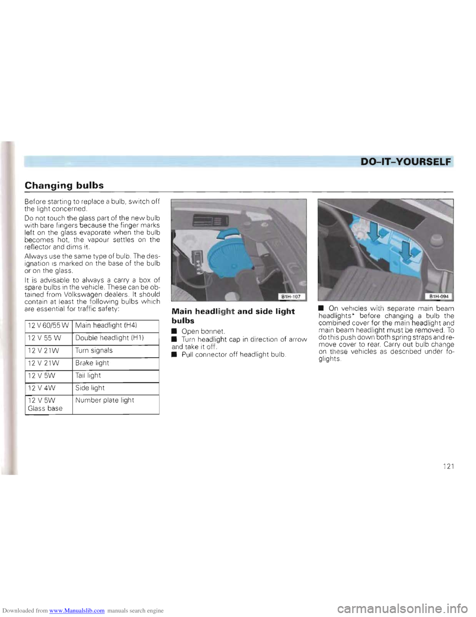
12 V60/55W Main headlight (H4)
12 V 55 W Double h
eadl igh t (H 1)
12 V 21W Turn signa ls
12 V 21W Brake light
12 V 5W Tail light
12
V4W Side light
12 V5W Number plate light
Glass base
Main headlight and side light
bulbs
• Open bon net.
• Turn hea dligh t cap in di rect ion of arrow
a n d ta ke it off.
• Pull connector
off head light bulb. •
On vehicles
w ith separate main beam
h eadligh ts · before changing a bulb the
com bined cover for the main headlight and main beam headlight must be remo ved. To dothis push down both spring straps and re
move cove r to rear. Carry out bulb change
o n these vehicles as descr ib ed und er fo
glights.
1
21
Page 124 of 156
Downloaded from www.Manualslib.com manuals search engine DO-lT-YOURSELF
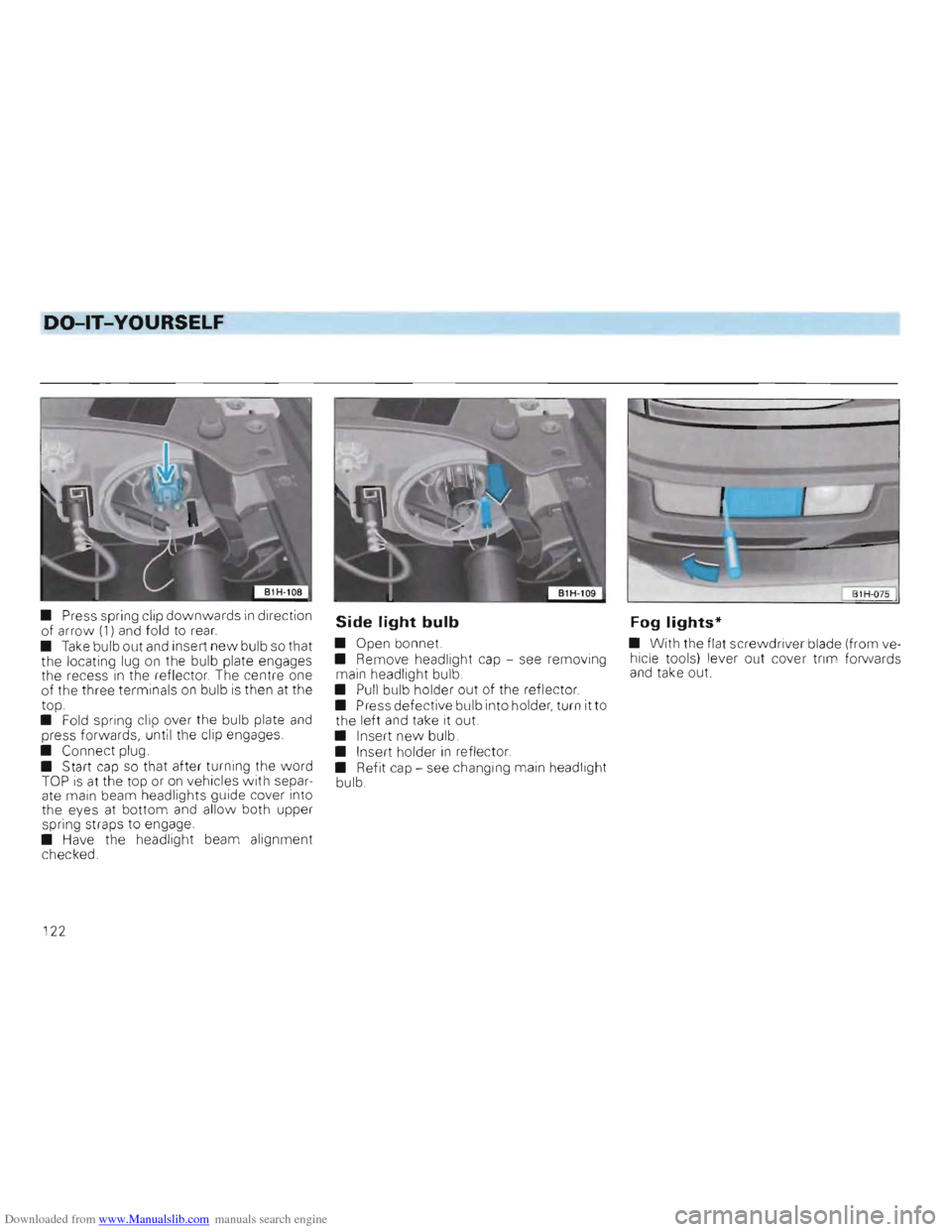
• Press spring clip downwards in direction
of arro\lv (1) and fold to rear.
• Take bulb out and insert new bulb so that
the locating lug on the bulb plate engages
the recess in the reflector. The centre one
of the three terminals on bulb is then at the
top.
• Fold spring clip over the bulb plate
and press forwards, until the clip engages .
• Connect plug.
• Start
cap so that after turning the word TOP is at the top or on vehicles with separ
ate main beam headlights guide cover into
the eyes at bottom
and allo w both upper
spring str aps to engage .
•
Have the headlight beam alignment
chec ked .
Side light bulb Fog lights*
• Open bonnet. •
With the flat screwdriver blade (from ve
• Remove headlight cap -see removing hicle
tools) lever out cover trim forwa rds
main headlight bulb. and take out.
• Pull bulb holder out of the reflector.
• Press defective bulb into holder , turn it to
the left
and take it out.
• Insert
new bulb.
• Insert holder in reflector.
• Refit cap -see chang ing main headlight
bulb.
122
Page 125 of 156
Downloaded from www.Manualslib.com manuals search engine DO-lT-YOURSELF
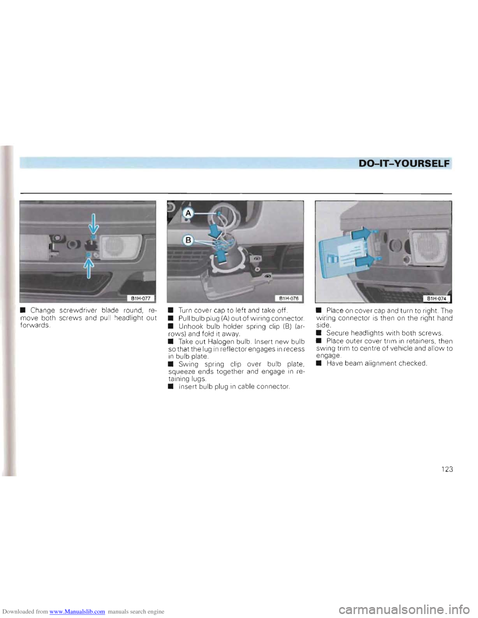
• Change screwdriver blade round, re
move both screws and pull headlight out forw ards. •
Turn cover
cap to left and take off.
• Pull bulb plug (A) out of wiring connector.
• Unhook bulb holder spring clip (8) (arrows) and fold it away.
•
Take out Halogen bulb. Insert new bulb
so that the lug in reflector engages in recess in bulb plate.
• Sw ing spring clip over bulb plate,
squeeze ends together and engage in
re
taining lugs.
• Inse rt bulb plug
in cable connector. •
Plac e
on cover cap and turn to right. The wiring connector is then on the right hand
side.
• Sec ure headlights
with both screws.
• Place outer cover trim in retainers, then
swing trim to centre of vehicle and allow to
engage.
• Have beam alignment checked .
123
Page 126 of 156
Downloaded from www.Manualslib.com manuals search engine DO-lT-YOURSELF
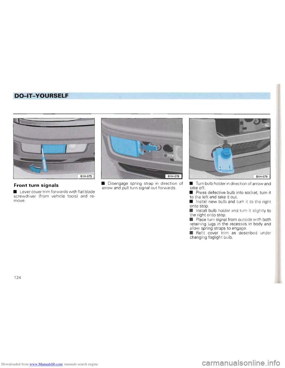
• Disengage spring strap in direct ion of Front turn signals arro w and pull turn signa l out forwards .
• Lever cover trim forwards w ith flat blade
scre
wdri ver (from vehicle tools) and re
move.
• Turn bulb holder in direction of arro w and
tak e off.
•
Press defec tive bulb into socket, turn it
to the left and take it out .
• Insta
ll new bulb and turn it to the right
on to stop.
• Install bulb holder and turn it slight ly to th e r igh t ont o stop.
• Place tu
rn sign al fr om outside with both
retainin g lugs in the rec esse s in body and
allo w spring straps to engage
• Refi t cov er tr im
as d e sCi"lbed under
chang in g fogl ight bUlb.
124
Page 127 of 156
Downloaded from www.Manualslib.com manuals search engine DO-lT-YOURSELF
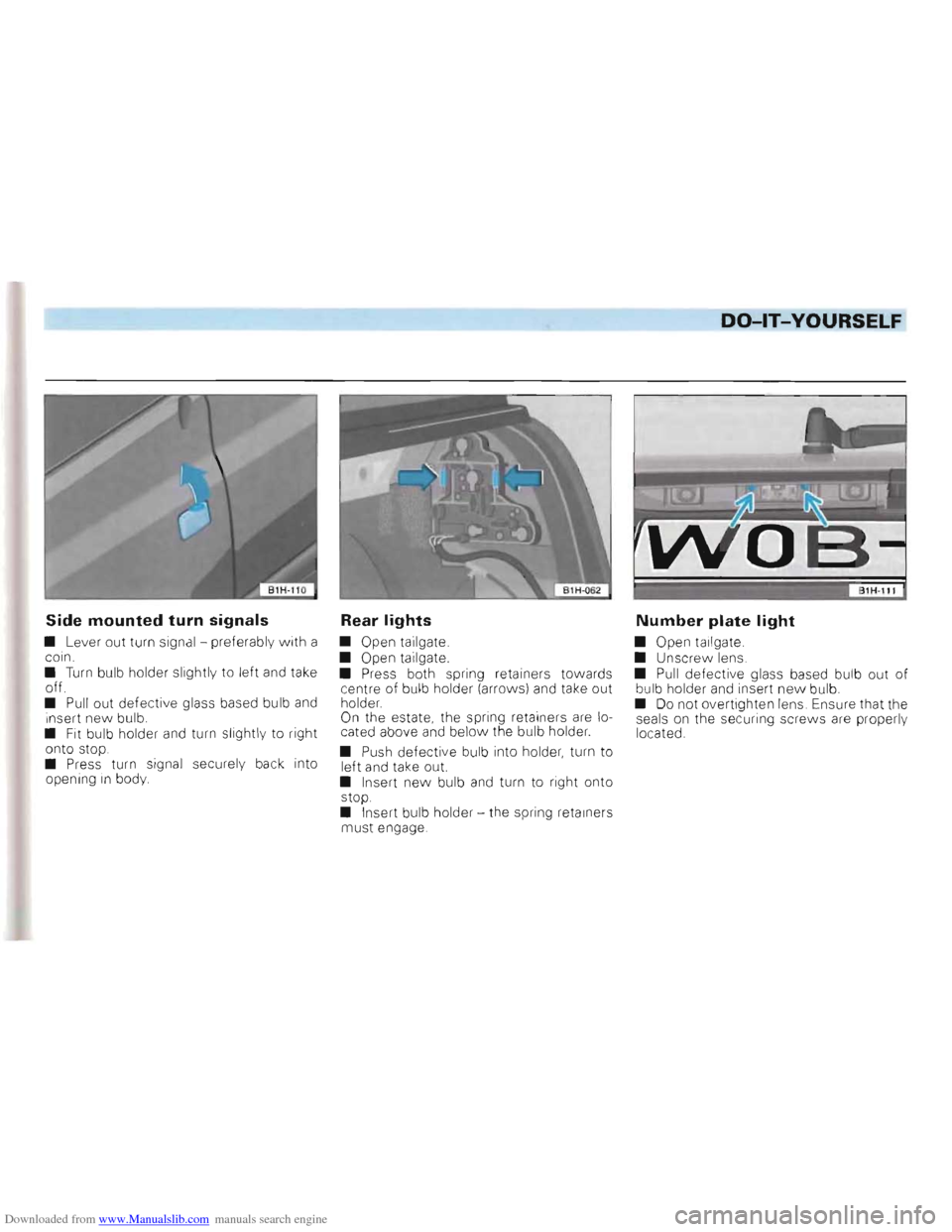
Side mounted turn signals
• Lever out turn signa l - preferab ly with a
coin.
•
Turn bulb holder slightly to left and take off.
• Pull out defective glass based bu lb and i nsert new bulb.
• Fit bulb holder and turn slightly to right
onto stop.
• Press turn signal securel y
back into
openin g in body
Rear lights
• Open tailgate.
• Open tailgate.
• Press both spring retainers towards
centre of bulb holder (arrows)
and take out
holder.
On the estate , the spring retainers are lo
cated above and below the bulb holder.
•
Push defecti ve bulb into holder , turn to
left and take out.
• Insert
new bulb and turn to right onto
stop .
•
Inser t bulb holder -the spring retainers
mus t engage.
Number plate light
• Open tailgate.
• Unscrew lens.
•
Pull defective glass based bulb out of bu lb holder and insert new bu lb.
• Do not overtighten lens . Ensure that the
seals on the secur ing screws are properly
located .
Page 128 of 156
Downloaded from www.Manualslib.com manuals search engine DO-lT-YOURSELF
B1 H-073
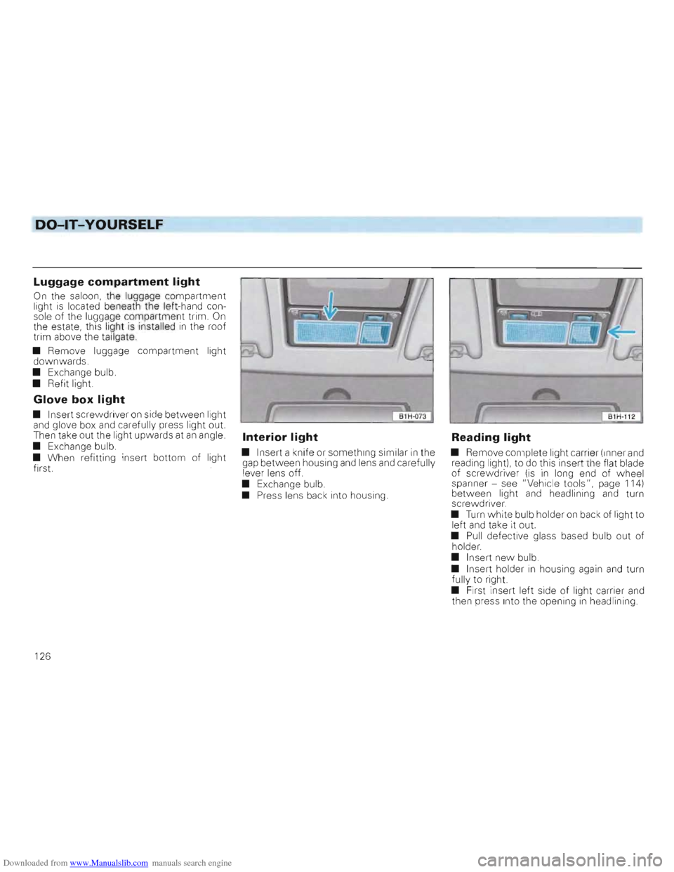
Luggage compartment light
On the saloon, the luggage compartment light is located beneath the left-hand con
sole of the luggage compartment trim. On the estate, this light is installed in the roof
trim above the tai lgate.
• Remove luggage
compartment light
downwards.
• Exchange bulb.
• Refit
light
Glove box light
• Insert screwdriver on side between light
and glove box and carefully press light out.
Then take out
the light upwards at an angle.
• Exchange bulb.
• When refitting insert
bottom of light first
Interior light
• Insert a knife or something similar in the
gap between housing and lens and carefully
lever lens off.
• Exchange bulb.
• Press lens back into housing.
Reading light
• Remove complete light carrier (Inner and
reading light), to do this inser t th e flat blade
of screwdriver
(is in long end of wheel
spanner -see "Vehicle tools", page 114)
between light and headlining and turn
screwdriver.
•
Turn white bulb holder on back of light to left and take it out.
•
Pull defective glass based bulb out of
holder.
• Insert
new bulb.
• Insert holder in housing again and turn
fully to right
• First insert left side of light carrier and
then press Into the opening in headlining
126
Page 129 of 156
Downloaded from www.Manualslib.com manuals search engine DO-lT-YOURSELF
Installing radio
When service installing a radio or replacing
a set installed by the factory the following
points should be noted
• The connection "
in the vehicle is for
Genuine Volkswagen radiosll from Model Year 1994.
• Radios with oth er con nections must be
connected with a n adapter cab le which can also be obtained from a Volkswagen dealer.
Attention On no account cut wires off and leave them without insulation. If necessary use a proper adapter. Otherwise the wiring can be overloaded or short circuits can occur -Fire danger!
11 Not availab le i n all export mark ets
Apart from this, important electronic components can be damaged or the functioning impaired. If for example the speed signal is disturbed this can lead to faulty engine management, automatic gearbox, ABS etc.
Even connecting the speed signal to radio sets with speed dependent volume control from other manufacturers can cause such faults.
• It is advisab le therefore to have the in
sta llation of the radio system done by a Volkswagen dealer. They are fully informed
about the technical features of the vehicle,
have the Genuine radios
1), the necessary
fitting parts from the Genuine Volksvvagen
Accessory Programme 1
) and work in ac
cordance with the guidelines developed by
the factory . •
The radios from the Genuine Volk
swa gen Accessory Programme
1
) are similar
to those used in the factory and ensure
trouble-free Installation .
These sets are
in keeping with the advanced technology and well-planned easy
to-operate design.
In Germany there is also an Exchange Ser
vice for the se radios so that even after years
of use a set requir ing repair
can be ex
changed cheaply for a completely recondi
tioned, good-as-new set by a Volkswagen
dealer.
• Loudspeakers, fitting parts, aerials and
supp
ression kits shou ld also be taken from
the Genuine Volkswagen Accessory Pro
gramme1) These parts have all been
specially developed for each vehicle model.
127
Page 130 of 156
Downloaded from www.Manualslib.com manuals search engine ----DO-lT-YOURSELF
Emergency starting
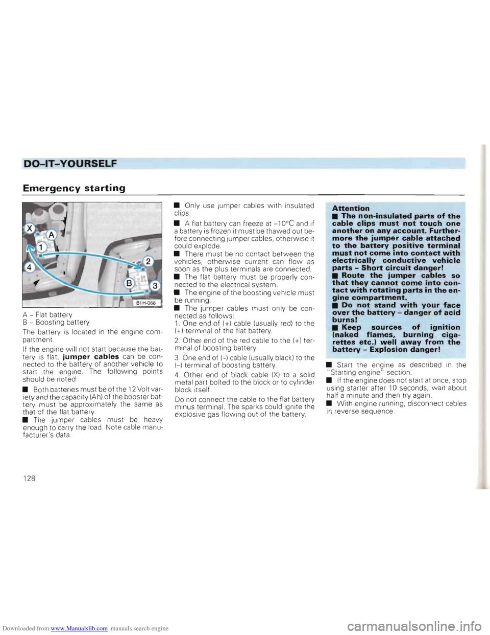
A -Flat battery
B - Boosting battery
The battery
is located in the engine com
partment.
I f the engine will not start because the bat
tery is flat.
jumper cables can be con
nected to the battery of another vehicle to
start the engine . The follow ing points
should be noted
• Both batteries
must be of the 12 Volt var
iety and the capacity (Ah) of the booster bat
tery must be app roximately the same as that of the flat battery .
• The jumper cables must be heavy
enough to carry the load. Note cable manu
facture r's data. •
Only use Jumper cabl
es with insulated
clips.
• A flat battery
can freeze at -1 Ooe and if
a battery is frozen it must be thawed out be
fore connecting Jumper cables, o th erwise it
could explode.
• There
must be no contact between the
vehic les, other wise current can flo w as soon as the plus terminal s are connected .
• The flat battery
must be properly con
nected to the electrical system.
• The engine of the boosting vehicle
must be running.
•
The jumper cables must only be con
nected as follo w s: 1. One end of (+) cable (usually red) to the (+) term inal of the flat battery.
2 . Other end of the red cable to the (+l ter
minal
of boosting battery.
3. One end of H cable (usually black) to the
H terminal of boosting battery.
4. Other end of blac k cable (X) to a solid
metal part bolted to th e block or to cylinder
block itself.
Do not connect the cable to the flat battery
m in us terminal. The sparks could Ignite the
exp losive gas flowing out of the battery
Attention • The non-insulated parts of the cable clips must not touch one another on any account. Furthermore the jumper cable attached to the battery positive terminal must not come into contact with electrically conductive vehicle parts -Short circuit danger! • Route the jumper cables so that they cannot come into contact with rotating parts in the engine compartment. • Do not stand with your face over the battery -danger of acid burns! • Keep sources of igni~ion(naked flames, burning cIgarettes etc.) well away from the battery -Explosion danger!
• Start the engine as described in the
"Starting engine" section.
• If the engine does not start at once, stop
using starter after
10 seconds, wait about
half a minute and then try aga in.
• With engine running, disconnect cables in reverse sequence .
1 28