ESP VOLKSWAGEN JETTA 1998 User Guide
[x] Cancel search | Manufacturer: VOLKSWAGEN, Model Year: 1998, Model line: JETTA, Model: VOLKSWAGEN JETTA 1998Pages: 339, PDF Size: 2.35 MB
Page 147 of 339
Downloaded from www.Manualslib.com manuals search engine 01-144
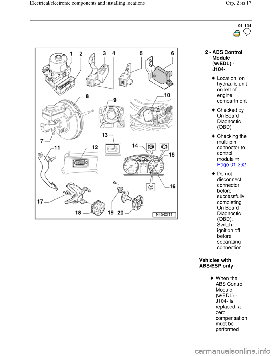
Vehicles with
ABS/ESP only 2 -
ABS Control
Module
(w/EDL) -
J104-
Location: on
hydraulic unit
on left of
engine
compartment
Checked by
On Board
Diagnostic
(OBD)
Checking the
multi-pin
connector to
control
module
Page 01
-292
Do not
disconnect
connector
before
successfully
completing
On Board
Diagnostic
(OBD).
Switch
ignition off
before
separating
connection.
When the
ABS Control
Module
(w/EDL) -
J104- is
replaced, a
zero
compensation
must be
performed
Стр. 2из 17 Electrical/electronic components and installing locations
Page 149 of 339
Downloaded from www.Manualslib.com manuals search engine 01-145
Repair Manual,
Brake System, Repair
Group 45; Removing
and installing parts of
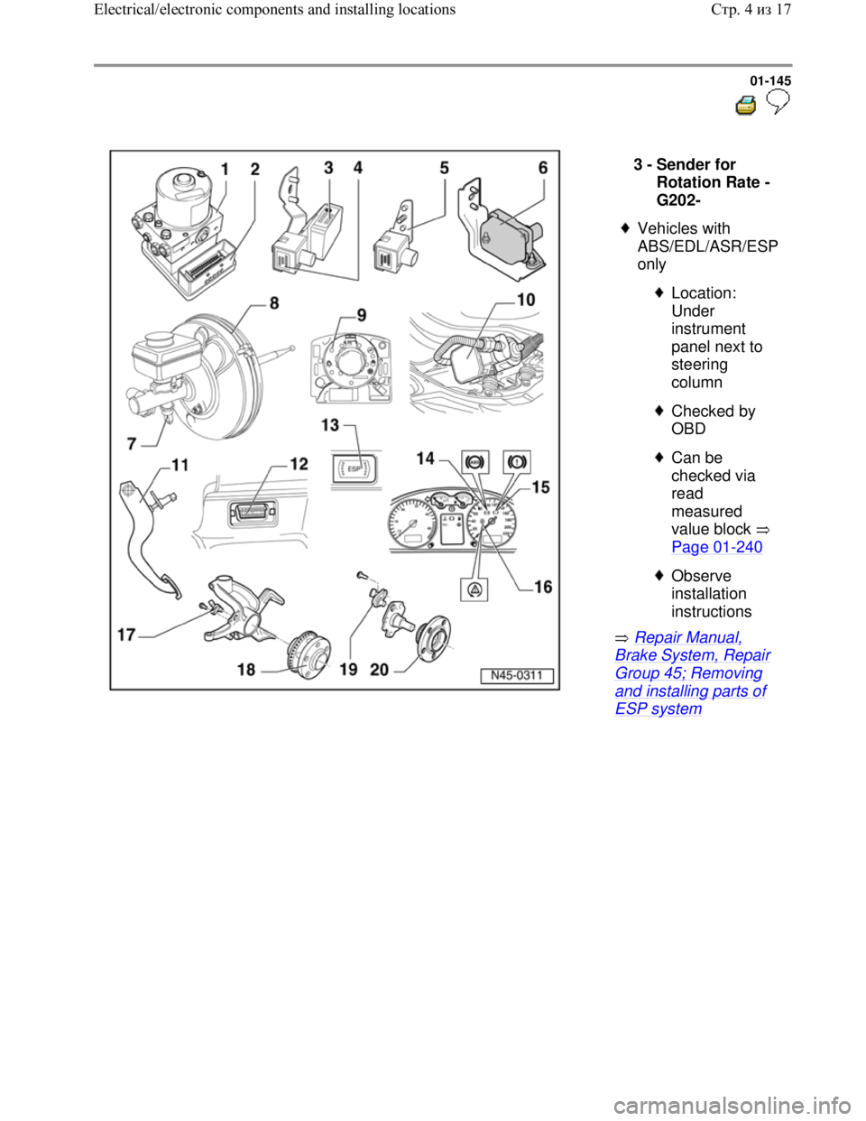
ESP system 3 -
Sender for
Rotation Rate -
G202-
Vehicles with
ABS/EDL/ASR/ESP
only
Location:
Under
instrument
panel next to
steering
column
Checked by
OBD
Can be
checked via
read
measured
value block
Page 01
-240
Observe
installation
instructions
Стр. 4из 17 Electrical/electronic components and installing locations
Page 150 of 339
Downloaded from www.Manualslib.com manuals search engine 01-146
Repair Manual,
Brake System, Repair
Group 45; Removing
and installing parts of
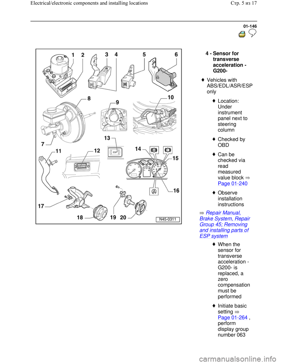
ESP system 4 -
Sensor for
transverse
acceleration -
G200-
Vehicles with
ABS/EDL/ASR/ESP
only
Location:
Under
instrument
panel next to
steering
column
Checked by
OBD
Can be
checked via
read
measured
value block
Page 01
-240
Observe
installation
instructions
When the
sensor for
transverse
acceleration -
G200- is
replaced, a
zero
compensation
must be
performed
Initiate basic
setting
Page 01
-264 ,
perform
display group
number 063
Стр. 5из 17 Electrical/electronic components and installing locations
Page 152 of 339
Downloaded from www.Manualslib.com manuals search engine 01-148
Repair Manual,
Brake System, Repair
Group 45; Removing
and installing parts of
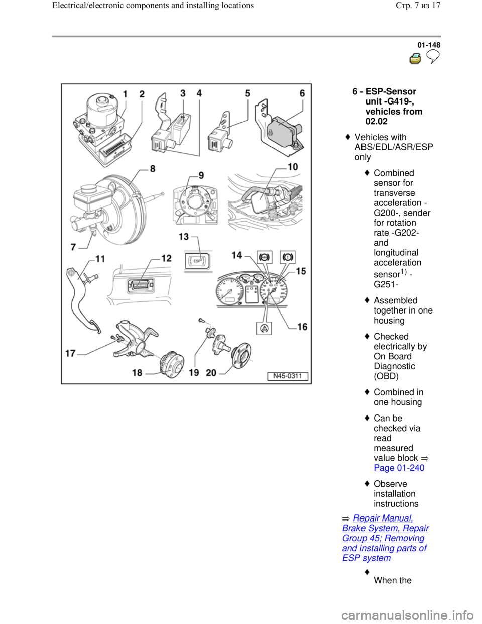
ESP system 6 -
ESP-Sensor
unit -G419-,
vehicles from
02.02
Vehicles with
ABS/EDL/ASR/ESP
only
Combined
sensor for
transverse
acceleration -
G200-, sender
for rotation
rate -G202-
and
longitudinal
acceleration
sensor
1) -
G251-
Assembled
together in one
housing
Checked
electrically by
On Board
Diagnostic
(OBD)
Combined in
one housing
Can be
checked via
read
measured
value block
Page 01
-240
Observe
installation
instructions
When the
Стр. 7из 17 Electrical/electronic components and installing locations
Page 153 of 339

Downloaded from www.Manualslib.com manuals search engine ESP-sensor
unit -G419- is
replaced, a
zero
compensation
must be
performed
Initiate basic
setting
Page 01
-264 ,
perform
display group
numbers 063
and 069
1) 4Motion
vehicles with
Haldex clutch
only
Стр. 8из 17 Electrical/electronic components and installing locations
Page 154 of 339
Downloaded from www.Manualslib.com manuals search engine 01-149
Repair Manual,
Brake System, Repair
Group 47; Assembly
overview: Brake
booster/brake master
cylinder for vehicles
with
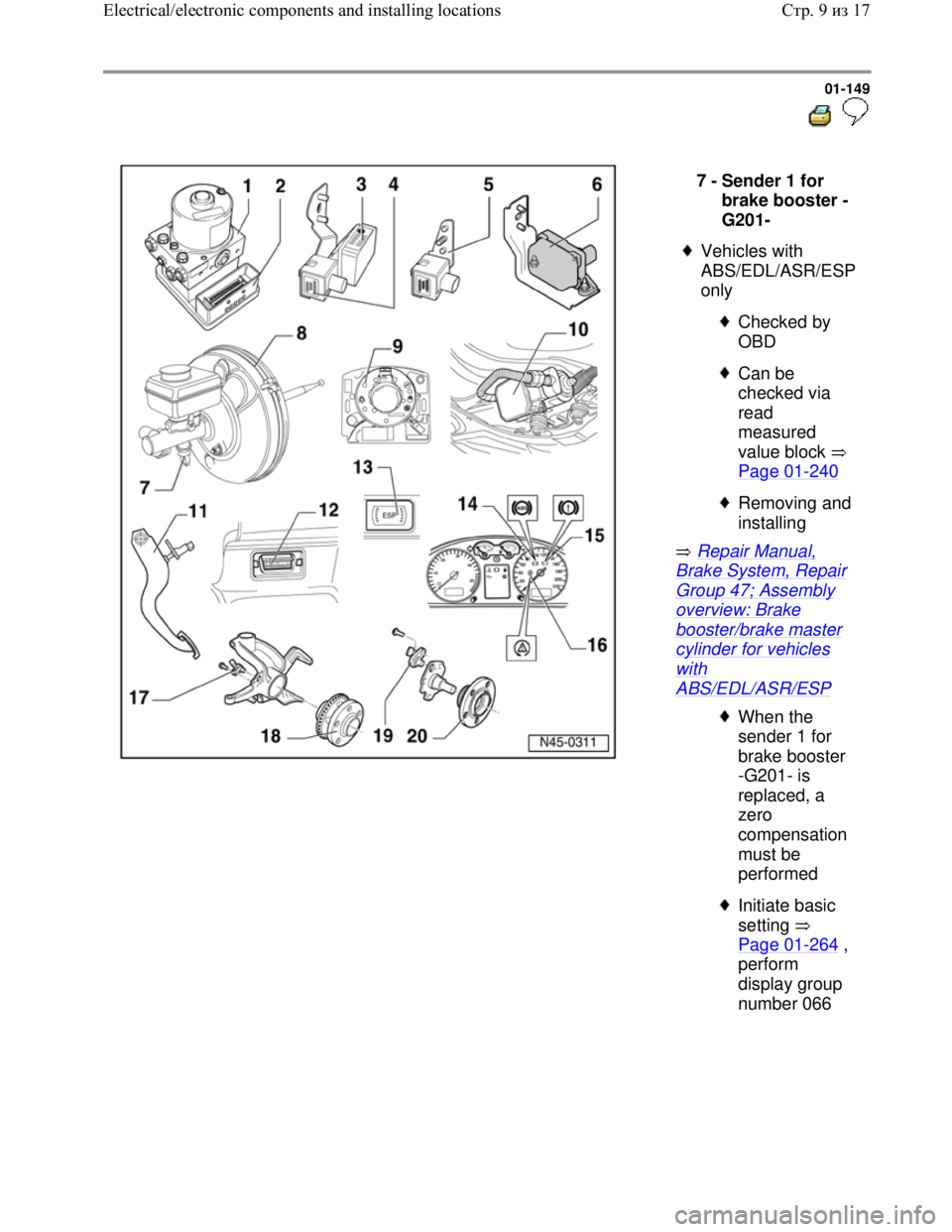
ABS/EDL/ASR/ESP 7 -
Sender 1 for
brake booster -
G201-
Vehicles with
ABS/EDL/ASR/ESP
only
Checked by
OBD
Can be
checked via
read
measured
value block
Page 01
-240
Removing and
installing
When the
sender 1 for
brake booster
-G201- is
replaced, a
zero
compensation
must be
performed
Initiate basic
setting
Page 01
-264 ,
perform
display group
number 066
Стр. 9из 17 Electrical/electronic components and installing locations
Page 155 of 339
Downloaded from www.Manualslib.com manuals search engine 01-150
Repair Manual,
Brake System, Repair
Group 45; Removing
and installing parts of
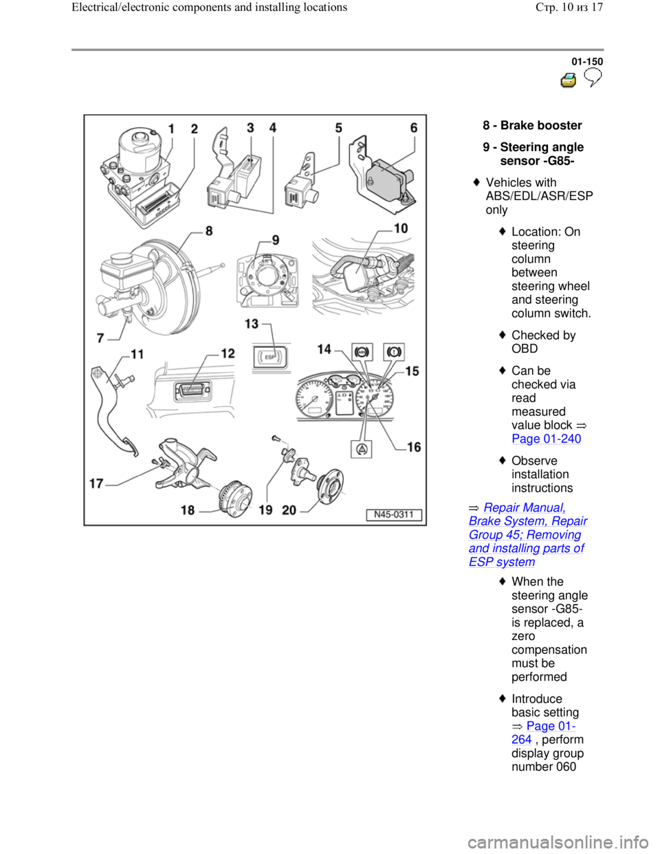
ESP system 8 -
Brake booster
9 -
Steering angle
sensor -G85-
Vehicles with
ABS/EDL/ASR/ESP
only
Location: On
steering
column
between
steering wheel
and steering
column switch.
Checked by
OBD
Can be
checked via
read
measured
value block
Page 01
-240
Observe
installation
instructions
When the
steering angle
sensor -G85-
is replaced, a
zero
compensation
must be
performed
Introduce
basic setting
Page 01
-
264 , perform
display group
number 060
Стр. 10из 17 Electrical/electronic components and installing locations
Page 158 of 339
Downloaded from www.Manualslib.com manuals search engine 01-152
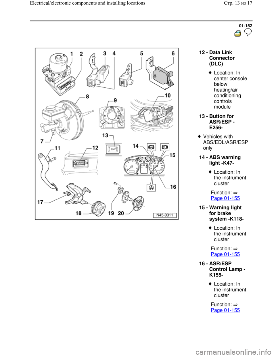
12 -
Data Link
Connector
(DLC)
Location: In
center console
below
heating/air
conditioning
controls
module
13 -
Button for
ASR/ESP -
E256-
Vehicles with
ABS/EDL/ASR/ESP
only
14 -
ABS warning
light -K47-
Location: In
the instrument
cluster
Function:
Page 01
-155
15 -
Warning light
for brake
system -K118-
Location: In
the instrument
cluster
Function:
Page 01
-155
16 -
ASR/ESP
Control Lamp -
K155-
Location: In
the instrument
cluster
Function:
Page 01
-155
Стр. 13из 17 Electrical/electronic components and installing locations
Page 163 of 339
Downloaded from www.Manualslib.com manuals search engine 01-155
Diagnostic Trouble Codes
(DTCs) displayed by
warning lights -K47-, -K118-
and -K155-
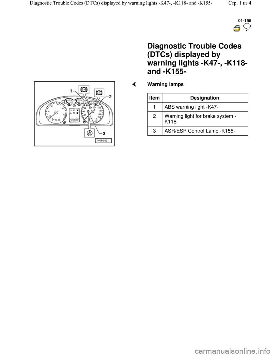
Warning lamps
Item
Designation
1 ABS warning light -K47-
2 Warning light for brake system -
K118-
3 ASR/ESP Control Lamp -K155-
Стр. 1из 4 Diagnostic Trouble Codes (DTCs) displayed by warning lights -K47-, -K118- and -K155-
Page 166 of 339
Downloaded from www.Manualslib.com manuals search engine 01-158
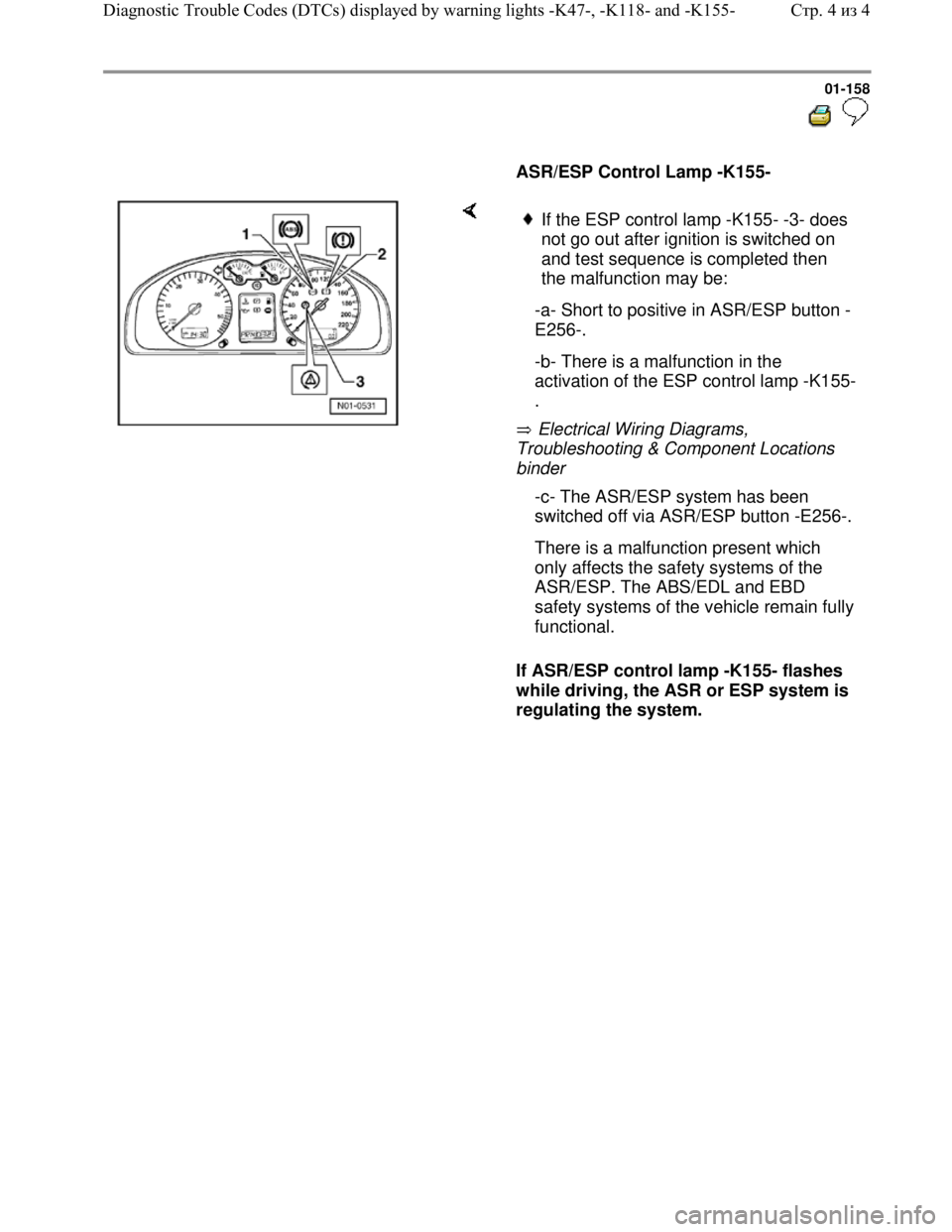
ASR/ESP Control Lamp -K155-
Electrical Wiring Diagrams,
Troubleshooting & Component Locations
binder
If ASR/ESP control lamp -K155- flashes
while driving, the ASR or ESP system is
regulating the system.
If the ESP control lamp -K155- -3- does
not go out after ignition is switched on
and test sequence is completed then
the malfunction may be:
-a- Short to positive in ASR/ESP button -
E256-.
-b- There is a malfunction in the
activation of the ESP control lamp -K155-
.
-c- The ASR/ESP system has been
switched off via ASR/ESP button -E256-.
There is a malfunction present which
only affects the safety systems of the
ASR/ESP. The ABS/EDL and EBD
safety systems of the vehicle remain fully
functional.
Стр. 4из 4 Diagnostic Trouble Codes (DTCs) displayed by warning lights -K47-, -K118- and -K155-