brake sensor VOLKSWAGEN JETTA 1998 User Guide
[x] Cancel search | Manufacturer: VOLKSWAGEN, Model Year: 1998, Model line: JETTA, Model: VOLKSWAGEN JETTA 1998Pages: 339, PDF Size: 2.35 MB
Page 47 of 339
Downloaded from www.Manualslib.com manuals search engine 01-44
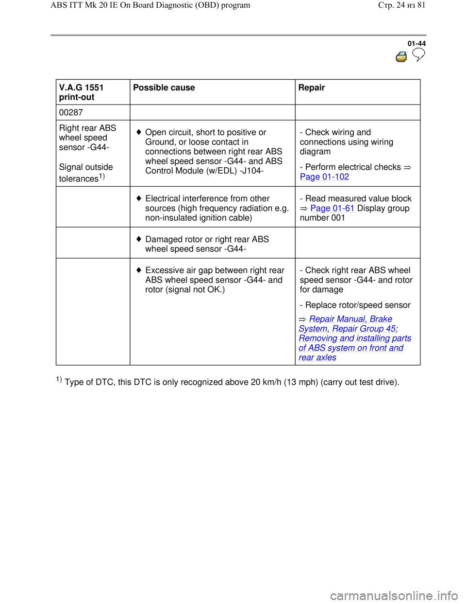
V.A.G 1551
print-out Possible cause
Repair
00287
Right rear ABS
wheel speed
sensor -G44-
Signal outside
tolerances
1)
Open circuit, short to positive or
Ground, or loose contact in
connections between right rear ABS
wheel speed sensor -G44- and ABS
Control Module (w/EDL) -J104- - Check wiring and
connections using wiring
diagram
- Perform electrical checks
Page 01
-102
Electrical interference from other
sources (high frequency radiation e.g.
non-insulated ignition cable) - Read measured value block
Page 01
-61 Display group
number 001
Damaged rotor or right rear ABS
wheel speed sensor -G44-
Excessive air gap between right rear
ABS wheel speed sensor -G44- and
rotor (signal not OK.)
Repair Manual, Brake
System, Repair Group 45;
Removing and installing parts
of ABS system on front and
rear axles - Check right rear ABS wheel
speed sensor -G44- and rotor
for damage
- Replace rotor/speed sensor
1) Type of DTC, this DTC is only recognized above 20 km/h (13 mph) (carry out test drive).
Стр. 24из 81 ABS ITT Mk 20 IE On Board Diagnostic (OBD) program
Page 48 of 339

Downloaded from www.Manualslib.com manuals search engine 01-45
V.A.G 1551 print-
out Possible cause
Repair
00287
Right rear ABS
wheel speed
sensor -G44-
Mechanical
malfunction
1)
Excessive air gap
between right rear ABS
wheel speed sensor -
G44- and rotor (signal
not OK.) Repair Manual, Brake System, Repair
Group 45; Removing and installing parts of
ABS system on front and rear axles - Check installation of right rear ABS
wheel speed sensor -G44- and rotor
- Read measured value block Page 01-
61 Display group number 002
- Perform output Diagnostic Test Mode
(DTM) Page 01
-74
If the malfunction occurs again:
Outlet valve in ABS
hydraulic unit -N55-
faulty Repair Manual, Brake System, Repair
Group 45; Hydraulic unit, brake
booster/brake master cylinder - Assembly
overview; Removing and installing control
module and hydraulic unit - Replace ABS hydraulic unit -N55-
1) Type of DTC, this DTC is only recognized above 20 km/h (13 mph) (carry out test drive).
Стр. 25из 81 ABS ITT Mk 20 IE On Board Diagnostic (OBD) program
Page 49 of 339
Downloaded from www.Manualslib.com manuals search engine 01-46
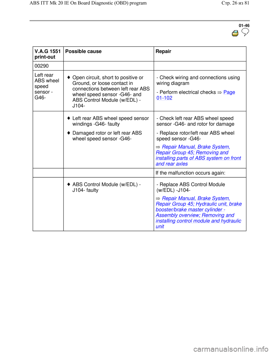
V.A.G 1551
print-out Possible cause
Repair
00290
Left rear
ABS wheel
speed
sensor -
G46-
Open circuit, short to positive or
Ground, or loose contact in
connections between left rear ABS
wheel speed sensor -G46- and
ABS Control Module (w/EDL) -
J104- - Check wiring and connections using
wiring diagram
- Perform electrical checks Page
01-102
Left rear ABS wheel speed sensor
windings -G46- faulty
Damaged rotor or left rear ABS
wheel speed sensor -G46-
Repair Manual, Brake System,
Repair Group 45; Removing and
installing parts of ABS system on front
and rear axles - Check left rear ABS wheel speed
sensor -G46- and rotor for damage
- Replace rotor/left rear ABS wheel
speed sensor -G46-
If the malfunction occurs again:
ABS Control Module (w/EDL) -
J104- faulty
Repair Manual, Brake System,
Repair Group 45; Hydraulic unit, brake
booster/brake master cylinder -
Assembly overview; Removing and
installing control module and hydraulic
unit - Replace ABS Control Module
(w/EDL) -J104-
Стр. 26из 81 ABS ITT Mk 20 IE On Board Diagnostic (OBD) program
Page 50 of 339
Downloaded from www.Manualslib.com manuals search engine 01-47
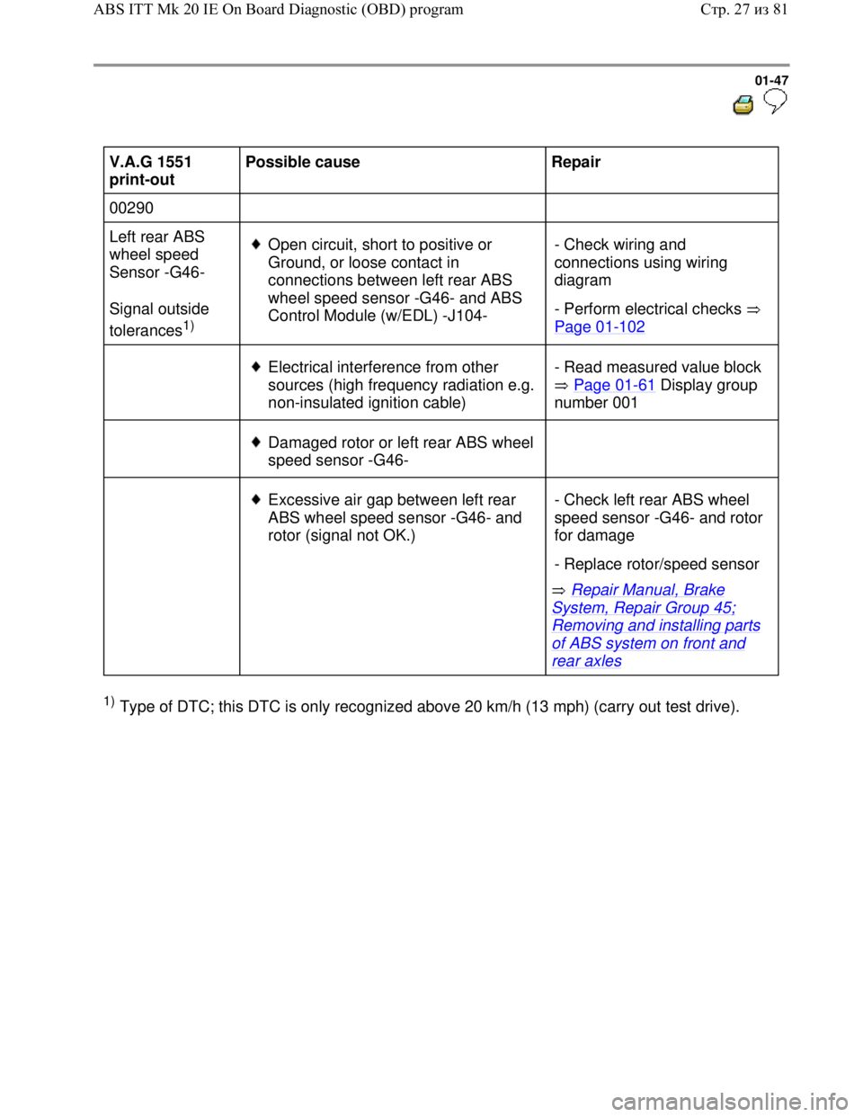
V.A.G 1551
print-out Possible cause
Repair
00290
Left rear ABS
wheel speed
Sensor -G46-
Signal outside
tolerances
1)
Open circuit, short to positive or
Ground, or loose contact in
connections between left rear ABS
wheel speed sensor -G46- and ABS
Control Module (w/EDL) -J104- - Check wiring and
connections using wiring
diagram
- Perform electrical checks
Page 01
-102
Electrical interference from other
sources (high frequency radiation e.g.
non-insulated ignition cable) - Read measured value block
Page 01
-61 Display group
number 001
Damaged rotor or left rear ABS wheel
speed sensor -G46-
Excessive air gap between left rear
ABS wheel speed sensor -G46- and
rotor (signal not OK.)
Repair Manual, Brake
System, Repair Group 45;
Removing and installing parts
of ABS system on front and
rear axles - Check left rear ABS wheel
speed sensor -G46- and rotor
for damage
- Replace rotor/speed sensor
1) Type of DTC; this DTC is only recognized above 20 km/h (13 mph) (carry out test drive).
Стр. 27из 81 ABS ITT Mk 20 IE On Board Diagnostic (OBD) program
Page 51 of 339

Downloaded from www.Manualslib.com manuals search engine 01-48
V.A.G 1551 print-
out Possible cause
Repair
00290
Left rear ABS
wheel speed
sensor -G46-
Mechanical
malfunction
1)
Excessive air gap
between left rear ABS
wheel speed sensor -
G46- and rotor (signal
not OK.) Repair Manual, Brake System, Repair
Group 45; Removing and installing parts of
ABS system on front and rear axles - Check installation of left rear ABS wheel
speed sensor -G46- and rotor
- Read measured value block Page 01-
61 Display group number 002
- Perform output Diagnostic Test Mode
(DTM) Page 01
-74
If the malfunction occurs again:
Outlet valve in ABS
hydraulic unit -N55-
faulty Repair Manual, Brake System, Repair
Group 45; Hydraulic unit, brake
booster/brake master cylinder - Assembly
overview; Removing and installing control
module and hydraulic unit - Replace ABS hydraulic unit -N55-
1) Type of DTC; this DTC is only recognized above 20 km/h (13 mph) (carry out test drive).
Стр. 28из 81 ABS ITT Mk 20 IE On Board Diagnostic (OBD) program
Page 67 of 339
Downloaded from www.Manualslib.com manuals search engine 01-64
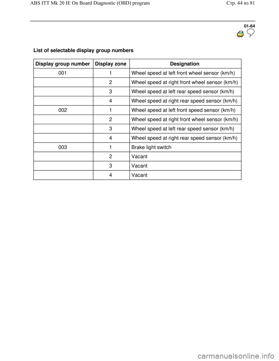
List of selectable display group numbers
Display group number
Display zone
Designation
001 1 Wheel speed at left front wheel sensor (km/h)
2 Wheel speed at right front wheel sensor (km/h)
3 Wheel speed at left rear speed sensor (km/h)
4 Wheel speed at right rear speed sensor (km/h)
002 1 Wheel speed at left front speed sensor (km/h)
2 Wheel speed at right front wheel sensor (km/h)
3 Wheel speed at left rear speed sensor (km/h)
4 Wheel speed at right rear speed sensor (km/h)
003 1 Brake light switch
2 Vacant
3 Vacant
4 Vacant
Стр. 44из 81 ABS ITT Mk 20 IE On Board Diagnostic (OBD) program
Page 111 of 339
Downloaded from www.Manualslib.com manuals search engine 01-108
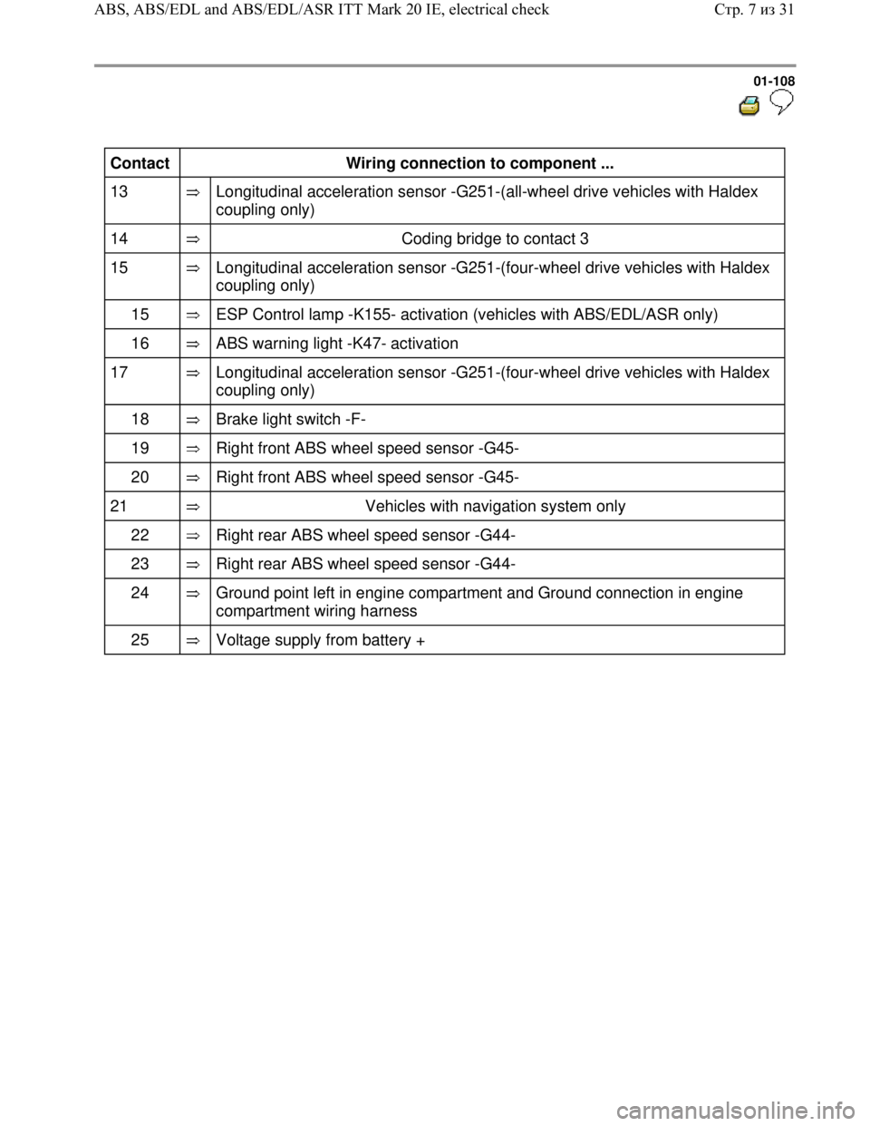
Contact
Wiring connection to component ...
13
Longitudinal acceleration sensor -G251-(all-wheel drive vehicles with Haldex
coupling only)
14
Coding bridge to contact 3
15
Longitudinal acceleration sensor -G251-(four-wheel drive vehicles with Haldex
coupling only)
15
ESP Control lamp -K155- activation (vehicles with ABS/EDL/ASR only)
16
ABS warning light -K47- activation
17
Longitudinal acceleration sensor -G251-(four-wheel drive vehicles with Haldex
coupling only)
18
Brake light switch -F-
19
Right front ABS wheel speed sensor -G45-
20
Right front ABS wheel speed sensor -G45-
21
Vehicles with navigation system only
22
Right rear ABS wheel speed sensor -G44-
23
Right rear ABS wheel speed sensor -G44-
24
Ground point left in engine compartment and Ground connection in engine
compartment wiring harness
25
Voltage supply from battery +
Стр. 7из 31 ABS, ABS/EDL and ABS/EDL/ASR ITT Mark 20 IE, electrical check
Page 112 of 339
Downloaded from www.Manualslib.com manuals search engine 01-109
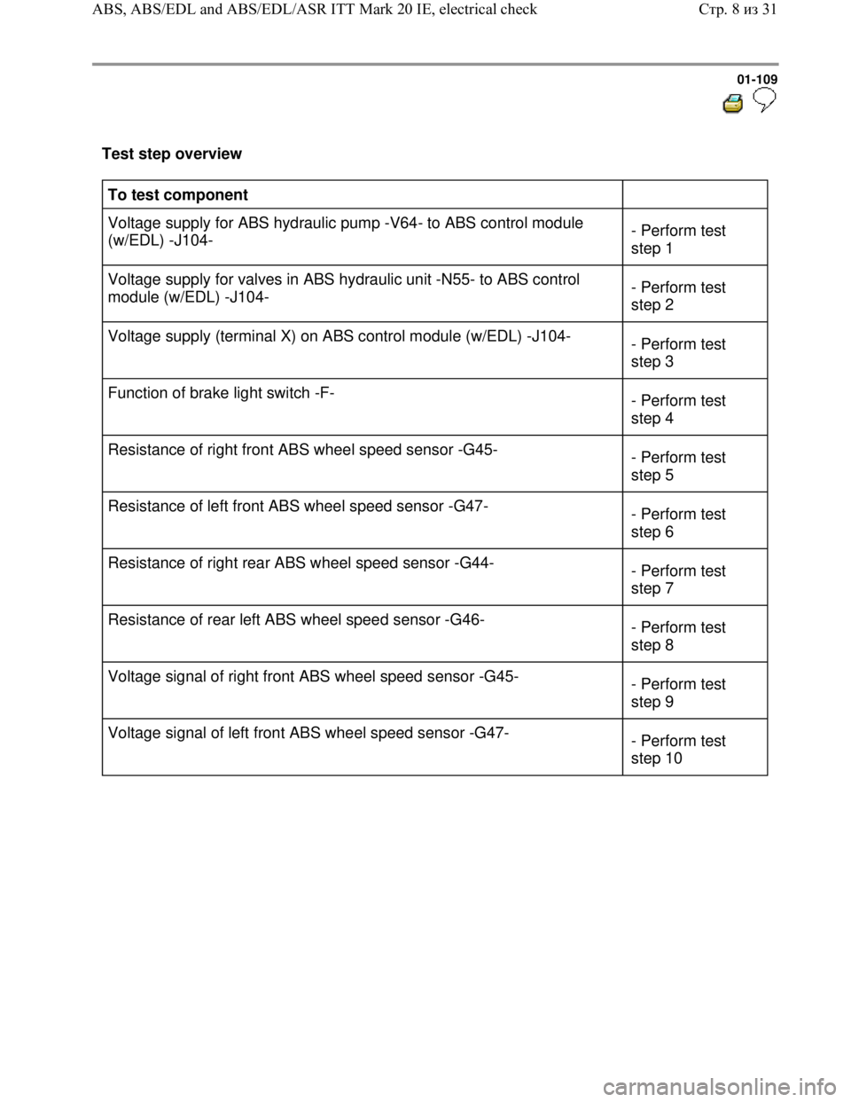
Test step overview
To test component
Voltage supply for ABS hydraulic pump -V64- to ABS control module
(w/EDL) -J104- - Perform test
step 1
Voltage supply for valves in ABS hydraulic unit -N55- to ABS control
module (w/EDL) -J104- - Perform test
step 2
Voltage supply (terminal X) on ABS control module (w/EDL) -J104-
- Perform test
step 3
Function of brake light switch -F-
- Perform test
step 4
Resistance of right front ABS wheel speed sensor -G45-
- Perform test
step 5
Resistance of left front ABS wheel speed sensor -G47-
- Perform test
step 6
Resistance of right rear ABS wheel speed sensor -G44-
- Perform test
step 7
Resistance of rear left ABS wheel speed sensor -G46-
- Perform test
step 8
Voltage signal of right front ABS wheel speed sensor -G45-
- Perform test
step 9
Voltage signal of left front ABS wheel speed sensor -G47-
- Perform test
step 10
Стр. 8из 31 ABS, ABS/EDL and ABS/EDL/ASR ITT Mark 20 IE, electrical check
Page 113 of 339
Downloaded from www.Manualslib.com manuals search engine 01-110
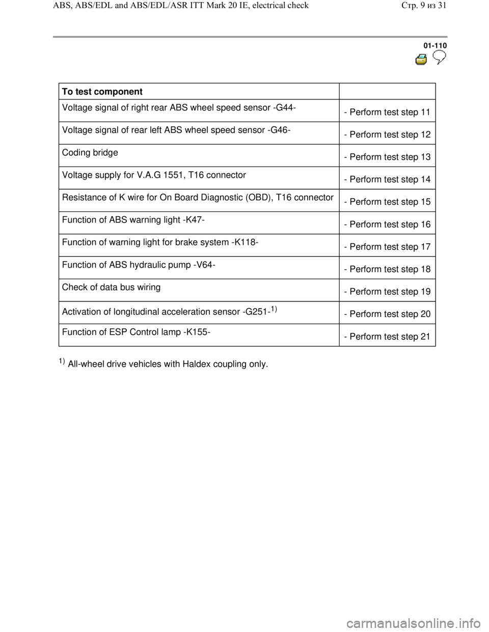
To test component
Voltage signal of right rear ABS wheel speed sensor -G44-
- Perform test step 11
Voltage signal of rear left ABS wheel speed sensor -G46-
- Perform test step 12
Coding bridge
- Perform test step 13
Voltage supply for V.A.G 1551, T16 connector
- Perform test step 14
Resistance of K wire for On Board Diagnostic (OBD), T16 connector
- Perform test step 15
Function of ABS warning light -K47-
- Perform test step 16
Function of warning light for brake system -K118-
- Perform test step 17
Function of ABS hydraulic pump -V64-
- Perform test step 18
Check of data bus wiring
- Perform test step 19
Activation of longitudinal acceleration sensor -G251-
1)
- Perform test step 20
Function of ESP Control lamp -K155-
- Perform test step 21
1) All-wheel drive vehicles with Haldex coupling only.
Стр. 9из 31 ABS, ABS/EDL and ABS/EDL/ASR ITT Mark 20 IE, electrical check
Page 117 of 339
Downloaded from www.Manualslib.com manuals search engine 01-114
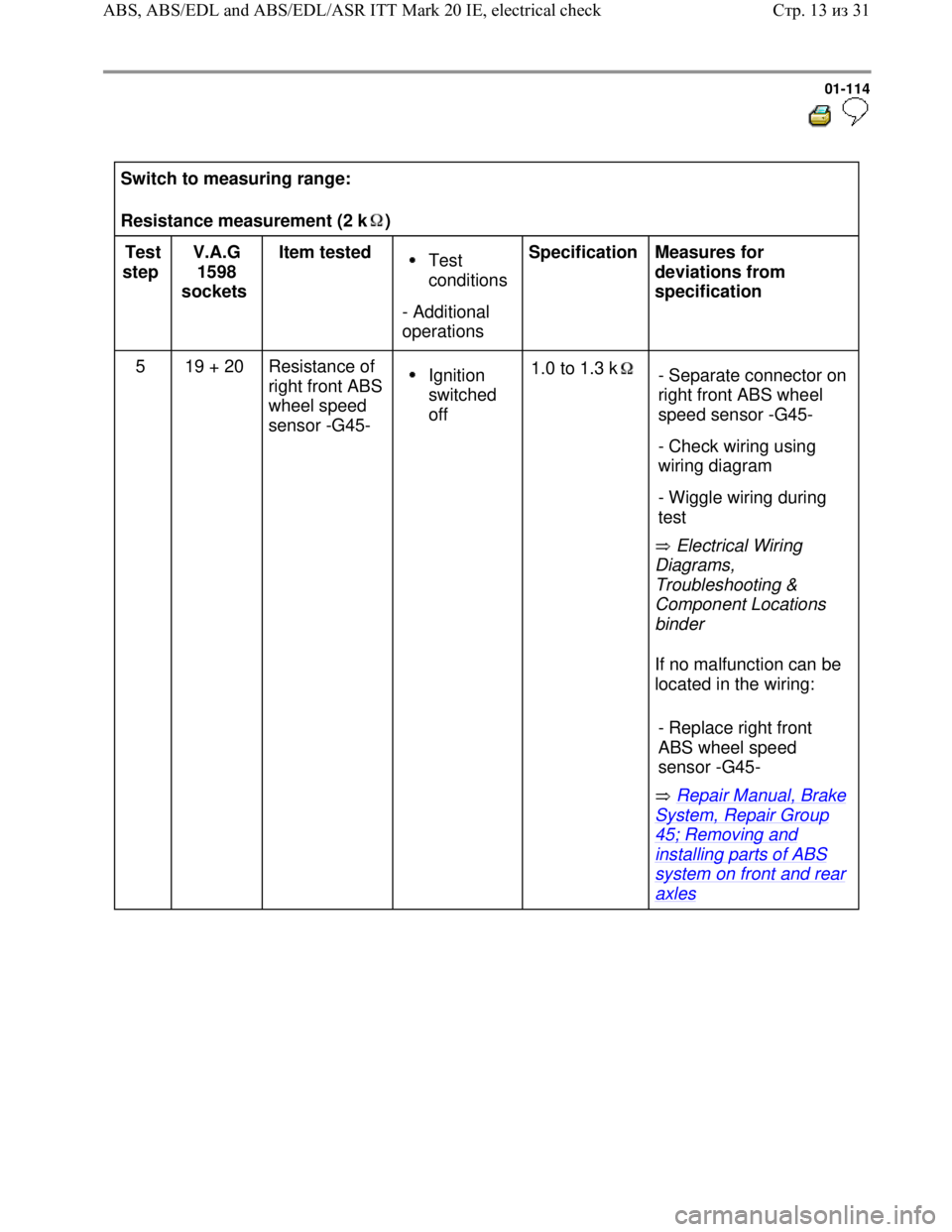
Switch to measuring range:
Resistance measurement (2 k )
Test
step V.A.G
1598
sockets Item tested Test
conditions
- Additional
operations Specification
Measures for
deviations from
specification
5 19 + 20 Resistance of
right front ABS
wheel speed
sensor -G45-
Ignition
switched
off 1.0 to 1.3 k
Electrical Wiring
Diagrams,
Troubleshooting &
Component Locations
binder
If no malfunction can be
located in the wiring:
Repair Manual, Brake
System, Repair Group
45; Removing and
installing parts of ABS
system on front and rear
axles - Separate connector on
right front ABS wheel
speed sensor -G45-
- Check wiring using
wiring diagram
- Wiggle wiring during
test
- Replace right front
ABS wheel speed
sensor -G45-
Стр. 13из 31 ABS, ABS/EDL and ABS/EDL/ASR ITT Mark 20 IE, electrical check