VOLKSWAGEN PASSAT 1995 B3, B4 / 3.G Service Workshop Manual
PASSAT 1995 B3, B4 / 3.G
VOLKSWAGEN
VOLKSWAGEN
https://www.carmanualsonline.info/img/18/7419/w960_7419-0.png
VOLKSWAGEN PASSAT 1995 B3, B4 / 3.G Service Workshop Manual
Trending: check engine, steering wheel adjustment, Sensor, plug, clock reset, clock setting, teves
Page 131 of 369
Downloaded from www.Manualslib.com manuals search engine 42-35
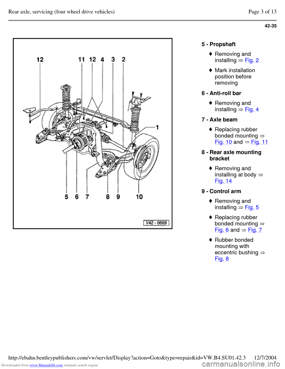
5 - Propshaft Removing and
installing Fig. 2 Mark installation
position before
removing
6 - Anti-roll bar Removing and
installing Fig. 4 7 - Axle beam Replacing rubber
bonded mounting
Fig. 10 and Fig. 11 8 - Rear axle mounting
bracket Removing and
installing at body
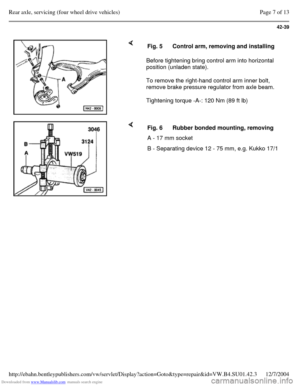
Fig. 14 9 - Control arm Removing and
installing Fig. 5 Replacing rubber
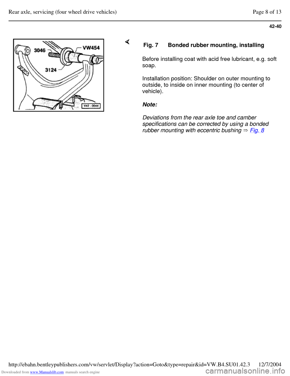
bonded mounting
Fig. 6 and Fig. 7 Rubber bonded
mounting with
eccentric bushing
Fig. 8 Page 3 of 13Rear axle, servicing (four wheel drive vehicles)12/7/2004http://ebahn.bentleypublishers.com/vw/servlet/Display?action=Goto&type=repair&id=VW.B4.SU01.42.3
Page 132 of 369
Downloaded from www.Manualslib.com manuals search engine 42-36
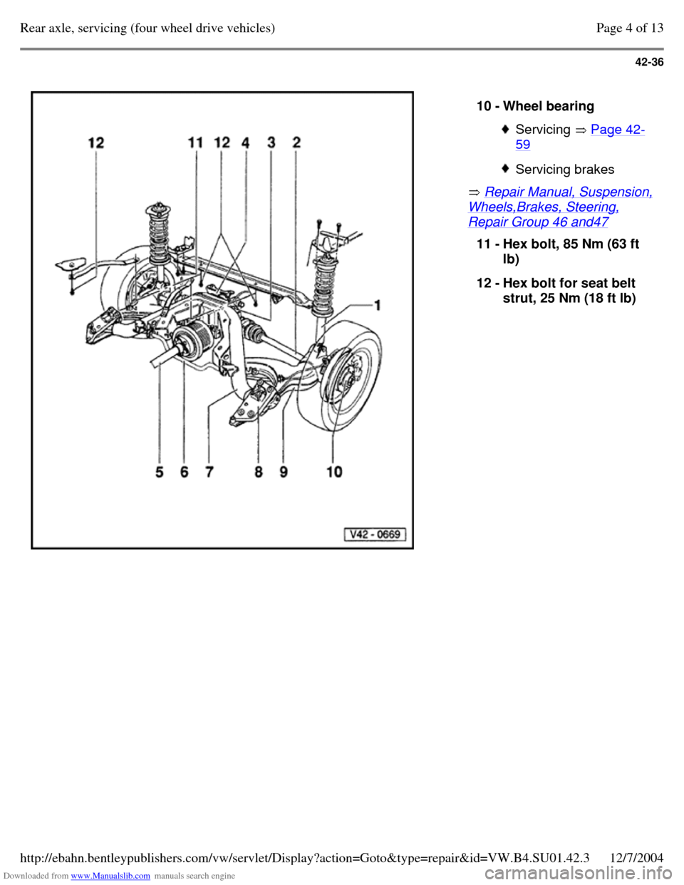
Repair Manual, Suspension, Wheels,Brakes, Steering, Repair Group 46 and47 10 - Wheel bearing Servicing Page 42-59 Servicing brakes 11 - Hex bolt, 85 Nm (63 ft
lb)
12 - Hex bolt for seat belt
strut, 25 Nm (18 ft lb) Page 4 of 13Rear axle, servicing (four wheel drive vehicles)12/7/2004http://ebahn.bentleypublishers.com/vw/servlet/Display?action=Goto&type=repair&id=VW.B4.SU01.42.3
Page 133 of 369
Downloaded from www.Manualslib.com manuals search engine 42-37
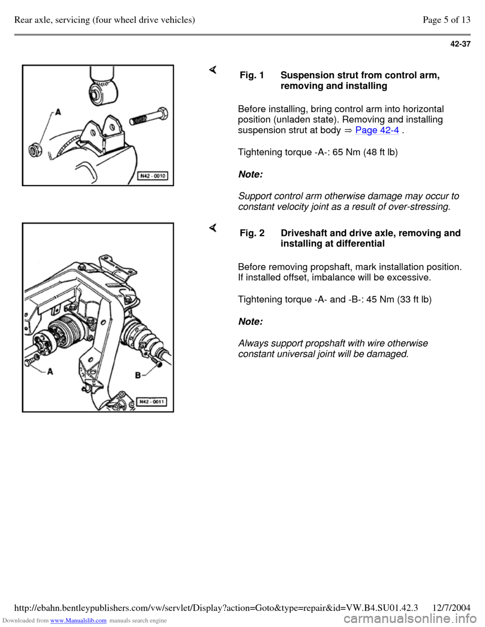
Before installing, bring control arm into horizontal
position (unladen state). Removing and installing
suspension strut at body Page 42-4 .
Tightening torque -A-: 65 Nm (48 ft lb)
Note:
Support control arm otherwise damage may occur to
constant velocity joint as a result of over-stressing. Fig. 1 Suspension strut from control arm,
removing and installing Before removing propshaft, mark installation position.
If installed offset, imbalance will be excessive.
Tightening torque -A- and -B-: 45 Nm (33 ft lb)
Note:
Always support propshaft with wire otherwise
constant universal joint will be damaged. Fig. 2 Driveshaft and drive axle, removing and
installing at differential Page 5 of 13Rear axle, servicing (four wheel drive vehicles)12/7/2004http://ebahn.bentleypublishers.com/vw/servlet/Display?action=Goto&type=repair&id=VW.B4.SU01.42.3
Page 134 of 369
Downloaded from www.Manualslib.com manuals search engine 42-38
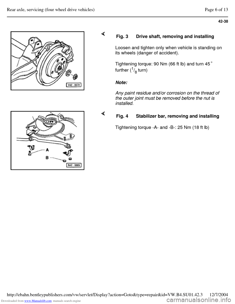
Loosen and tighten only when vehicle is standing on
its wheels (danger of accident).
Tightening torque: 90 Nm (66 ft lb) and turn 45
further (1
/
8 turn)
Note:
Any paint residue and/or corrosion on the thread of
the outer joint must be removed before the nut is
installed. Fig. 3 Drive shaft, removing and installing Tightening torque -A- and -B-: 25 Nm (18 ft lb) Fig. 4 Stabilizer bar, removing and installing Page 6 of 13Rear axle, servicing (four wheel drive vehicles)12/7/2004http://ebahn.bentleypublishers.com/vw/servlet/Display?action=Goto&type=repair&id=VW.B4.SU01.42.3
Page 135 of 369
Downloaded from www.Manualslib.com manuals search engine
Page 136 of 369
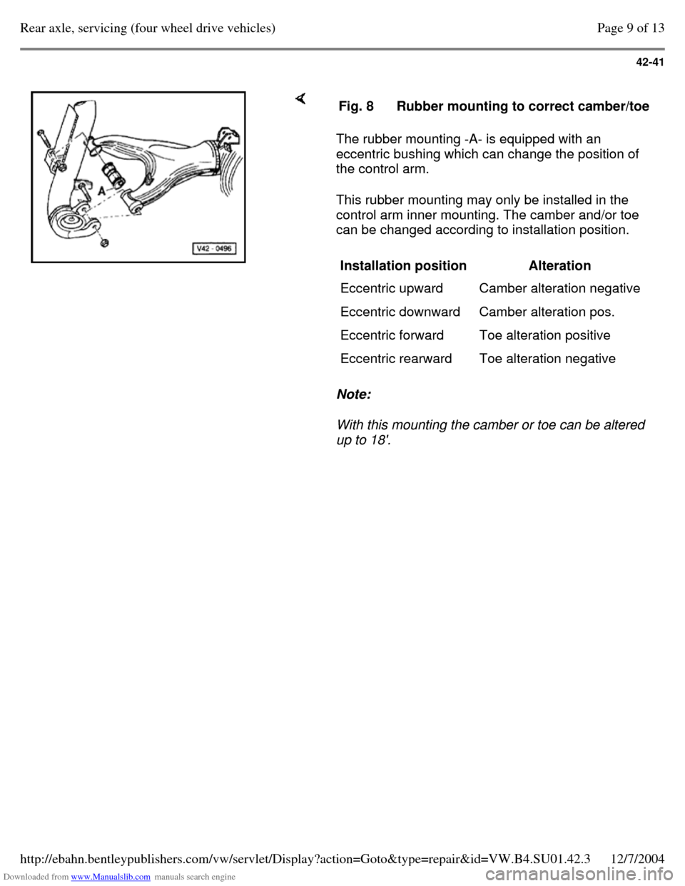
Downloaded from www.Manualslib.com manuals search engine 42-40
Before installing coat with acid free lubricant, e.g. soft
soap.
Installation position: Shoulder on outer mounting to
outside, to inside on inner mounting (to center of
vehicle).
Note:
Deviations from the rear axle toe and camber
specifications can be corrected by using a bonded
rubber mounting with eccentric bushing Fig. 8 Fig. 7 Bonded rubber mounting, installing Page 8 of 13Rear axle, servicing (four wheel drive vehicles)12/7/2004http://ebahn.bentleypublishers.com/vw/servlet/Display?action=Goto&type=repair&id=VW.B4.SU01.42.3
Page 137 of 369
Downloaded from www.Manualslib.com manuals search engine 42-41
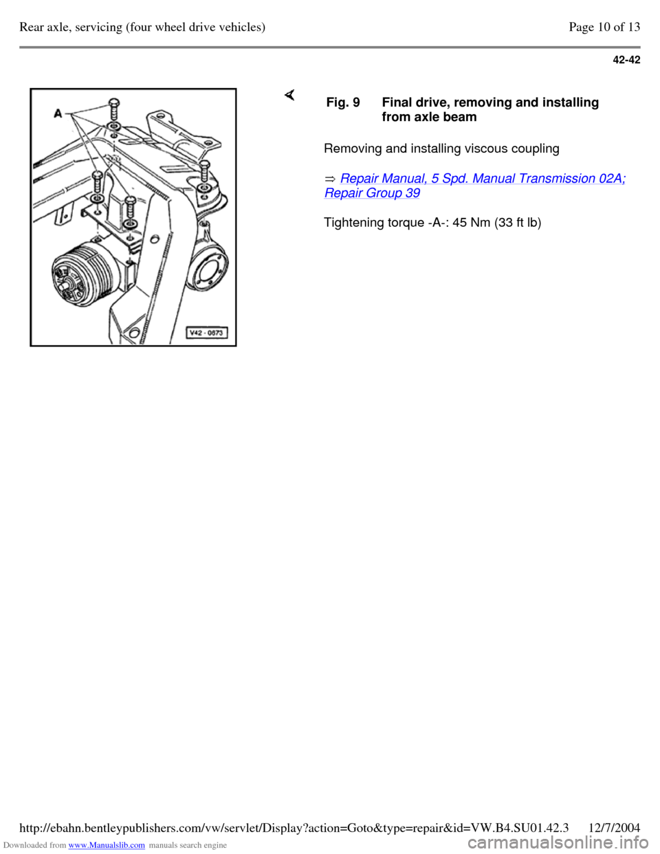
The rubber mounting -A- is equipped with an
eccentric bushing which can change the position of
the control arm.
This rubber mounting may only be installed in the
control arm inner mounting. The camber and/or toe
can be changed according to installation position.
Note:
With this mounting the camber or toe can be altered
up to 18'. Fig. 8 Rubber mounting to correct camber/toe Installation position
Alteration
Eccentric upward Camber alteration negative
Eccentric downward Camber alteration pos.
Eccentric forward Toe alteration positive
Eccentric rearward Toe alteration negative Page 9 of 13Rear axle, servicing (four wheel drive vehicles)12/7/2004http://ebahn.bentleypublishers.com/vw/servlet/Display?action=Goto&type=repair&id=VW.B4.SU01.42.3
Page 138 of 369
Downloaded from www.Manualslib.com manuals search engine 42-42
Removing and installing viscous coupling
Repair Manual, 5 Spd. Manual Transmission 02A; Repair Group 39
Tightening torque -A-: 45 Nm (33 ft lb) Fig. 9 Final drive, removing and installing
from axle beam Page 10 of 13Rear axle, servicing (four wheel drive vehicles)12/7/2004http://ebahn.bentleypublishers.com/vw/servlet/Display?action=Goto&type=repair&id=VW.B4.SU01.42.3
Page 139 of 369
Downloaded from www.Manualslib.com manuals search engine 42-43
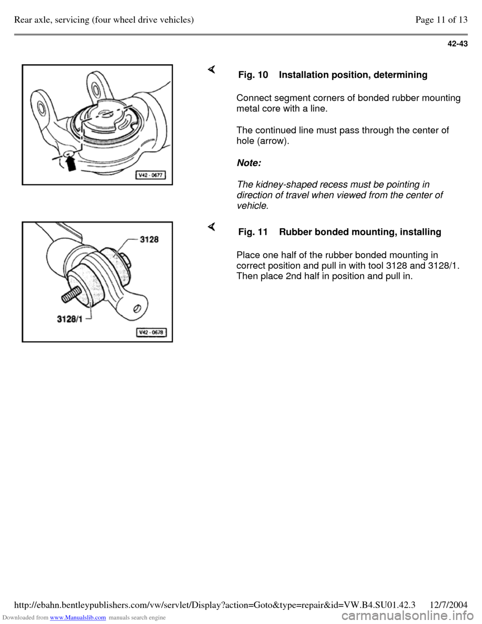
Connect segment corners of bonded rubber mounting
metal core with a line.
The continued line must pass through the center of
hole (arrow).
Note:
The kidney-shaped recess must be pointing in
direction of travel when viewed from the center of
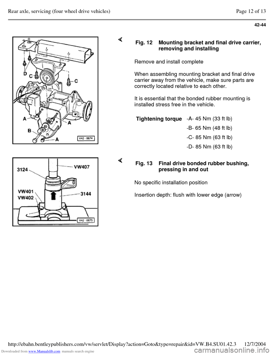
vehicle. Fig. 10 Installation position, determining Place one half of the rubber bonded mounting in
correct position and pull in with tool 3128 and 3128/1.
Then place 2nd half in position and pull in. Fig. 11 Rubber bonded mounting, installing Page 11 of 13Rear axle, servicing (four wheel drive vehicles)12/7/2004http://ebahn.bentleypublishers.com/vw/servlet/Display?action=Goto&type=repair&id=VW.B4.SU01.42.3
Page 140 of 369
Downloaded from www.Manualslib.com manuals search engine 42-44
Remove and install complete
When assembling mounting bracket and final drive
carrier away from the vehicle, make sure parts are
correctly located relative to each other.
It is essential that the bonded rubber mounting is
installed stress free in the vehicle. Fig. 12 Mounting bracket and final drive carrier, removing and installing
Tightening torque -A- 45 Nm (33 ft lb)
-B- 65 Nm (48 ft lb)
-C- 85 Nm (63 ft lb)
-D- 85 Nm (63 ft lb) No specific installation position
Insertion depth: flush with lower edge (arrow) Fig. 13 Final drive bonded rubber bushing,
pressing in and out Page 12 of 13Rear axle, servicing (four wheel drive vehicles)12/7/2004http://ebahn.bentleypublishers.com/vw/servlet/Display?action=Goto&type=repair&id=VW.B4.SU01.42.3
Trending: engine oil, wheel alignment, tow bar, steering wheel, suspension, steering, technical data
