key VOLVO S40 2006 Owners Manual
[x] Cancel search | Manufacturer: VOLVO, Model Year: 2006, Model line: S40, Model: VOLVO S40 2006Pages: 127, PDF Size: 2.26 MB
Page 2 of 127
Your Volvo is designed to meet all applicable safety and emission standards, as indicated by the certification labels
attached to the driver's door opening, and on the underside of the hood.
For further information please contact your retailer, or:
In the USA: Volvo Cars of North America
Customer Care Center
P.O. Box 914 Rockleigh, New Jersey 07647-0914
1-800-458-1552
http://www.volvocars.us
In Canada:Volvo Cars of Canada Ltd.
Customer Care Center
175 Gordon Baker Road
North York, Ontario M2H 2N7
1-800-663-8255
http://www.volvocanada.com
2005 © Volvo Cars of North America, LLC
Introduction
General information
Shiftlock
When your car is parked, the gear selector is locked in the (P)ark position. To release the selector from this position,
turn the ignition key to position II (or start the engine), depress the brake pedal, press the button on the front side of the
gear selector and move the selector from (P)ark.
Keylock
When the ignition is switched off, the gear selector must be in the (P)ark position before the key can be removed from
the ignition switch.
Anti-lock Brake System (ABS)
The ABS system in your car performs a self -diagnostic test when the vehicle first reaches the speed of approximately
12 mph (20 km/h). The brake pedal will pulsate several times and a sound may be audible from the ABS control
module. This is normal.
Fuel filler door
Press the button on the light switch panel when the car is at a standstill to unlock the fuel filler door.
Fuel filler cap
After refueling, close the fuel filler cap by turning it clockwise until it clicks into place. If this cap is not closed tightly
or if the engine is running when the car is refueled, the Malfunction Indicator Lamp ("Check Engine" light) may
indicate a fault.
Points to keep in mind
Before you operate your vehicle for the first time, please familiarize yourself with the new-engine oil consumption
information on page 179
. You should also be familiar with the information found in the chapters "Instruments and
controls", and "Starting and driving".
Information contained in the balance of the manual is extremely useful and should be read after operating the vehicle
for the first time.
The manual is structured so that it can be used for reference. For this reason, it should be kept in the vehicle for
ProCarManuals.com
Page 5 of 127
2 0 0 6
VOLVO S40
Chapter 1 - Instrument overview
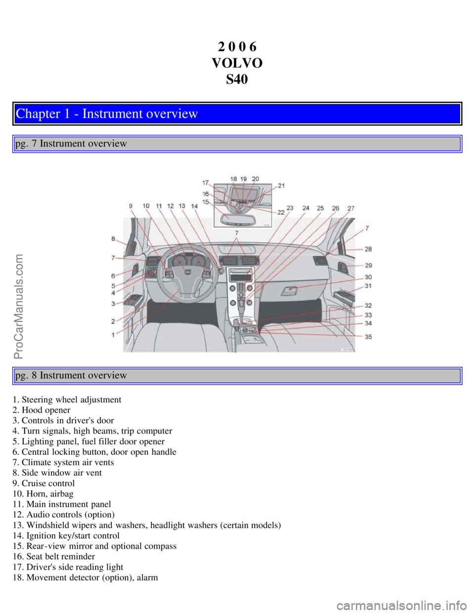
pg. 7 Instrument overview
pg. 8 Instrument overview
1. Steering wheel adjustment
2. Hood opener
3. Controls in driver's door
4. Turn signals, high beams, trip computer
5. Lighting panel, fuel filler door opener
6. Central locking button, door open handle
7. Climate system air vents
8. Side window air vent
9. Cruise control
10. Horn, airbag
11. Main instrument panel
12. Audio controls (option)
13. Windshield wipers and washers, headlight washers (certain models)
14. Ignition key/start control
15. Rear-view mirror and optional compass
16. Seat belt reminder
17. Driver's side reading light
18. Movement detector (option), alarm
ProCarManuals.com
Page 11 of 127
The seat belt reminder reacts if the driver and/or the front seat passenger have not fastened their seat belts.
The indicator light above the mirror and the symbol in the instrument panel will light up and stay lit until the seat
belt(s) have been fastened, or until the remaining 5 minutes of the 6-minute cycle have elapsed.
The chime will sound for 6 seconds, at 30-second intervals. The frequency of the chiming increases with the speed
of the car.
After 6 minutes, the chime will no longer sound and the indicator lights will go out.
Seat belt maintenance
Check periodically that the seat belts are in good condition. Use water and a mild detergent for cleaning. Check seat
belt mechanism function as follows: attach the seat belt and pull rapidly on the strap.
pg. 14 Supplemental Restraint System (SRS)
Supplemental Restraint System
As an enhancement to the three-point seat belts, your Volvo is equipped with a Supplemental Restraint System (SRS).
Volvo's SRS consists of seat belt tensioners, front airbags, side impact airbags, the occupant weight sensor, and
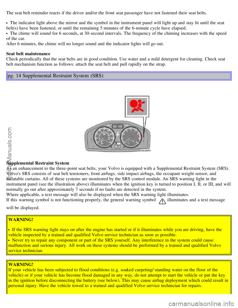
inflatable curtains. All of these systems are monitored by the SRS control module. An SRS warning light in the
instrument panel (see the illustration above) illuminates when the ignition key is turned to position I, II, or III, and will
normally go out after approximately 7 seconds if no faults are detected in the system.
Where applicable, a text message will also be displayed when the SRS warning light illuminates.
If this warning symbol is not functioning properly, the general warning symbol
illuminates and a text message
will be displayed.
WARNING!
If the SRS warning light stays on after the engine has started or if it illuminates while you are driving, have the
vehicle inspected by a trained and qualified Volvo service technician as soon as possible.
Never try to repair any component or part of the SRS yourself. Any interference in the system could cause
malfunction and serious injury. All work on these systems should be performed by a trained and qualified Volvo
service technician.
WARNING!
If your vehicle has been subjected to flood conditions (e.g. soaked carpeting/ standing water on the floor of the
vehicle) or if your vehicle has become flood damaged in any way, do not attempt to start the vehicle or put the key
in the ignition before disconnecting the battery (see below). This may cause airbag deployment which could result in
personal injury. Have the vehicle towed to a trained and qualified Volvo service technician for repairs.
ProCarManuals.com
Page 12 of 127
Automatic transmission:
Before attempting to tow the vehicle, use the following procedure to override the shiftlock system to move the gear
selector to the neutral position:
Switch off the ignition for at least 10 minutes and disconnect the battery
Wait at least one minute.
Insert the key in the ignition and turn it to position II.
Press firmly on the brake pedal.
Move the gear selector from (P)ark to the (N)eutral position. See page 105 for information on manually overriding
the shiftlock system.
pg. 15 Front airbags
Front airbags
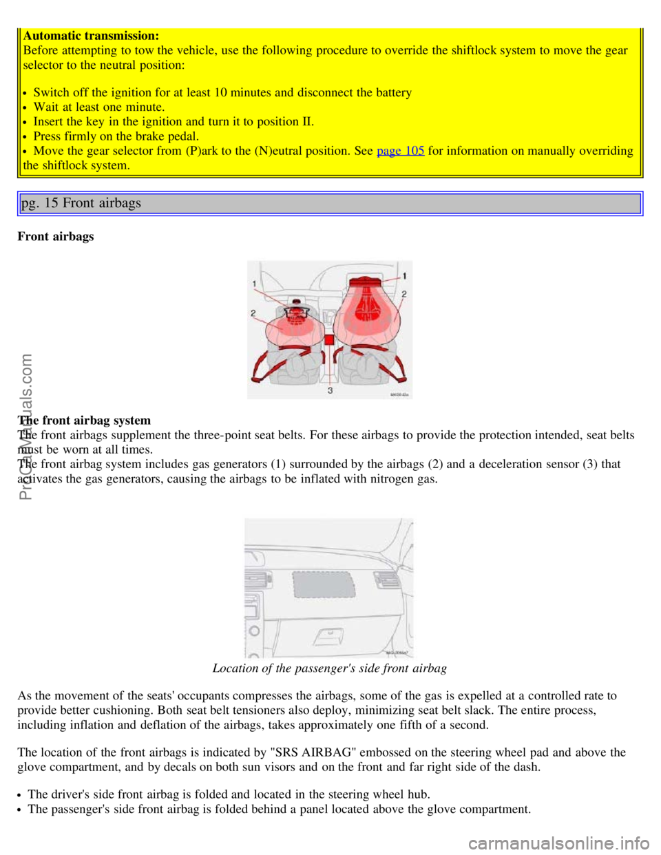
The front airbag system
The front airbags supplement the three-point seat belts. For these airbags to provide the protection intended, seat belts
must be worn at all times.
The front airbag system includes gas generators (1) surrounded by the airbags (2) and a deceleration sensor (3) that
activates the gas generators, causing the airbags to be inflated with nitrogen gas.
Location of the passenger's side front airbag
As the movement of the seats' occupants compresses the airbags, some of the gas is expelled at a controlled rate to
provide better cushioning. Both seat belt tensioners also deploy, minimizing seat belt slack. The entire process,
including inflation and deflation of the airbags, takes approximately one fifth of a second.
The location of the front airbags is indicated by "SRS AIRBAG" embossed on the steering wheel pad and above the
glove compartment, and by decals on both sun visors and on the front and far right side of the dash.
The driver's side front airbag is folded and located in the steering wheel hub.
The passenger's side front airbag is folded behind a panel located above the glove compartment.
ProCarManuals.com
Page 20 of 127
14. Temperature gauge
The gauge indicates the temperature of the engine cooling system. If the temperature is abnormally high and the needle
enters the red zone, a message is shown in the display. Bear in mind that auxiliary lamps in front of the air intake
reduce the cooling capacity at high outside temperatures and high engine loads.
15. Indicator and warning symbols
1. Models with All Wheel Drive have a tank volume of 15 US gallons (57 liters).
Models with engine code 39 have a fuel tank capacity of 14 US gallons (53 liters). This code is the 6th and 7th digits
from the left in your vehicle's VIN number. See page 176
for the location of the VIN plate.
pg. 35 Indicator and warning symbols
Function check
The indicator and warning symbols light up when you turn the ignition key to the driving position (position II) before
starting. This shows that the symbols are functioning. When the engine starts, all symbols go out. If the engine is not
started within 5 seconds, all of the symbols except CHECK ENGINE and
will go out. Certain symbols may not
have their functions illustrated, depending on the car's equipment. The PARK BRAKE symbol will not go out until the
parking brake has been released.
Symbols in the center of the instrument panel
Warning symbol
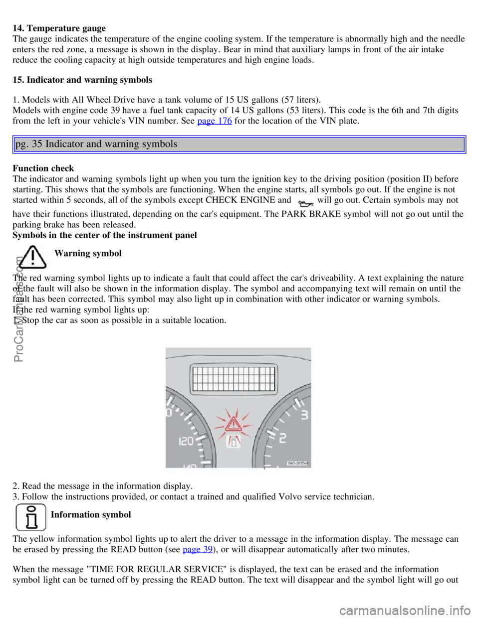
The red warning symbol lights up to indicate a fault that could affect the car's driveability. A text explaining the nature
of the fault will also be shown in the information display. The symbol and accompanying text will remain on until the
fault has been corrected. This symbol may also light up in combination with other indicator or warning symbols.
If the red warning symbol lights up:
1. Stop the car as soon as possible in a suitable location.
2. Read the message in the information display.
3. Follow the instructions provided, or contact a trained and qualified Volvo service technician.
Information symbol
The yellow information symbol lights up to alert the driver to a message in the information display. The message can
be erased by pressing the READ button (see page 39
), or will disappear automatically after two minutes.
When the message "TIME FOR REGULAR SERVICE" is displayed, the text can be erased and the information
symbol light can be turned off by pressing the READ button. The text will disappear and the symbol light will go out
ProCarManuals.com
Page 25 of 127
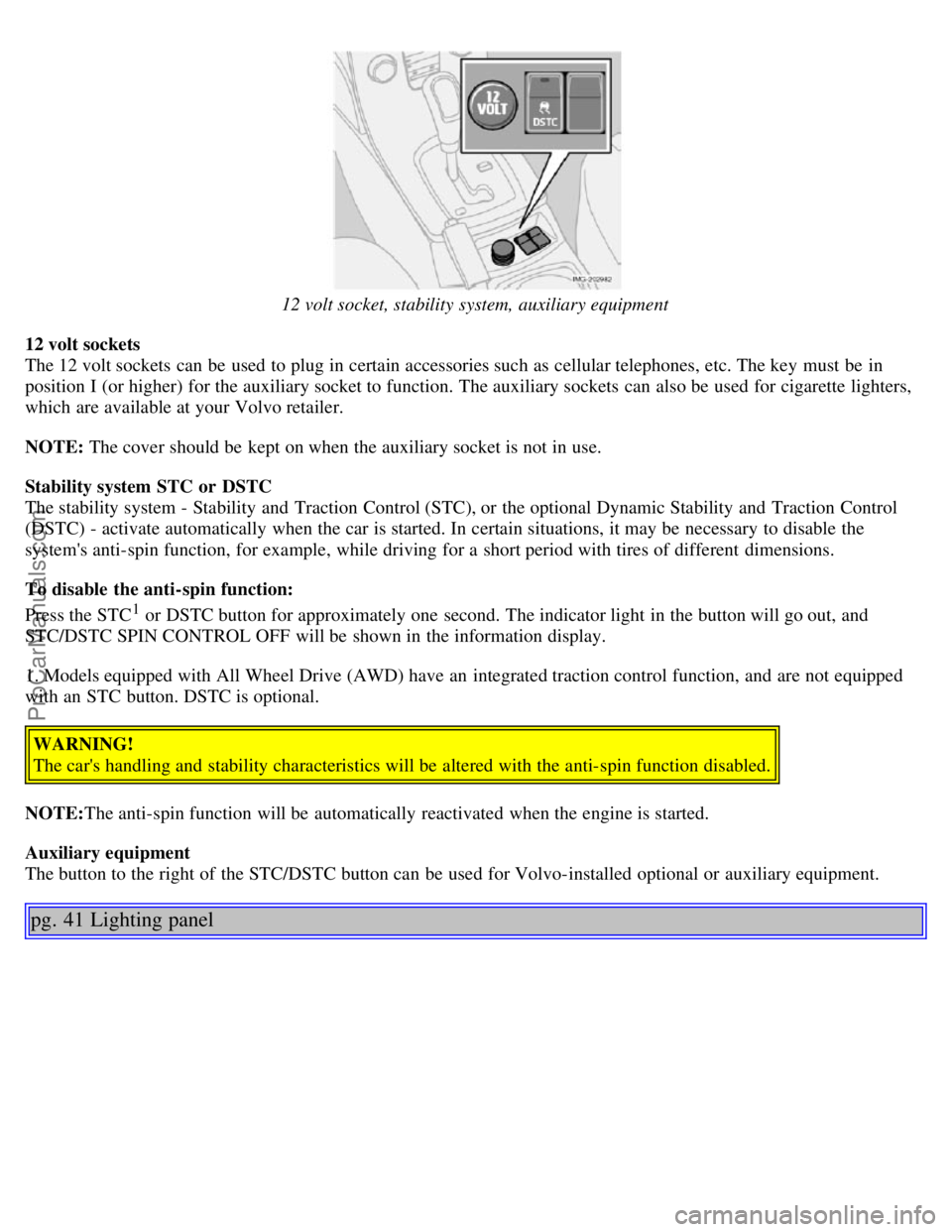
12 volt socket, stability system, auxiliary equipment
12 volt sockets
The 12 volt sockets can be used to plug in certain accessories such as cellular telephones, etc. The key must be in
position I (or higher) for the auxiliary socket to function. The auxiliary sockets can also be used for cigarette lighters,
which are available at your Volvo retailer.
NOTE: The cover should be kept on when the auxiliary socket is not in use.
Stability system STC or DSTC
The stability system - Stability and Traction Control (STC), or the optional Dynamic Stability and Traction Control
(DSTC) - activate automatically when the car is started. In certain situations, it may be necessary to disable the
system's anti-spin function, for example, while driving for a short period with tires of different dimensions.
To disable the anti-spin function:
Press the STC
1 or DSTC button for approximately one second. The indicator light in the button will go out, and
STC/DSTC SPIN CONTROL OFF will be shown in the information display.
1. Models equipped with All Wheel Drive (AWD) have an integrated traction control function, and are not equipped
with an STC button. DSTC is optional.
WARNING!
The car's handling and stability characteristics will be altered with the anti-spin function disabled.
NOTE: The anti-spin function will be automatically reactivated when the engine is started.
Auxiliary equipment
The button to the right of the STC/DSTC button can be used for Volvo-installed optional or auxiliary equipment.
pg. 41 Lighting panel
ProCarManuals.com
Page 26 of 127
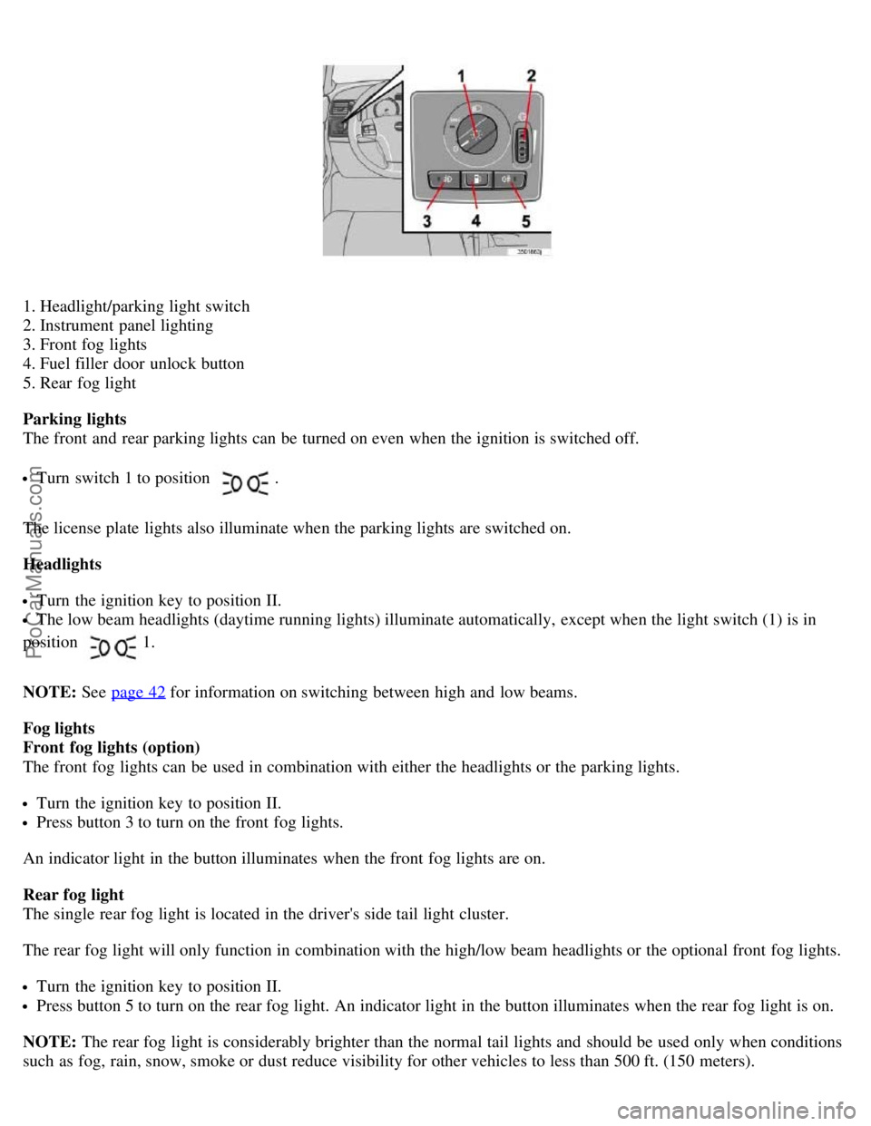
1. Headlight/parking light switch
2. Instrument panel lighting
3. Front fog lights
4. Fuel filler door unlock button
5. Rear fog light
Parking lights
The front and rear parking lights can be turned on even when the ignition is switched off.
Turn switch 1 to position .
The license plate lights also illuminate when the parking lights are switched on.
Headlights
Turn the ignition key to position II.
The low beam headlights (daytime running lights) illuminate automatically, except when the light switch (1) is in
position
1.
NOTE: See page 42
for information on switching between high and low beams.
Fog lights
Front fog lights (option)
The front fog lights can be used in combination with either the headlights or the parking lights.
Turn the ignition key to position II.
Press button 3 to turn on the front fog lights.
An indicator light in the button illuminates when the front fog lights are on.
Rear fog light
The single rear fog light is located in the driver's side tail light cluster.
The rear fog light will only function in combination with the high/low beam headlights or the optional front fog lights.
Turn the ignition key to position II.
Press button 5 to turn on the rear fog light. An indicator light in the button illuminates when the rear fog light is on.
NOTE: The rear fog light is considerably brighter than the normal tail lights and should be used only when conditions
such as fog, rain, snow, smoke or dust reduce visibility for other vehicles to less than 500 ft. (150 meters).
ProCarManuals.com
Page 27 of 127
Instrument panel lighting
The instrument panel lighting illuminates when the ignition key is in position II and the light switch (1) is in either
position
or .
Move the thumb wheel (2) up to increase brightness or down to decrease brightness.
Unlocking the fuel filler door
With the ignition switched off, press button 4 to unlock the fuel filler door. Please note that the fuel filler door will
remain unlocked until the car begins to move forward.
An audible click will be heard when the fuel filler door re-locks.
1. On Canadian models, the daytime running lights will remain on with the light switch in this position.
pg. 42 Left-side steering wheel lever
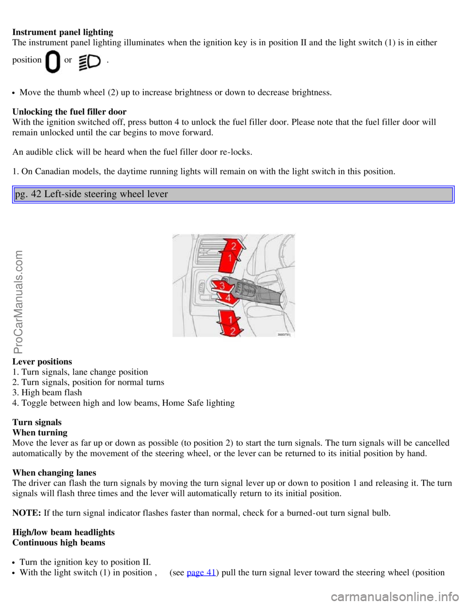
Lever positions
1. Turn signals, lane change position
2. Turn signals, position for normal turns
3. High beam flash
4. Toggle between high and low beams, Home Safe lighting
Turn signals
When turning
Move the lever as far up or down as possible (to position 2) to start the turn signals. The turn signals will be cancelled
automatically by the movement of the steering wheel, or the lever can be returned to its initial position by hand.
When changing lanes
The driver can flash the turn signals by moving the turn signal lever up or down to position 1 and releasing it. The turn
signals will flash three times and the lever will automatically return to its initial position.
NOTE: If the turn signal indicator flashes faster than normal, check for a burned-out turn signal bulb.
High/low beam headlights
Continuous high beams
Turn the ignition key to position II.
With the light switch (1) in position , (see page 41) pull the turn signal lever toward the steering wheel (position
ProCarManuals.com
Page 28 of 127
4) to toggle between high and low beams.
High beam flash
Turn the ignition key to position II.
Pull the turn signal lever to position 3. The high beams will remain on until the lever is released.
Home safe lighting
When you leave your car at night, you can make use of the home safe lighting function to illuminate the area in front
of the car.
Remove the key from the ignition switch.
Pull the direction indicator lever as far as possible towards the steering wheel (to position 4) and release it.
Exit the car and lock the doors.
The headlights and parking lights will illuminate and remain on for 30
1, 60 or 90 seconds. The time interval can be
changed according to your preferences by using the Personal Settings function, see page 56
for more information.
1. Factory setting
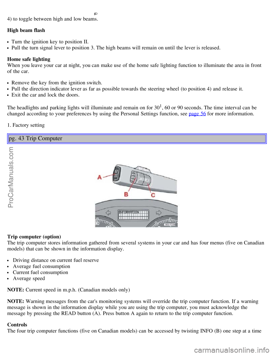
pg. 43 Trip Computer
Trip computer (option)
The trip computer stores information gathered from several systems in your car and has four menus (five on Canadian
models) that can be shown in the information display.
Driving distance on current fuel reserve
Average fuel consumption
Current fuel consumption
Average speed
NOTE: Current speed in m.p.h. (Canadian models only)
NOTE: Warning messages from the car's monitoring systems will override the trip computer function. If a warning
message is shown in the information display while you are using the trip computer, you must acknowledge the
message by pressing the READ button (A). Press button A again to return to the trip computer function.
Controls
The four trip computer functions (five on Canadian models) can be accessed by twisting INFO (B) one step at a time
ProCarManuals.com
Page 33 of 127
The rain sensor is automatically deactivated:
When the key is removed from the ignition.
Five minutes after the ignition is switched off if the key is left in the ignition.
C - Thumb wheel
The thumb wheel is used to set the wiper interval when intermittent wiping is selected, or the sensitivity to the amount
of rain on the windshield when the rain sensor is selected. Move the wheel upward or downward to increase/decrease
wiper speed when the intermittent function is selected, or to increase/decrease the optional rain sensor's sensitivity
when the this function is activated.
D - This button is used on wagon models only
Contents | Top of Page
ProCarManuals.com