My Car VOLVO S60 2018 Owner´s Manual
[x] Cancel search | Manufacturer: VOLVO, Model Year: 2018, Model line: S60, Model: VOLVO S60 2018Pages: 396, PDF Size: 9.4 MB
Page 332 of 396

||
MAINTENANCE AND SERVICING
330
Checking and adding oil
G021734
Location of the filler cap and dipstick
NOTE
Before checking the oil:
• The car should be parked on a level sur- face.
• If the engine is warm
, wait for at least
10 – 15 minutes after the engine hasbeen switched off.
G021737
The oil level must be between the MIN and MAX marks
on the dipstick
Checking the oil
1. Pull out the dipstick and wipe it with a lint-
free rag.
2. Reinsert the dipstick, pull it out, and check the oil level. The level must be between the MIN and MAX marks.
3. Add oil if necessary. If the level is close to the MIN mark, add approximately
0.5 US quarts (0.5 liters) of oil.
4. Recheck the level and add more oil if neces- sary until the level is near the MAX mark.
WARNING
Do not allow oil to spill onto or come into con- tact with hot exhaust pipe surfaces.
Electronic oil level sensor (4-cylinder engines only)
Oil filler cap
No action is necessary until a message is dis- played, see the following illustration.
Page 335 of 396
MAINTENANCE AND SERVICING
}}
333
Engine compartment – brake fluid
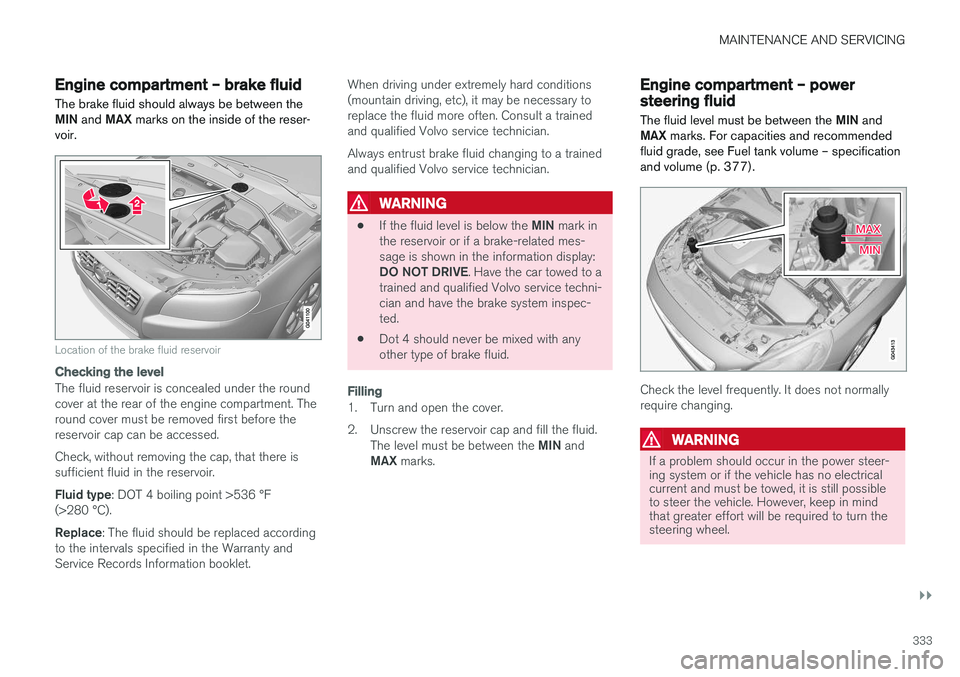
The brake fluid should always be between the MIN and MAX marks on the inside of the reser-
voir.
Location of the brake fluid reservoir
Checking the level
The fluid reservoir is concealed under the round cover at the rear of the engine compartment. Theround cover must be removed first before thereservoir cap can be accessed. Check, without removing the cap, that there is sufficient fluid in the reservoir. Fluid type : DOT 4 boiling point >536 °F
(>280 °C).Replace : The fluid should be replaced according
to the intervals specified in the Warranty and Service Records Information booklet. When driving under extremely hard conditions(mountain driving, etc), it may be necessary toreplace the fluid more often. Consult a trainedand qualified Volvo service technician. Always entrust brake fluid changing to a trained and qualified Volvo service technician.
WARNING
•
If the fluid level is below the
MIN mark in
the reservoir or if a brake-related mes- sage is shown in the information display: DO NOT DRIVE . Have the car towed to a
trained and qualified Volvo service techni- cian and have the brake system inspec-ted.
• Dot 4 should never be mixed with anyother type of brake fluid.
Filling
1. Turn and open the cover.
2. Unscrew the reservoir cap and fill the fluid.
The level must be between the MIN and
MAX marks.
Engine compartment – power steering fluid
The fluid level must be between the MIN and
MAX marks. For capacities and recommended
fluid grade, see Fuel tank volume – specification and volume (p. 377).
Check the level frequently. It does not normally require changing.
WARNING
If a problem should occur in the power steer- ing system or if the vehicle has no electricalcurrent and must be towed, it is still possibleto steer the vehicle. However, keep in mindthat greater effort will be required to turn thesteering wheel.
Page 342 of 396

MAINTENANCE AND SERVICING
340
Bulbs – taillight housing The bulbs in the taillight cluster are replaced from inside the trunk (not the LED functions).
NOTE
Before starting to replace a bulb, see Bulbs – introduction (p. 334).
1. Remove the covers in the left/right panel toaccess the bulb holder.
2. Press the catches together and pull out the bulb holder.
3. Remove the defective bulb by pressing it in slightly and it turning counterclockwise before pulling it out.
4. Insert a new bulb, press it in slightly and turn it clockwise. 5. Press the bulb holder back into place and
reinstall the cover.
Related information
• Bulbs – introduction (p. 334)
• Bulbs – location of taillight bulbs (p. 339)
• Bulbs – specifications (p. 341)
Bulbs – license plate lighting
The license plate lighting is located next to the trunk handle.
1. Remove the screws with a screwdriver.
2. Carefully detach the entire bulb housing and pull it out.
3. Replace the bulb.
4. Reinsert the entire bulb housing and tighten the screws.
Related information
• Bulbs – specifications (p. 341)
Page 343 of 396
MAINTENANCE AND SERVICING
}}
* Option/accessory.341
Bulbs – trunk lighting
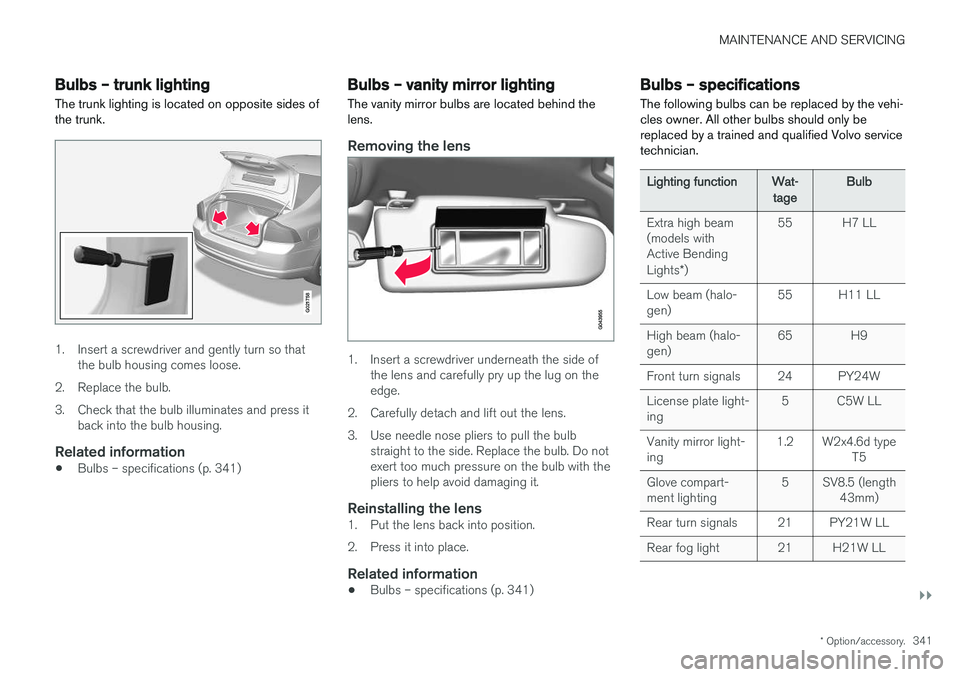
The trunk lighting is located on opposite sides of the trunk.
G021758
1. Insert a screwdriver and gently turn so that the bulb housing comes loose.
2. Replace the bulb.
3. Check that the bulb illuminates and press it back into the bulb housing.
Related information
• Bulbs – specifications (p. 341)
Bulbs – vanity mirror lighting
The vanity mirror bulbs are located behind the lens.
Removing the lens
1. Insert a screwdriver underneath the side of the lens and carefully pry up the lug on the edge.
2. Carefully detach and lift out the lens.
3. Use needle nose pliers to pull the bulb straight to the side. Replace the bulb. Do not exert too much pressure on the bulb with thepliers to help avoid damaging it.
Reinstalling the lens1. Put the lens back into position.
2. Press it into place.
Related information
• Bulbs – specifications (p. 341)
Bulbs – specifications The following bulbs can be replaced by the vehi- cles owner. All other bulbs should only bereplaced by a trained and qualified Volvo servicetechnician.
Lighting function
Wat-
tage Bulb
Extra high beam (models withActive Bending Lights *) 55 H7 LL
Low beam (halo- gen) 55 H11 LL
High beam (halo-gen) 65 H9
Front turn signals 24 PY24W License plate light- ing 5 C5W LL
Vanity mirror light-ing 1.2 W2x4.6d type
T5
Glove compart-ment lighting 5 SV8.5 (length
43mm)
Rear turn signals 21 PY21W LL
Rear fog light 21 H21W LL
Page 350 of 396

||
MAINTENANCE AND SERVICING
* Option/accessory.
348
Removal
Switch off the ignition, remove the remote key from the ignition slot and wait at least 5 minutesbefore disconnecting the battery so that all infor-mation in the vehicle's electrical system can bestored in the control modules.
Open the clips on the front cover and remove the cover.
Release the rubber molding so that the rear cover is free.
Remove the rear cover by pulling it away.
Detach the black negative cable.
Detach the red positive cable
Detach the ventilation hose from the bat-
tery
Loosen the screw holding the battery
clamp.
Move the battery to the side and lift it up.
WARNING
PROPOSITION 65 WARNING! Battery posts, terminals, and related accesso- ries contain lead and lead compounds, chemi-cals known to the state of California to causecancer and reproductive harm. Wash handsafter handling.
Rally bar R-Design models *
Rally bar and bulkhead hatch
Vehicles with the optional R-Design package are equipped with a rally bar in the engine compart-ment that must be removed before the batterycan be replaced.
1. Remove the hatch in the bulkhead on both
sides of the engine compartment (pry them up carefully with a plastic knife or similarobject).
2. Remove the screw on each side of the engine compartment holding the rally bar inplace.
3. Lift out the rally bar. > The battery can now be removed (see theinstructions in the previous section). •
After a new battery has been installed (seethe following section), reinstall the rally bar inthe reverse order.
NOTE
When reinstalling the rally bar, tighten the screws to 22 ft lbs (30 Nm).
Page 354 of 396
||
MAINTENANCE AND SERVICING
352
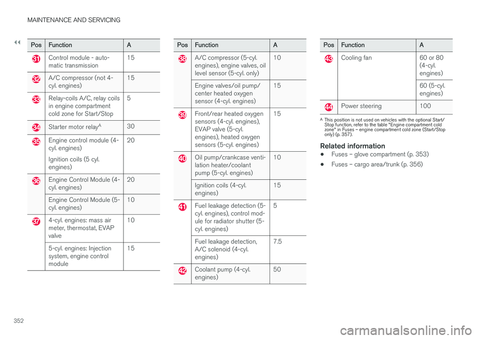
PosFunction A
Control module - auto- matic transmission15
A/C compressor (not 4- cyl. engines)15
Relay-coils A/C, relay coils in engine compartmentcold zone for Start/Stop5
Starter motor relay
A
30
Engine control module (4- cyl. engines) Ignition coils (5 cyl. engines) 20
Engine Control Module (4- cyl. engines)
20
Engine Control Module (5-cyl. engines) 10
4-cyl. engines: mass air meter, thermostat, EVAPvalve10
5-cyl. engines: Injectionsystem, engine controlmodule 15
Pos
Function A
A/C compressor (5-cyl. engines), engine valves, oillevel sensor (5-cyl. only)10
Engine valves/oil pump/center heated oxygensensor (4-cyl. engines) 15
Front/rear heated oxygen sensors (4-cyl. engines),EVAP valve (5-cyl.engines), heated oxygensensors (5-cyl. engines)15
Oil pump/crankcase venti- lation heater/coolantpump (5-cyl. engines)
10
Ignition coils (4-cyl.engines) 15
Fuel leakage detection (5- cyl. engines), control mod-ule for radiator shutter (5-cyl. engines)5
Fuel leakage detection,A/C solenoid (4-cyl.engines) 7.5
Coolant pump (4-cyl. engines)
50
Pos
Function A
Cooling fan 60 or 80
(4-cyl. engines) 60 (5-cyl. engines)
Power steering 100
AThis position is not used on vehicles with the optional Start/ Stop function, refer to the table "Engine compartment coldzone" in Fuses – engine compartment cold zone (Start/Stoponly) (p. 357).
Related information
• Fuses – glove compartment (p. 353)
• Fuses – cargo area/trunk (p. 356)
Page 357 of 396
MAINTENANCE AND SERVICING
* Option/accessory.355
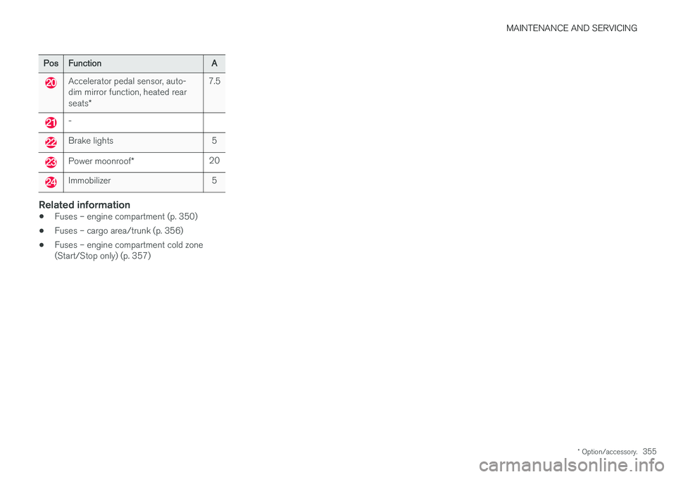
PosFunction A
Accelerator pedal sensor, auto- dim mirror function, heated rear seats* 7.5
-
Brake lights 5
Power moonroof
* 20
Immobilizer 5
Related information
•Fuses – engine compartment (p. 350)
• Fuses – cargo area/trunk (p. 356)
• Fuses – engine compartment cold zone (Start/Stop only) (p. 357)
Page 358 of 396

MAINTENANCE AND SERVICING
* Option/accessory.
356
Fuses – cargo area/trunk The fuses in the cargo area/trunk protect com- ponents such as trailer connections, the parkingbrake, etc.
Located behind the upholstery on the left side of the trunk
Positions
Pos Function A
Electric parking brake (left side) 30
Electric parking brake (right side) 30
Heated rear window 30
Trailer socket 2* 15
-
Pos
Function A
12-volt socket in trunk 15
-
-
-
-
PosFunction A
Trailer socket 1* 40
-
Related information
•Fuses – engine compartment (p. 350)
• Fuses – glove compartment (p. 353)
• Fuses – engine compartment cold zone (Start/Stop only) (p. 357)
Page 360 of 396

||
MAINTENANCE AND SERVICING
358
PosFunction A
Circuit breaker: fusebox A under
the glove compartment (see Fuses – glove compartment(p. 353)) 60
Circuit breaker: fusebox
A under
the glove compartment (see Fuses – glove compartment(p. 353)) 60
Circuit breaker: central electrical module in the trunk
60
Climate system blower 40
– –
– –
Starter motor relay 30
Internal diode 50
Auxiliary battery 70
Central electrical module: auxili- ary battery reference voltage,auxiliary battery charging point15
Related information
•
Fuses – engine compartment (p. 350)
• Fuses – glove compartment (p. 353) •
Fuses – cargo area/trunk (p. 356)
• Start/Stop – introduction (p. 260)
Page 361 of 396
MAINTENANCE AND SERVICING
}}
* Option/accessory.359
Washing the vehicle
The vehicle should be washed at regular inter- vals since dirt, dust, insects and tar spotsadhere to the paint and may cause damage. Tohelp prevent corrosion, it is particularly importantto wash the car frequently in the wintertime.
The following points should be kept in mind when washing and cleaning the car:
CAUTION
Avoid using car washing detergents with a pH value lower than 3.5 or higher than 11.5.Doing so could result in discoloring of ano-dized aluminum surfaces on e.g., roof rails orthe frames around the side windows.
• Avoid washing your car in direct sunlight. Doing so may cause detergents and wax todry out and become abrasive. To avoidscratching, use lukewarm water to soften thedirt before you wash with a soft sponge, andplenty of sudsy water.
• Bird droppings
: Remove from paintwork as
soon as possible. Otherwise the finish maybe permanently damaged.
• A detergent can be used to facilitate thesoftening of dirt and oil.
• Dry the car with a clean chamois andremember to clean the drain holes in thedoors and rocker panels. •
Tar spots can be removed with tar removerafter the car has been washed.
• A stiff-bristle brush and lukewarm soapywater can be used to clean the wiper blades.Frequent cleaning of the windshield andwiper blades improves visibility considerablyand also helps prolong the service life of thewiper blades.
• Wash off the dirt from the underside (wheelhousings, fenders, etc).
• In areas of high industrial fallout, more fre-quent washing is recommended.
NOTE
When washing the vehicle, remember to remove dirt from the drain holes in the doorsand sills.
CAUTION
•
During high pressure washing, the spray mouthpiece must never be closer to thevehicle than 13" (30 cm). Do not sprayinto the locks.
• Dirt, snow, etc., on the headlights canreduce lighting capacity considerably.Clean the headlights regularly, for exam-ple when refueling.
Special moonroof cautions:
• Always close the moonroof and sunshade before washing your vehicle.
• Never use abrasive cleaning agents onthe moonroof.
• Never use wax on the rubber sealsaround the moonroof.
Exterior componentsVolvo recommends the use of special cleaning products, available at your Volvo retailer, forcleaning colored plastic, rubber, or ornamentalcomponents such as chromed strips on the exte-rior of your vehicle. The instructions for usingthese products should be followed carefully. Sol-vents or stain removers should not be used. The frames around the side windows, roof rails and door frames near the windows
* are made of
anodized aluminum and should only be washed