My Car VOLVO S60 2018 Owner´s Manual
[x] Cancel search | Manufacturer: VOLVO, Model Year: 2018, Model line: S60, Model: VOLVO S60 2018Pages: 396, PDF Size: 9.4 MB
Page 295 of 396

WHEELS AND TIRES
}}
* Option/accessory.293
Changing a wheel – direction of rotation Incorrectly mounted tires impair the car's braking properties and ability to force aside rain, snowand slush.
Summer and winter tires
G021778
The arrows shows the direction of rotation of the tire
•The tires with the most tread should always be on the rear axle (to help reduce the risk ofskidding).
• When switching between summer and wintertires, mark the tires to indicate where theywere mounted on the car, e.g., LF = left front,RR = right rear
• Tires with tread designed to roll in only onedirection are marked with an arrow on thesidewall.
• Contact a Volvo workshop if you are unsureabout the tread depth.
Related information
•Tire specifications (p. 300)
• Tires – storage and age (p. 291)
• Tires – tread wear indicator (p. 292)
Changing a wheel – removing wheel Wheel changes should always be carried out correctly.
The jack
*, towing eyelet and tools * are stowed
under the floor of the trunk.
Changing a wheel1. Apply the parking brake and put the gear
selector in P.
2. Take out the jack *, lug wrench *, the tool for
removing the plastic covers on the wheel nuts, the towing eyelet and the wheel coverremoval tool (certain models only) stowedunder the floor of the trunk.
Page 298 of 396

WHEELS AND TIRES
* Option/accessory.
296
Changing a wheel – spare wheel Wheel changes should always be carried out correctly.
Spare tireA spare tire can be purchased for your vehicle as an accessory. Follow the instructions includedwith the spare tire regarding use and stowing inthe vehicle. See also Changing a wheel – remov-ing wheel (p. 293) for additional information.
Spare wheelThe following instructions only apply if you have purchased a temporary spare wheel * for your
vehicle. If there is no temporary spare wheel in your vehi- cle, please see Tire sealing system * – general
information (p. 314) for instructions on using the tire sealing system. The accessory temporary spare wheel is provided in a bag that must be securely strapped in placein the trunk while the vehicle is being driven. The spare wheel is only intended for temporary use. Replace it with a normal wheel as soon aspossible. The vehicle's handling may be alteredby the use of the spare wheel. The correct tirepressure is stated in the tire pressure table, seethe tire inflation decal on the driver's door open-ing.Turn the handle on the spare wheel bag in toward the rear seat. Secure the stitched straphooks in the loading eyelets. Secure the longstrap in one of the loading eyelets, wrap the straparound the spare wheel and through the lowerhandle. Secure the short strap on the long strap.Secure in the other loading eyelet and tighten.
WARNING
Current legislation prohibits the use of the “Temporary Spare” tire other than as a tempo-rary replacement for a punctured tire. It mustbe replaced as soon as possible by a stand-ard tire. Road holding and handling may beaffected with the “Temporary Spare” in use.
CAUTION
The vehicle must never be driven with more than one temporary spare wheel.
Related information
• Changing a wheel – installing a wheel (p. 297)
• Changing a wheel – removing wheel (p. 293)
Page 299 of 396

WHEELS AND TIRES
}}
* Option/accessory.297
Changing a wheel – accessing the spare wheel
The following procedure explains how to access the spare wheel (where applicable).
1. Release the bag's retaining straps.
2. Lift the bag out of the vehicle and remove the spare wheel from the bag.
3. Fold up the floor hatch in the trunk.4. Remove the jack * and tools * from the foam
block and change the wheels (see the instructions in the following section "Chang-ing a wheel").
5. After changing wheels, return the jack and tools to the foam block and close the floorhatch.
6. If possible, place the wheel with the punc- tured tire in the bag. 7. If there is a wheel in the bag, strap the bag
securely in place in the trunk.
WARNING
•If there is a wheel in the bag, the bag must be securely restrained using its straps andthe load anchoring eyelets in the trunk.See (p. 296) and carefully follow theinstructions.
• If the wheel with the punctured tire is toobig to fit in the bag, it should be securelyrestrained in the trunk using suitablestraps, a net for anchoring cargo, etc.
Changing a wheel – installing a wheel
It is important to re-install wheels properly.
Re-installing the wheel1. Clean the contact surfaces on the wheel and hub.
2. Lift the wheel and place it on the hub.
Tighten the wheel nuts
3. Install the wheel nuts and tighten hand-tight. Using the lug wrench, tighten crosswise until all nuts are snug.
4. Lower the vehicle to the ground and alter- nately tighten the bolts crosswise to103 ft. lbs. (140 Nm).
Page 300 of 396
||
WHEELS AND TIRES
2985. Press the plastic covers onto the wheel nuts
and Install the wheel cover (where applica- ble). The opening in the wheel cover for thetire's inflation valve must be positioned overthe valve.
Related information
• Changing a wheel – spare wheel (p. 296)
• Changing a wheel – removing wheel (p. 293)
Tire inflation – general information
Check tire inflation pressure regularly.
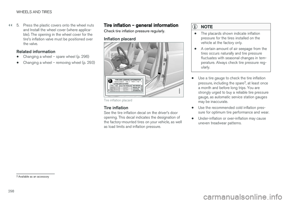
Inflation placard
G032521
Tire inflation placard
Tire inflationSee the tire inflation decal on the driver's door opening. This decal indicates the designation ofthe factory-mounted tires on your vehicle, as wellas load limits and inflation pressure.
NOTE
• The placards shown indicate inflation pressure for the tires installed on thevehicle at the factory only.
• A certain amount of air seepage from thetires occurs naturally and tire pressurefluctuates with seasonal changes in tem-perature. Always check tire pressure reg-ularly.
•Use a tire gauge to check the tire inflation pressure, including the spare 2
, at least once
a month and before long trips. You are strongly urged to buy a reliable tire pressuregauge, as automatic service station gaugesmay be inaccurate.
• Use the recommended cold inflation pres-sure for optimum tire performance and wear.
• Under-inflation or over-inflation may causeuneven treadwear patterns.
2
Available as an accessory
Page 301 of 396

WHEELS AND TIRES
}}}}
299
WARNING
•Under-inflation is the most common cause of tire failure and may result insevere tire cracking, tread separation, or"blow-out," with unexpected loss of vehi-cle control and increased risk of injury.
• Under-inflated tires reduce the load car-rying capacity of your vehicle.
When weather temperature changes occur, tireinflation pressures also change. A 10-degreetemperature drop causes a corresponding dropof 1 psi (7 kPa) in inflation pressure. Check yourtire pressures frequently and adjust them to theproper pressure, which can be found on the vehi-cle's tire information placard or certification label.
Related information
• Tire specifications (p. 300)
• Tires – storage and age (p. 291)
• Tires – tread wear indicator (p. 292)
Tire inflation – checking pressure
Inflation pressure should be checked when the tires are cold.
Cold tires
The tires are considered to be cold when they have the same temperature as the sur-rounding (ambient) air. This temperature is normally reached after the vehicle has been parked for at least 3 hours. After driving a distance of approximately 1 mile (1.6 km), the tires are considered to be hot. If youhave to drive farther than this distance to pumpyour tire(s), check and record the tire pressurefirst and add the appropriate air pressure whenyou get to the pump. If checking tire pressure when the tire is hot, never "bleed" or reduce air pressure. The tiresare hot from driving and it is normal for pressuresto increase above recommended cold pressures.A hot tire at or below recommended cold inflationpressure could be significantly under-inflated.
To check inflation pressure:
1. Remove the cap from the valve on one tire, then firmly press the tire gauge onto the valve.
2. Add air to reach the recommended air pres- sure. 3. Replace the valve cap.
CAUTION
•
After inflating the tires, always reinstall the valve cap to help avoid damage to thevalve from dirt, gravel, etc.
• Use plastic valve caps only. Metal capscould corrode and become difficult toremove.
4. Visually inspect the tires to make sure there
are no nails or other objects embedded that could puncture the tire and cause an air leak.
5. Check the sidewalls to make sure there are no gouges, cuts, bulges or other irregulari-ties.
6. Repeat this procedure for each tire, including the spare 3
.
NOTE
• If you overfill the tire, release air by push- ing on the metal stem in the center of thevalve. Then recheck the pressure withyour tire gauge.
• Some spare tires (available as an acces-sory) require higher inflation pressurethan the other tires. Consult the tire infla-
3
Available as an accessory
Page 302 of 396

||
WHEELS AND TIRES
300
tion pressure table or see the inflation pressure placard.
Related information
•Tire specifications (p. 300)
• Tires – storage and age (p. 291)
• Tires – tread wear indicator (p. 292)
Tire specifications
The following information can be found on a tire's sidewall.
Tire ratings
Speed ratings
The speed ratings in the table translate as follow:
Speed ratings
M 81 mph (130 km/h)
Q 100 mph (160 km/h)
T 118 mph (190 km/h)
H 130 mph (210 km/h)
V 149 mph (240 km/h)
W 168 mph (270 km/h)
Y 186 mph (300 km/h)
Information on the sidewall
Federal law mandates that tire manufacturers place standardized information on the sidewall ofall tires (see the illustration). The following information is listed on the tire sidewall: The tire designation:
NOTE
Please be aware that the following tire desig- nation is an example only and that this par-
ticular tire may not be available on your vehi- cle.
Page 303 of 396

WHEELS AND TIRES
301
1.
215 : the width of the tire (in millimeters)
from sidewall edge to sidewall edge. The larger the number, the wider the tire.
2. 65: The ratio of the tire's height to its width
in percent.
3. R: Radial tire (the designation RF and the
symbol indicate that the vehicle is
equipped with optional self-supporting run flat tires 4
.
4. 15: The diameter of the wheel rim (in
inches).
5. 95: The tire's load index. In this example, a
load index of 95 equals a maximum load of 1521 lbs (690 kg).
6. H: The tire's speed rating, or the maximum
speed at which the tire is designed to bedriven for extended periods of time, carryinga permissible load for the vehicle, and withcorrect inflation pressure. For example, Hindicates a speed rating of 130 mph(210 km/h).
NOTE
The tire's load index and speed rating may not appear on the sidewall because they arenot required by law.
7. M+S or M/S = Mud and Snow, AT = All Ter-
rain, AS = All Season
8. U.S. DOT Tire Identification Number (TIN) : This begins with the letters "DOT" and
indicates that the tire meets all federalstandards. The next two numbers or lettersare the plant code where it was manufac-tured, the next two are the tire size code andthe last four numbers represent the weekand year the tire was built. For example,1510 means that the tire was manufacturedduring week 15 of 2010. The numbers inbetween are marketing codes used at themanufacturer's discretion. This informationhelps a tire manufacturer identify a tire forsafety recall purposes.
9. Tire Ply Composition and Material Used :
Indicates the number of plies indicates or thenumber of layers of rubber-coated fabric inthe tire tread and sidewall. Tire manufactur-ers also must indicate the ply materials in thetire and the sidewall, which include steel,nylon, polyester, and others.
10. Maximum Load : Indicates the maximum
load in pounds and kilograms that can becarried by the tire. Refer to the vehicle's tireinformation placard located on the B-Pillarfor the correct tire pressure for your vehicle.
11. Treadwear, Traction, and Temperaturegrades : see Tire specifications – Uniform Tire Quality Grading (p. 304) for more infor-mation.
12. Maximum permissible inflation pressure: the greatest amount of air pressure that should ever be put in the tire. This limit is setby the tire manufacturer.
4
Self-supporting run flat tires may not be available on all models
Page 304 of 396
WHEELS AND TIRES
302
Loading specifications Properly loading your vehicle will provide maxi- mum return of vehicle design performance.
Before loading your vehicle, familiarize yourself with the following terms for determining yourvehicle's weight ratings, with or without a trailer,from the vehicle's Federal/Canadian Motor Vehi-cle Safety Standards (FMVSS/CMVSS) label, andthe vehicle's tire information placard:
Curb weightThe weight of the vehicle including a full tank offuel and all standard equipment. It does notinclude passengers, cargo, or optional equipment.
Capacity weightAll weight added to the curb weight, includingcargo and optional equipment. When towing,trailer hitch tongue load is also part of cargoweight.
Permissible axle weightThe maximum allowable weight that can be car-ried by a single axle (front or rear). These num-bers are shown on the Federal/Canadian MotorVehicle Safety Standards (FMVSS/CMVSS) label.The total load on each axle must never exceed itsmaximum permissible weight.
Gross vehicle weight (GVW)The vehicle's curb weight + cargo + passengers.
NOTE
•The location of the various labels in your vehicle, see Label information (p. 366).
• A table listing important weight limits foryour vehicle, see Weights (p. 371).
Loading specifications – load limit The load limit of your vehicle is the combined weight of the occupants and cargo.
Steps for Determining Correct Load
Limit
1. Locate the statement "the combined weight of occupants and cargo should never exceed XXX kg or XXX lbs." on your vehicle's plac-ard.
2. Determine the combined weight of the driver and passengers that will be riding in yourvehicle.
3. Subtract the combined weight of the driver and passengers from XXX kg or XXX lbs.
4. The resulting figure equals the available amount of cargo and luggage load capacity.For example, if the "XXX" amount equals1400 lbs. and there will be five 150 lb. pas-sengers in your vehicle, the amount of availa-ble cargo and luggage load capacity is650 lbs. (1400 – 750 (5 × 150) = 650 lbs.)
5. Determine the combined weight of luggage and cargo being loaded on the vehicle. Thatweight may not safely exceed the availablecargo and luggage load capacity calculatedin Step 4.
Page 305 of 396

WHEELS AND TIRES
}}
303
6. If your vehicle will be towing a trailer, load
from your trailer will be transferred to your vehicle. Consult this manual to determinehow this reduces the available cargo and lug-gage load capacity of your vehicle.
WARNING
• Exceeding the permissible axle weight, gross vehicle weight, or any other weightrating limits can cause tire overheatingresulting in permanent deformation orcatastrophic failure.
• Do not use replacement tires with lowerload carrying capacities than the tires thatwere original equipment on the vehiclebecause this will lower the vehicle's GVWrating. Use only tires with the correct loadcarrying capacity. Consult your Volvoretailer for information.
Tire specifications – terminology
The following is a glossary of tire-related terms.
The tire suppliers may have additional markings, notes or warnings such as standard load, radialtubeless, etc.
• Tire information placard
: A placard show-
ing the OE (Original Equipment) tire sizes,recommended inflation pressure, and themaximum weight the vehicle can carry.
• Tire Identification Number (TIN)
: A number
on the sidewall of each tire providing infor-mation about the tire brand and manufactur-ing plant, tire size and date of manufacturer.
• Inflation pressure
: A measure of the
amount of air in a tire.
• Standard load
: A class of P-metric or Metric
tires designed to carry a maximum load at35 psi [37 psi (2.5 bar) for Metric tires].Increasing the inflation pressure beyond thispressure will not increase the tires load car-rying capability.
• Extra load
: A class of P-metric or Metric
tires designed to carry a heavier maximumload at 41 psi [43 psi (2.9 bar) for Metrictires]. Increasing the inflation pressurebeyond this pressure will not increase thetire's load carrying capability.
• kPa
: Kilopascal, a metric unit of air pressure.
• PSI
: Pounds per square inch, a standard unit
of air pressure. •
B-pillar
: The structural member at the side
of the vehicle behind the front door.
• Bead area of the tire
: Area of the tire next
to the rim.
• Sidewall of the tire
: Area between the bead
area and the tread.
• Tread area of the tire
: Area of the perime-
ter of the tire that contacts the road whenmounted on the vehicle.
• Rim
: The metal support (wheel) for a tire or a
tire and tube assembly upon which the tirebeads are seated.
• Maximum load rating
: a figure indicating
the maximum load in pounds and kilogramsthat can be carried by the tire. This rating isestablished by the tire manufacturer.
• Maximum permissible inflation pressure
:
the greatest amount of air pressure thatshould ever be put in the tire. This limit is setby the tire manufacturer.
• Recommended tire inflation pressure
:
inflation pressure, established by Volvo,which is based on the type of tires that aremounted on a vehicle at the factory. Thisinformation can be found on the tire inflationplacard(s) located on the driver's side B-pillarand in the tire inflation table in this chapter.
• Cold tires
: The tires are considered to be
cold when they have the same temperatureas the surrounding (ambient) air. This tem-
Page 307 of 396

WHEELS AND TIRES
305
WARNING
The temperature grade for this tire is estab- lished for a tire that is properly inflated andnot overloaded. Excessive speed, under-infla-tion, or excessive loading, either separately orin combination, can cause heat buildup andtire failure.
Snow chains
Snow chains can be used on your Volvo with the following restrictions:
• Snow chains should be installed on front wheels only. Use only Volvo approved snowchains.
• If accessory, aftermarket or "custom" tiresand wheels are installed and are of a size dif-ferent than the original tires and wheels,chains in some cases CANNOT be used.Sufficient clearances between chains andbrakes, suspension and body componentsmust be maintained.
• Some strap-on type chains will interfere withbrake components and therefore CANNOTbe used.
• All Wheel Drive models
: Snow chains
should only be installed on the front wheels.
• Certain size tires may not allow the assemblyof snow chains/traction devices.
Consult your Volvo retailer for additional snowchain information.
CAUTION
• Check local regulations regarding the use of snow chains before installing.
• Use single-sided snow chains only.
• Always follow the chain manufacturer'sinstallation instructions carefully. Installchains as tightly as possible andretighten periodically.
• Never exceed the chain manufacturer'sspecified maximum speed limit. (Underno circumstances should you exceed31 mph (50 km/h).
• Avoid bumps, holes or sharp turns whendriving with snow chains.
• The handling of the vehicle can beadversely affected when driving withchains. Avoid fast or sharp turns as wellas locked wheel braking.