mirror VOLVO S90 2020 Quick Guide
[x] Cancel search | Manufacturer: VOLVO, Model Year: 2020, Model line: S90, Model: VOLVO S90 2020Pages: 643, PDF Size: 13.68 MB
Page 329 of 643

DRIVER SUPPORT
}}
* Option/accessory.327
NOTE
The function uses the vehicle's camera and radar sensor, which has certain generallimitations.
Related information
Rear Collision Warning
* (p. 326)
Setting a warning distance for City Safety (p. 315)
Camera/radar sensor limitations (p. 307)
BLIS
*
The BLIS 62
function is designed to help pro-
vide assistance in heavy traffic with several lanes moving in the same direction by helpingthe driver to detect the presence of vehiclesin the "blind spot" area behind and to the sideof the vehicle.
Location of BLIS indicator light.
BLIS is a driver support system designed to alert the driver of:
vehicles in your "blind spot"
vehicles approaching rapidly in adjacentlanes.
BLIS overview
Blind spot zone
Rapidly approaching vehicle zone.
The system is designed to react to:
vehicles passing your vehicle
vehicles that are rapidly approaching your vehicle from behind.
When BLIS detects a vehicle in zone 1 or arapidly approaching vehicle in zone 2, an indi-cator light will illuminate in the relevant rear-view mirror and glow steadily. If the driverthen uses the turn signal on the side in whichthe warning has been given, the indicator lightwill become brighter and begin flashing. BLIS is active when your vehicle is traveling at a speed over 10 km/h (6 mph).
62 Blind Spot Information
Page 330 of 643

||
DRIVER SUPPORT
* Option/accessory.
328 If a passing vehicle's speed is more than 15 km/h (9 mph) faster than your vehicle, BLISwill not react.
NOTE
The light illuminates on the side of the vehicle where the system has detected thevehicle. If the vehicle is passed on bothsides simultaneously, both lights come on.
WARNING
The function is supplementary driver support intended to facilitate drivingand help make it safer – it cannot han-dle all situations in all traffic, weatherand road conditions.
The driver is advised to read all sec-tions in the Owner's Manual about thisfunction to learn of its limitations,which the driver must be aware ofbefore using the function.
Driver support functions are not a sub-stitute for the driver's attention andjudgment. The driver is always respon-sible for ensuring the vehicle is drivenin a safe manner, at the appropriatespeed, with an appropriate distance toother vehicles, and in accordance withcurrent traffic rules and regulations.
Related information
Driver support systems (p. 266)
Activating or deactivating BLIS (p. 328)
BLIS limitations (p. 329)
BLIS messages (p. 330)
Activating or deactivating BLIS
The BLIS 63
function can be activated or deac-
tivated.
Activate or deactivate the function using this button inthe center display's Functionview.
GREEN button indicator light – the func- tion is activated.
GRAY button indicator light – the functionis deactivated.
If BLIS is activated when the engine is started,the indicator lights in the rearview mirrors willflash once. If BLIS is deactivated when the engine is turned off, it will remain off the next time theengine is started and the indicator lights willnot illuminate.
Related information
BLIS
* (p. 327)
BLIS limitations (p. 329)
63
Blind Spot Information
Page 354 of 643

||
DRIVER SUPPORT
* Option/accessory.
352 The function is active at speeds between
60-140 km/h (37-87 mph) on roads with clearly visible traffic lane markings/lines. If your vehicle is starting to veer from your own lane and a vehicle is approaching fromthe opposite direction, this function can helpthe driver steer the vehicle back into its ownlane. However, the function will not provide steer-
ing assistance if the turn signal is used. The function will also not be activated if it detectsthat the driver is actively operating the vehicle.
Related information
Steering assistance at risk of collision(p. 349)
Collision risk warning from driver support(p. 294)
Steering assistance during collision riskslimitations (p. 353)
Steering assistance during collision risks from behind
*
Steering assistance has several sub-func- tions. If you become distracted and do notnotice your vehicle starting to veer out of thelane while another vehicle is approachingfrom behind or is in your vehicle's blind spot,Steering assistance during collision risksfrom behind can help provide assistance.
The function provides assistance by steering your vehicle back into your own lane.
Another vehicle in blind spot zone
Own vehicle
If your vehicle is beginning to veer out of your lane while another vehicle is in your blind spotor another vehicle is rapidly approaching in the next lane, this function can help the driversteer the vehicle back into its own lane. Even if the driver intentionally changes lanes using a turn signal without noticing anothervehicle approaching, the function can provideassistance. The function is active at speeds between 60-140 km/h (37-87 mph) on roads withclearly visible traffic lane markings/lines. The lights in the door mirrors will flash while steering assistance is being provided, whether or not the BLIS
92
function is activated.
Related information
Steering assistance at risk of collision (p. 349)
BLIS
* (p. 327)
Steering assistance during collision riskslimitations (p. 353)
92
Blind Spot Information
Page 365 of 643

DRIVER SUPPORT
}}
* Option/accessory.363
Side cameras
The side cameras are located in the rearview mirrors.
The side cameras can show views along each side of the vehicle.
Related information
Park Assist Camera
* (p. 360)
Activating Park Assist Camera (p. 366)
Camera/radar sensor limitations (p. 307)
Park Assist Camera trajectory lines
*
The Park Assist Cameras use trajectory lines and fields on the screen to indicate the vehi-cle's position in relation to its immediate sur-roundings.
Example of trajectory lines.
The lines on the screen are projected as if they were painted lines on the ground behind thevehicle and are directly affected by the way inwhich the steering wheel is turned. This makes it possible for the driver to see path thevehicle will take, even if he/she turns thesteering wheel.
CAUTION
Bear in mind that when the rearward camera view is selected, the screenonly shows the area behind the vehicle– pay attention to the sides and frontof the vehicle when steering whilereversing.
The same applies to the reverse – payattention to what is happening withthe rear parts of the vehicle when thefront camera view is selected.
Note that the guide lines show theshortest
path – pay extra attention to
ensure that the vehicle sides do notcome in contact with/travel over any-thing when steering while driving for-ward or that the vehicle front movestoward/over anything when steeringwhile reversing.
Page 380 of 643

STARTING AND DRIVING
* Option/accessory.
378
Starting the vehicle
The vehicle can be started using the start knob in the tunnel console when the remotekey is in the passenger compartment.
Start knob in the tunnel console.
WARNING
Before starting:
Buckle your seat belt.
Adjust the seat, steering wheel and mirrors.
Make sure you can fully depress thebrake pedal.
The remote key is not physically used to startthe ignition because the vehicle is equippedwith the keyless Passive Start system. To start the vehicle:
1. The remote key must be inside the vehicle.
For vehicles with Passive Start, the key must be in the front section of the passen-ger compartment. With the optional key- less locking/unlocking function *, the key
can be anywhere in the vehicle.
2. Press and hold down the brake pedal 1
as
far as possible.
3. Turn the start knob clockwise and release. The control will automatically return to the original position.
WARNING
Never use more than one inlay mat at a time on the driver's floor. If any othertype of floor mat is used, remove theoriginal mat from the driver's seat floorbefore driving. All types of mats mustbe securely anchored in the attach-ment points in the floor. Make sure thefloor mat does not impede the move-ment of the brake pedal or acceleratorpedal in any way, as this could be aserious safety hazard.
Volvo's floor mats are specially manu-factured for your vehicle. They must beproperly secured in the attachmentpoints in the floor to help ensure theycannot slide and become trappedunder the pedals.
The starter motor will crank until the enginestarts or until overheating protection is trig-gered.
Error messagesIf the Vehicle key not found message is
shown in the instrument panel at start, place the remote key at the backup reader and thenmake a new start attempt.
1 If the vehicle is moving, it is only necessary to turn the start knob clockwise to start the engine.
Page 428 of 643

||
STARTING AND DRIVING
* Option/accessory.
426 HomeLink
®
is delivered integrated in the rear-
view mirror. The HomeLink ®
panel consists of
three programmable buttons and an indicator light in the mirror. For more information about HomeLink ®
,
please visit: www.HomeLink.com or call 1-800-355-3515. Save the original remote controls for future programming (e.g. for use in another vehicle).It is also advisable to delete the button pro-gramming if the vehicle is sold.
Related information
Using HomeLink ®
* (p. 428)
Programming HomeLink ®
* (p. 426)
Type approval for HomeLink ®
* (p. 429)
Programming HomeLink ®
*19
Follow these instructions to program HomeLink ®
, reset all programming, or pro-
gram individual buttons.
NOTE
In some vehicles, the ignition must be on or in the "accessory position" before HomeLink ®
can be programmed or used. It
can be a good idea to put new batteries in the remote control being replaced by HomeLink ®
for faster programming and
better radio signal transmission. TheHomeLink ®
buttons should be reset before
programming.
WARNING
While HomeLink ®
is being programmed,
the garage door or gate being programmed may be activated. Make sure that no one isnear the door or gate during programming.When programming a garage door opener,it is advised to park outside of the garage. 1. Point the remote control at the
HomeLink ®
button to be programmed and
hold it about 2-8 cm (1-3 inches) from the button. Do not obstruct the HomeLink ®
indicator light. Note: Some remote controls are more
effective at programming HomeLink ®
from
a distance of about 15-20 cm (6-12 inches). Keep this in mind if you experi-ence any programming difficulties.
2. Press and hold both the remote control button and the HomeLink ®
button to be
programmed.
19 Certain markets only.
Page 431 of 643

STARTING AND DRIVING
* Option/accessory.429
Type approval for HomeLink ®
*22
FCC (USA) and IC (Canada)This device complies with FCC rules part 15 and Industry Canada RSS-210. Operation issubject to the following two conditions: (1)This device may not cause harmful interfer-ence, and (2) This device must accept anyinterference that may be received includinginterference that may cause undesired opera-tion.
WARNING
The transmitter has been tested and com- plies with FCC and IC rules. Changes ormodifications not expressly approved bythe party responsible for compliance couldvoid the user's authority to operate the device.
23
Type approval for EUGentex Corporation hereby declares that HomeLink
®
Model UAHL5 complies with the
Radio equipment directive 2014/53/EU. Wavelengths within which the radio equip- ment operates:
433.05MHz-434.79MHz <10mW E.R.P.
868.00MHz-868.60MHz <25mW E.R.P.
868.70MHz-868.20MHz <25mW E.R.P.
869.40MHz-869.65MHz <25mW E.R.P.
869.70MHz-870.00MHz <25mW E.R.P.
Certificate holder address: Gentex Corpora-tion, 600 North Centennial Street, Zeeland MI49464, USA For further details, search for support informa- tion on type approval at www.volvocars.com.
Related information
HomeLink ®
* (p. 425)
Compass *
An integrated compass 24
in the upper right
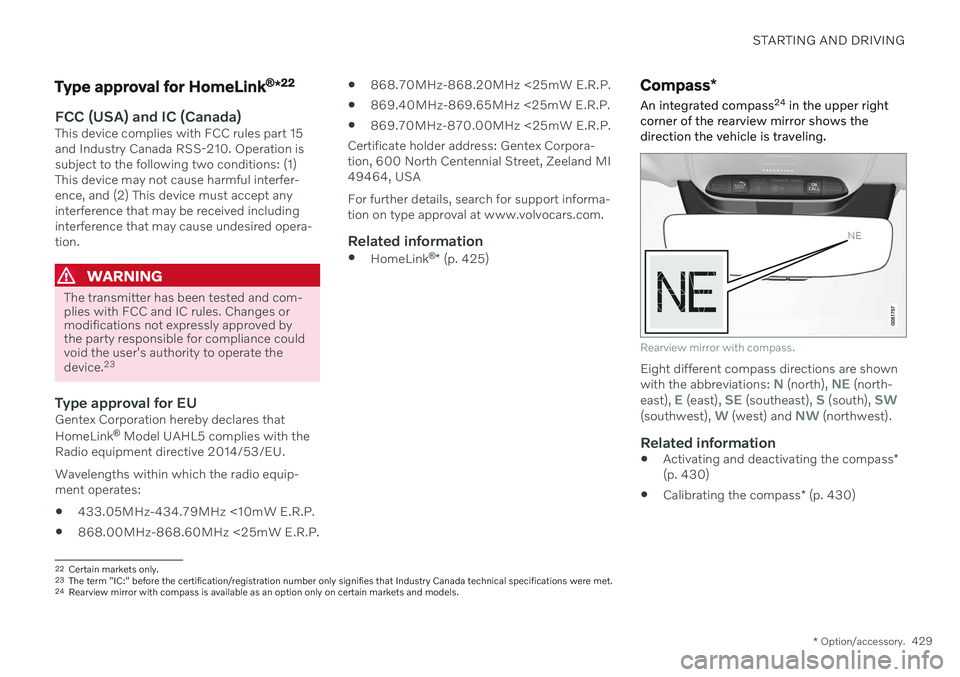
corner of the rearview mirror shows the direction the vehicle is traveling.
Rearview mirror with compass.
Eight different compass directions are shown with the abbreviations: N (north), NE (north-
east), E (east), SE (southeast), S (south), SW(southwest), W (west) and NW (northwest).
Related information
Activating and deactivating the compass
*
(p. 430)
Calibrating the compass
* (p. 430)
22
Certain markets only.
23 The term "IC:" before the certification/registration number only signifies that Industry Canada technical specifications were met.
24 Rearview mirror with compass is available as an option only on certain markets and models.
Page 432 of 643

STARTING AND DRIVING
* Option/accessory.
430
Activating and deactivating the compass *
An integrated compass 25
in the upper right
corner of the rearview mirror shows the direction the vehicle is traveling.
The compass is automatically activated when the vehicle is started. To deactivate/activate the compass manually:
–Use a paper clip or similar object to press the button on the bottom of the mirror.
> If the compass is deactivated when the vehicle is switched off, it will not be activated the next time the vehicle isstarted. The compass will then need tobe activated manually.
Related information
Compass
* (p. 429)
Calibrating the compass
* (p. 430)
Calibrating the compass *
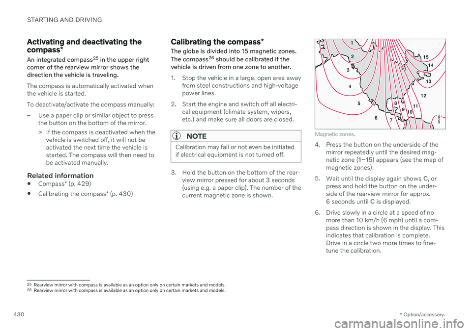
The globe is divided into 15 magnetic zones. The compass 26
should be calibrated if the
vehicle is driven from one zone to another.
1. Stop the vehicle in a large, open area away from steel constructions and high-voltage power lines.
2. Start the engine and switch off all electri- cal equipment (climate system, wipers,etc.) and make sure all doors are closed.
NOTE
Calibration may fail or not even be initiated if electrical equipment is not turned off.
3. Hold the button on the bottom of the rear-view mirror pressed for about 3 seconds (using e.g. a paper clip). The number of thecurrent magnetic zone is shown.
15
14
13
12
11
9
8
7
6
5
4
3
2
1
10
Magnetic zones.
4. Press the button on the underside of themirror repeatedly until the desired mag- netic zone (
1–15) appears (see the map of
magnetic zones).
5. Wait until the display again shows
C, or
press and hold the button on the under- side of the rearview mirror for approx.
6 seconds until
C is displayed.
6. Drive slowly in a circle at a speed of no more than 10 km/h (6 mph) until a com- pass direction is shown in the display. Thisindicates that calibration is complete.Drive in a circle two more times to fine-tune the calibration.
25Rearview mirror with compass is available as an option only on certain markets and models.
26 Rearview mirror with compass is available as an option only on certain markets and models.
Page 539 of 643

LOADING, STORAGE AND PASSENGER COMPARTMENT
* Option/accessory.537
Sun visors
In the ceiling in front of the driver's and front passenger's seats, there are sun visors thatcan be lowered and angled to the side asnecessary.
The illustration is generic – the design may vary.
The mirror lighting * comes on automatically
when the visor is lifted up. The mirror frame has a holder for e.g. cards or tickets.
Related information
Passenger compartment interior (p. 532)
Folding down the armrest in the rear seat
*
The rear seat armrest * can be folded down for
increased comfort.
The armrest is locked in the raised position and needs to be unlocked before it is foldeddown. The handle for unlocking the armrest islocated directly underneath the head restraint.
1. Grasp the handle and rotate it toward you to unlock the armrest.
2. When the handle is rotated to its maxi-mum position, the armrest is unlocked and can be folded down.
CAUTION
Before moving down the armrest, make sure to unlock it by rotating the handle.Do not pull the handle if the armrest islocked.
Make sure the armrest is securelylocked into position after it is folded up.
Page 585 of 643

MAINTENANCE AND SERVICE
}}
* Option/accessory.583
Function Ampere Type
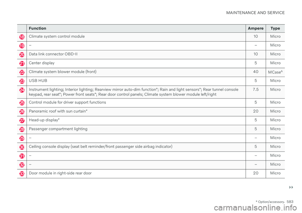
Climate system control module 10 Micro
– – Micro
Data link connector OBD-II10 Micro
Center display 5 Micro
Climate system blower module (front)40
MCaseA
USB HUB
5 Micro
Instrument lighting; Interior lighting; Rearview mirror auto-dim function*; Rain and light sensors *; Rear tunnel console
keypad, rear seat *; Power front seats *; Rear door control panels; Climate system blower module left/right 7.5 Micro
Control module for driver support functions
5 Micro
Panoramic roof with sun curtain* 20 Micro
Head-up display
* 5 Micro
Passenger compartment lighting
5 Micro
–– Micro
Ceiling console display (seat belt reminder/front passenger side airbag indicator) 5 Micro
–– Micro
–– Micro
Door module in right-side rear door20 Micro