Socket VOLVO XC90 T8 2016 Owner´s Manual
[x] Cancel search | Manufacturer: VOLVO, Model Year: 2016, Model line: XC90 T8, Model: VOLVO XC90 T8 2016Pages: 546, PDF Size: 10.26 MB
Page 213 of 546
LOADING AND STORAGE
211
Related information
•Passenger compartment storage spaces (p. 208)
• Electrical sockets (p. 212)
• Alarm (p. 226)
• Rear climate system controls on the tunnelconsole (p. 190)
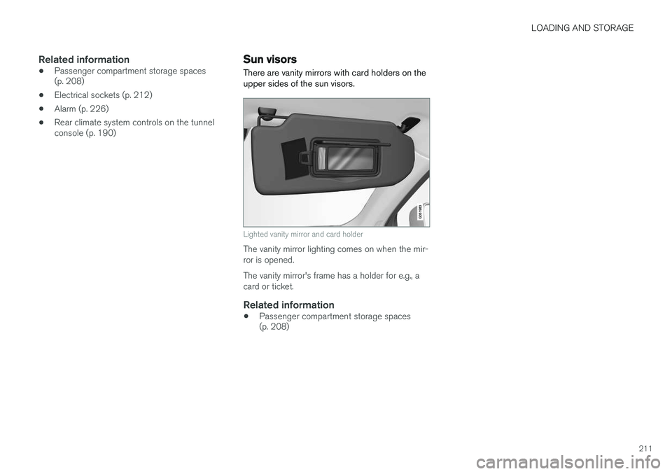
Sun visors There are vanity mirrors with card holders on the upper sides of the sun visors.
Lighted vanity mirror and card holder
The vanity mirror lighting comes on when the mir- ror is opened. The vanity mirror's frame has a holder for e.g., a card or ticket.
Related information
• Passenger compartment storage spaces (p. 208)
Page 214 of 546
LOADING AND STORAGE
* Option/accessory, for more information, see Introduction.
212
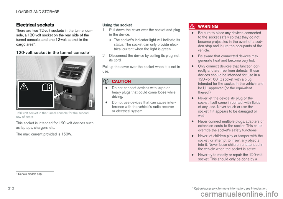
Electrical sockets There are two 12-volt sockets in the tunnel con- sole, a 120-volt socket on the rear side of thetunnel console, and one 12-volt socket in the cargo area *.
120-volt socket in the tunnel console 1
120-volt socket in the tunnel console for the second row of seats
This socket is intended for 120-volt devices such as laptops, chargers, etc. The max. current provided is 150W.
Using the socket
1. Pull down the cover over the socket and plug
in the device.
> The socket's indicator light will indicate itsstatus. The socket can only provide elec- trical current when the light is green.
2. Disconnect the device by pulling its plug, not its cord.
Pull up the cover over the socket when it is not inuse.
CAUTION
• Do not connect devices with large or heavy plugs that could come loose whiledriving.
• Do not use devices that can cause inter-ference with the vehicle's radio receiveror electrical system.
WARNING
• Be sure to place any devices connected to the socket safely so that they do notbecome projectiles in the event of a sud-den stop and injure the occupants of thevehicle.
• Be aware that connected devices maygenerate heat and become very hot.
• Only connect devices that function cor-rectly and are free from defects. Thesedevices should be intended for use in a120-volt, 60Hz socket with a plugintended for the socket in the vehicle andbe UL-approved (or the equivalentthereof).
• Never let the device, its plug or thesocket itself come in contact with fluidsof any kind. Never touch or use thesocket if it appears to be damaged orwet.
• Never connect multiple plugs, adapters orextension cords to the socket. This couldoverride the socket's safety functions.
• Never let children play or tamper with thesocket, or attempt to insert any objectsinto it. Never leave children unattended inthe vehicle when the socket is active.
• Never try to modify or repair the 120-voltsocket. This should only be done by a
1
Certain models only.
Page 215 of 546
LOADING AND STORAGE
}}
213
trained and qualified Volvo service techni- cian.
Failure to follow the points above could result in electrical shock and/or serious injury.Status indication
An LED (Light Emitting Diode) on the socket indicates its status:
Status indicator lightSocket statusAction
Steady green lightThe socket is providing current to a connected device.None.
Flashing orange lightThe socket's voltage converter is too hot (the connected device draws too much current, etc. or the temperature in the passenger compartment is very high).Unplug the device, let the converter cool down and plug in the device again.
The connected device draws too much current (constantly or currently) or is not functioning properly.None. The device should not be plugged into the socket.
Indicator light offThe socket has not detected a plugged in device.Be sure the device is correctly plugged into the socket.
The socket is not active.Put the vehicle's ignition in at least mode I.
The socket has been active but has been deactivated.Start the engine and/or charge the start battery.
If a problem persists, have the socket checked by a trained and qualified Volvo service technician.
Page 216 of 546
||
LOADING AND STORAGE
214
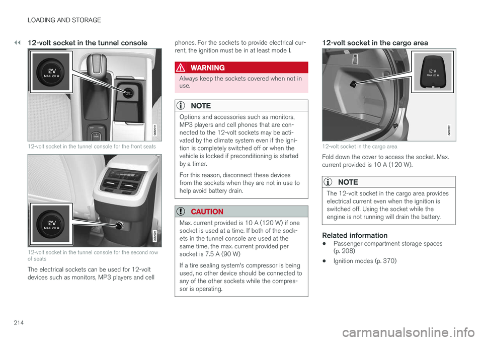
12-volt socket in the tunnel console
12-volt socket in the tunnel console for the front seats
12-volt socket in the tunnel console for the second row of seats
The electrical sockets can be used for 12-volt devices such as monitors, MP3 players and cellphones. For the sockets to provide electrical cur- rent, the ignition must be in at least mode
I.
WARNING
Always keep the sockets covered when not in use.
NOTE
Options and accessories such as monitors, MP3 players and cell phones that are con-nected to the 12-volt sockets may be acti-vated by the climate system even if the igni-tion is completely switched off or when thevehicle is locked if preconditioning is startedby a timer. For this reason, disconnect these devices from the sockets when they are not in use tohelp avoid battery drain.
CAUTION
Max. current provided is 10 A (120 W) if one socket is used at a time. If both of the sock-ets in the tunnel console are used at thesame time, the max. current provided persocket is 7.5 A (90 W) If a tire sealing system's compressor is being used, no other device should be connected toany of the other sockets while the compres-sor is operating.
12-volt socket in the cargo area
12-volt socket in the cargo area
Fold down the cover to access the socket. Max. current provided is 10 A (120 W).
NOTE
The 12-volt socket in the cargo area provides electrical current even when the ignition isswitched off. Using the socket while theengine is not running will drain the battery.
Related information
• Passenger compartment storage spaces (p. 208)
• Ignition modes (p. 370)
Page 308 of 546
||
DRIVER SUPPORT
* Option/accessory, for more information, see Introduction.
306
Speed camera alert
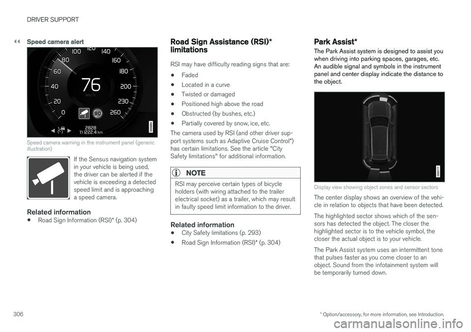
Speed camera warning in the instrument panel (generic illustration)
If the Sensus navigation system in your vehicle is being used,the driver can be alerted if thevehicle is exceeding a detectedspeed limit and is approachinga speed camera.
Related information
• Road Sign Information (RSI)
* (p. 304)
Road Sign Assistance (RSI) *
limitations
RSI may have difficulty reading signs that are:
• Faded
• Located in a curve
• Twisted or damaged
• Positioned high above the road
• Obstructed (by bushes, etc.)
• Partially covered by snow, ice, etc.
The camera used by RSI (and other driver sup- port systems such as Adaptive Cruise Control *)
has certain limitations. See the article "City Safety limitations" for additional information.
NOTE
RSI may perceive certain types of bicycle holders (with wiring attached to the trailerelectrical socket) as a trailer, which may resultin faulty speed limit information to the driver.
Related information
• City Safety limitations (p. 293)
• Road Sign Information (RSI)
* (p. 304)
Park Assist *
The Park Assist system is designed to assist you
when driving into parking spaces, garages, etc. An audible signal and symbols in the instrumentpanel and center display indicate the distance tothe object.
Display view showing object zones and sensor sectors
The center display shows an overview of the vehi- cle in relation to objects that have been detected. The highlighted sector shows which of the sen- sors has detected the object. The closer thehighlighted sector is to the vehicle symbol, thecloser the actual object is to your vehicle. The Park Assist system uses an intermittent tone that pulses faster as you come closer to anobject. Sound from the infotainment system willbe temporarily turned down.
Page 373 of 546
STARTING AND DRIVING
* Option/accessory, for more information, see Introduction.371
ModeFunctions available
0•The odometer, clock and tem- perature gauge are illuminated
• Power seats
* can be adjusted
• The power windows can be oper-ated
• The 12-volt socket in the cargocompartment can be used
• The center display is activatedand can be used
• The infotainment system can beused for a limited time
In this mode, certain functions can only be used for a limited time to helpminimize battery drain
I• The laminated panoramic roof
*,
power seats */windows,12-volt
sockets in the passenger com- partment, Bluetooth, navigation system *, climate system blower,
windshield wipers can be oper- ated
• The infotainment system will start(if it was started when the ignitionwas switched off)
Using electrical current will drain the start battery in this mode.
ModeFunctions available
II• The headlights illuminate
• Warning/indicator lights illumi- nate for 5 seconds
• A number of other functions willalso be activated. However, the heated seats
* and heated rear
window functions can only be activated when the engine is run-ning.
This mode should only be used for very short periods to help avoiddraining the battery.
Selecting an ignition mode
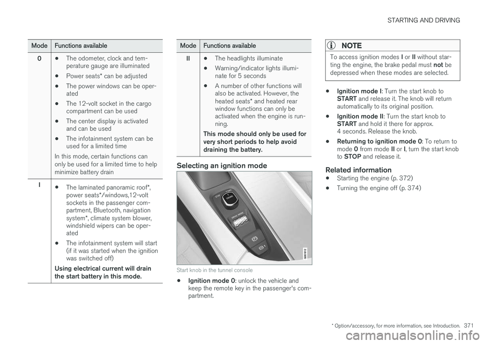
Start knob in the tunnel console
• Ignition mode 0
: unlock the vehicle and
keep the remote key in the passenger's com- partment.
NOTE
To access ignition modes I or II without star-
ting the engine, the brake pedal must not be
depressed when these modes are selected.
• Ignition mode I
: Turn the start knob to
START and release it. The knob will return
automatically to its original position.
• Ignition mode II
: Turn the start knob to
START and hold it there for approx.
4 seconds. Release the knob.
• Returning to ignition mode 0
: To return to
mode 0 from mode II or I, turn the start knob
to STOP and release it.
Related information
•Starting the engine (p. 372)
• Turning the engine off (p. 374)
Page 378 of 546
||
STARTING AND DRIVING
376
WARNING
•The charging cable must be grounded when in use. It is equipped with a cordwith a grounding conductor and agrounding plug. The plug must beinserted into an appropriate outlet that isproperly installed and grounded inaccordance with all local codes and ordi-nances and is not damaged in any way
• Children should be supervised when inthe vicinity of the charging cable when itis plugged in
• High voltage is present in your electricmeter housing and power distributionservice panel. Contact with high voltagecan cause death or serious personalinjury
• Do not use the charging cable if it isdamaged in any way
• Always position the charging cable sothat it will not be driven over, stepped on,tripped over or otherwise damaged, orcause personal injury
• Disconnect the charger from the wall out-let before cleaning it
• Never connect the charging cable to anextension cord or a multiple plug socket
•If the hybrid battery needs to be replaced, this may only be done by Volvo retailer orauthorized Volvo workshop
Also, refer to the manufacturer's instructions for using the charging cable and its compo-nents.
CAUTION
• Never unplug the charging cable from a 120-/240-volt socket while the hybridbattery is being recharged. This couldresult in damage to the socket. Alwaysstop the charging process before unplug-ging the charging cable
• To clean the charging cable, wipe it witha clean cloth dampened with water or amild detergent solution suitable for useon automobile paint. Do not use chemi-cals or solvents. Do not submerge thecharging cable
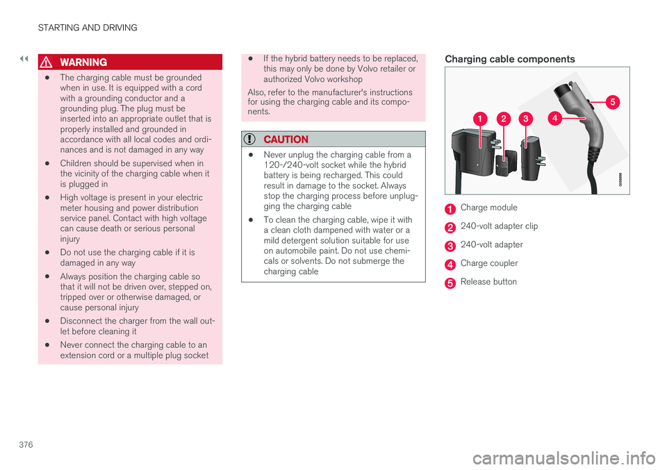
Charging cable components
Charge module
240-volt adapter clip
240-volt adapter
Charge coupler
Release button
Page 379 of 546
STARTING AND DRIVING
377
Hybrid charging cable circuit breakerThe charging cable has a circuit breaker that helps protect against current overloads andelectrical shocks.
If the charging cable's residual current breaker is triggered, the blue indicator light in the chargecoupler will not illuminate when the cable is plug-ged into a 120-/240-volt socket or the red indi-cator light will glow steadily. Have the socketchecked by a licensed electrician or try usinganother 120-/240-volt wall socket.
WARNING
• Charging the hybrid battery may only be done from approved, grounded 120-/240-volt sockets. If the electrical circuitor electrical socket's capacity is notknown, let a licensed electrician inspectthe electrical circuit's capacity. Using acharge level that exceeds the electricalcircuit's or electrical outlet's capacity maystart a fire or damage the electrical cir-cuit.
• The charging cable's residual currentbreaker helps protect the vehicle's charg-ing system but cannot ensure that an cur-rent overload will never occur.
• Never use visibly worn or damaged elec-trical sockets. Doing so could lead to firesor serious injury.
• Never connect the charging cable to anextension cord.
• Maintenance or replacement of the hybridbattery may only be performed by atrained and qualified Volvo service techni-cian.
Page 382 of 546
STARTING AND DRIVING
380
Preparations for charging the hybrid batterySeveral preparatory steps should be taken before starting to charge the hybrid battery.WARNING
• The charging cable must be grounded when in use. It is equipped with a cordwith a grounding conductor and agrounding plug. The plug must beinserted into an appropriate outlet that isproperly installed and grounded inaccordance with all local codes and ordi-nances and is not damaged in any way
• Children should be supervised when inthe vicinity of the charging cable when itis plugged in
• High voltage is present in your electricmeter housing and power distributionservice panel. Contact with high voltagecan cause death or serious personalinjury
• Do not use the charging cable if it isdamaged in any way
• Always position the charging cable sothat it will not be driven over, stepped on,tripped over or otherwise damaged, orcause personal injury
• Disconnect the charger from the wall out-let before cleaning it
• Never connect the charging cable to anextension cord or a multiple plug socket
• If the hybrid battery needs to be replaced, this may only be done by Volvo retailer orauthorized Volvo workshop
Also, refer to the manufacturer's instructions for using the charging cable and its compo-nents.
Prior to chargingThe charging cable and any of its components should not be wet or submerged in any liquid. The charge module or its plug should not be exposed to direct sunlight. This could cause theunit's overheating protector to reduce or stop thehybrid battery charging process. Be sure the 120-/240-volt socket used has ade- quate current for charging electrically poweredvehicles. Have the socket checked by an licensedelectrician if you are uncertain.
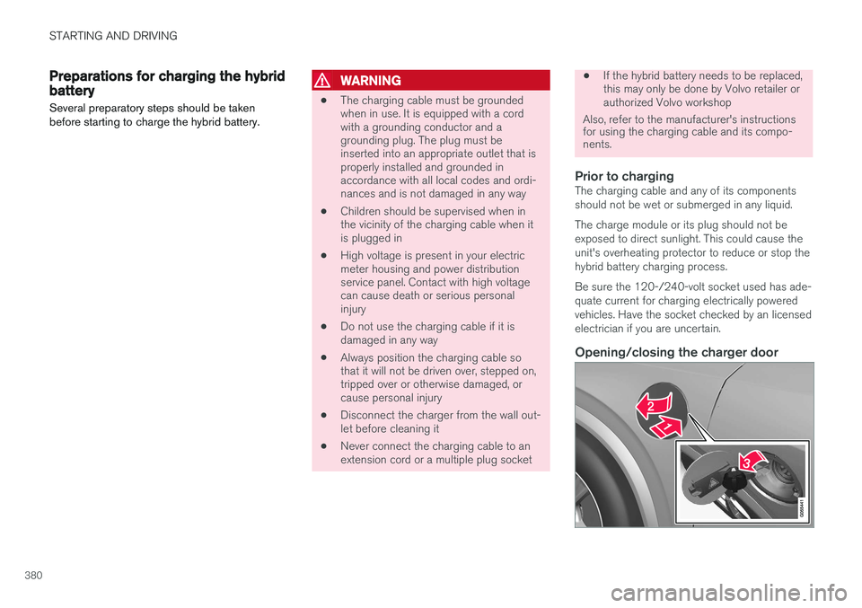
Opening/closing the charger door
Page 383 of 546
STARTING AND DRIVING
}}
381
Press in the rear section of the door and release it.
Open the door.
Pull off the charging socket's protective cover and place it in the holder on the insideof the door. Be sure that the protective cov-er's rubber plug faces down to help keep thecover from falling out of the holder.
Put the cover back in position and close the doorin reverse order.
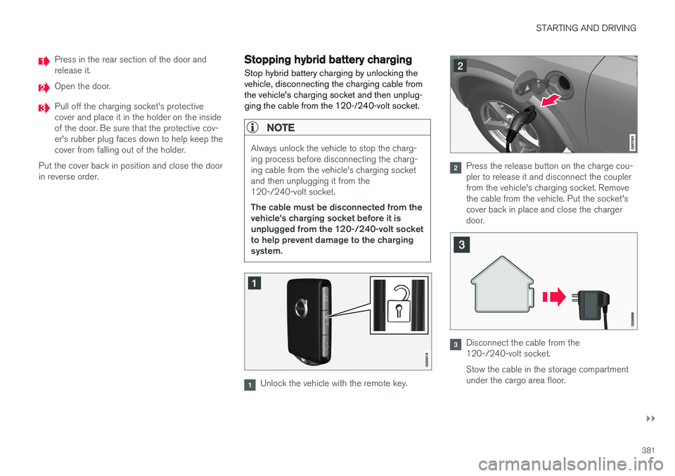
Stopping hybrid battery charging
Stop hybrid battery charging by unlocking the vehicle, disconnecting the charging cable fromthe vehicle's charging socket and then unplug-ging the cable from the 120-/240-volt socket.
NOTE
Always unlock the vehicle to stop the charg- ing process before disconnecting the charg-ing cable from the vehicle's charging socketand then unplugging it from the120-/240-volt socket. The cable must be disconnected from the vehicle's charging socket before it isunplugged from the 120-/240-volt socketto help prevent damage to the chargingsystem.
Unlock the vehicle with the remote key.
Press the release button on the charge cou- pler to release it and disconnect the couplerfrom the vehicle's charging socket. Removethe cable from the vehicle. Put the socket'scover back in place and close the chargerdoor.
Disconnect the cable from the 120-/240-volt socket. Stow the cable in the storage compartment under the cargo area floor.