mode VOLVO XC90 T8 2017 Owner´s Manual
[x] Cancel search | Manufacturer: VOLVO, Model Year: 2017, Model line: XC90 T8, Model: VOLVO XC90 T8 2017Pages: 580, PDF Size: 10.37 MB
Page 488 of 580
||
WHEELS AND TIRES
486the inflation pressure recommended by the vehi- cle manufacturer on the vehicle placard or tireinflation pressure label. (If your vehicle has tiresof a different size than the size indicated on thevehicle placard or tire inflation pressure label, youshould determine the proper tire inflation pres-sure for those tires.) As an added safety feature, your vehicle has been equipped with a tire pressure monitoringsystem (TPMS) that illuminates a low tire pres-sure telltale when one or more of your tires issignificantly under-inflated. Accordingly, when thelow tire pressure telltale illuminates, you shouldstop and check your tires as soon as possible,and inflate them to the proper pressure. Driving on a significantly under-inflated tire cau- ses the tire to overheat and can lead to tire fail-ure. Under-inflation also reduces fuel efficiencyand tire tread life, and may affect the vehicle'shandling and stopping ability. Please note thatthe TPMS is not a substitute for proper tire main-tenance, and it is the driver's responsibility tomaintain correct tire pressure, even if under-infla-tion has not reached the level to trigger illumina-tion of the TPMS low tire pressure telltale. Your vehicle has also been equipped with a TPMS malfunction indicator to indicate when thesystem is not operating properly. The TPMS mal-function indicator is combined with the low tirepressure telltale.
When the system detects a malfunction, the tell-tale will flash for approximately one minute andthen remain continuously illuminated. Thissequence will continue upon subsequent vehiclestart-ups as long as the malfunction exists. Whenthe malfunction indicator is illuminated, the sys-tem may not be able to detect or signal low tirepressure as intended. TPMS malfunctions may occur for a variety of reasons, including the installation of replacementor alternate tires or wheels on the vehicle thatprevent the TPMS from functioning properly.Always check the TPMS malfunction telltale afterreplacing one or more tires or wheels on yourvehicle to ensure that the replacement or alter-nate tires and wheels allow the TPMS to con-tinue to function properly.
Messages in the instrument panel
When the TPMS symbol illuminates, the following text messages may also be displayed:
•
Tire pressure low
•Tire pressure system Temporarily
unavailable
•Tire pressure system Service required
If TPMS cannot determine which tire(s) have low inflation pressure:
• All four tires will be shown as affected in thecenter display After changing wheels, always calibrate the sys-tem to avoid false warnings. TPMS does not replace the need for regular tire inspection and maintenance.
NOTE
If you change to tires with a different dimen- sion than the factory-installed ones, theTPMS system must be calibrated for thesetires. TPMS cannot be turned off.
WARNING
Incorrect inflation pressure could lead to tire failure, resulting in a loss of control of thevehicle.
Related information
•
Checking tire inflation pressure (p. 487)
• Reinflating tires equipped with the Tire Pressure Monitoring System (TPMS)(p. 488)
• Ignition modes (p. 389)
Page 489 of 580
WHEELS AND TIRES
487
Checking tire inflation pressure
The Tire Pressure Monitoring System (TPMS) makes it possible to view the current inflationpressure status of all four tires.
Checking inflation pressureOpen the Car status app in
the center display's Application view. Tap
Status to see the
current inflation pressure sta- tus of all four tires.
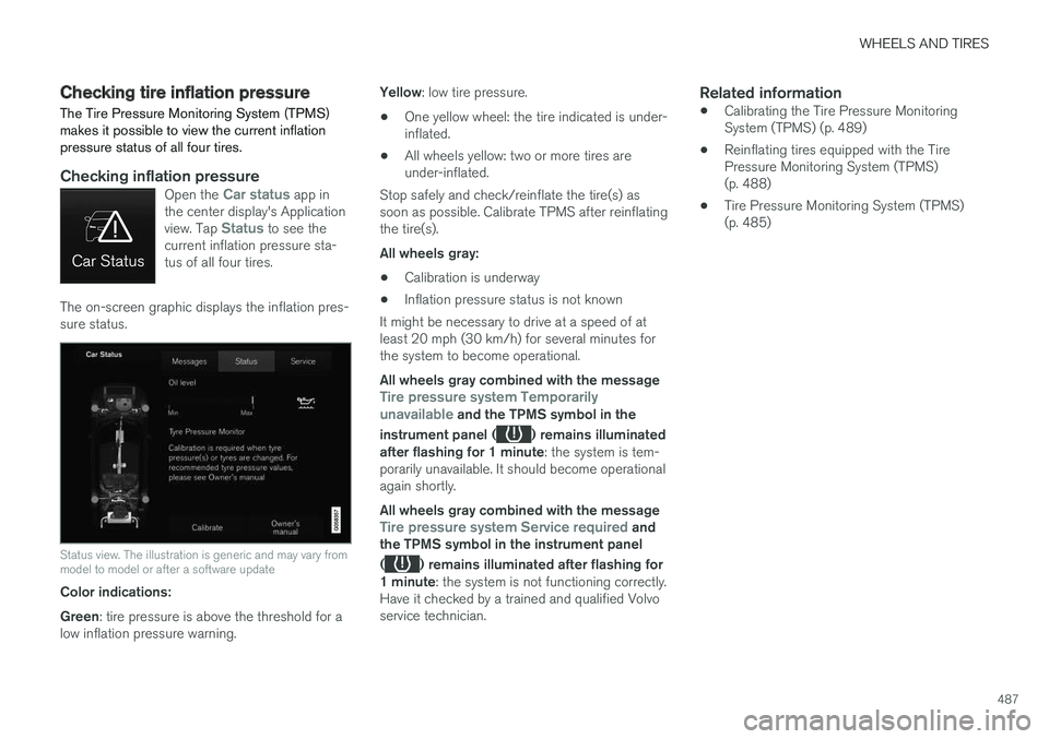
The on-screen graphic displays the inflation pres- sure status.
Status view. The illustration is generic and may vary from model to model or after a software update
Color indications: Green : tire pressure is above the threshold for a
low inflation pressure warning. Yellow
: low tire pressure.
• One yellow wheel: the tire indicated is under- inflated.
• All wheels yellow: two or more tires areunder-inflated.
Stop safely and check/reinflate the tire(s) assoon as possible. Calibrate TPMS after reinflatingthe tire(s). All wheels gray:
• Calibration is underway
• Inflation pressure status is not known
It might be necessary to drive at a speed of at least 20 mph (30 km/h) for several minutes forthe system to become operational. All wheels gray combined with the message
Tire pressure system Temporarily
unavailable and the TPMS symbol in the
instrument panel (
) remains illuminated
after flashing for 1 minute : the system is tem-
porarily unavailable. It should become operational again shortly. All wheels gray combined with the message
Tire pressure system Service required and
the TPMS symbol in the instrument panel (
) remains illuminated after flashing for
1 minute : the system is not functioning correctly.
Have it checked by a trained and qualified Volvo service technician.
Related information
• Calibrating the Tire Pressure MonitoringSystem (TPMS) (p. 489)
• Reinflating tires equipped with the TirePressure Monitoring System (TPMS)(p. 488)
• Tire Pressure Monitoring System (TPMS)(p. 485)
Page 492 of 580
WHEELS AND TIRES
* Option/accessory.
490
Tire sealing system 5
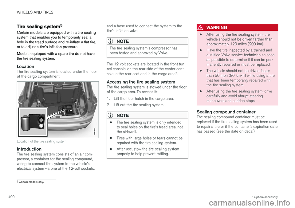
Certain models are equipped with a tire sealing system that enables you to temporarily seal ahole in the tread surface and re-inflate a flat tire,or to adjust a tire
Page 510 of 580
||
MAINTENANCE AND SERVICING
508
WARNING
In certain models, the battery is held in place by a strap. Ensure that this strap is alwayssecurely fastened and pulled taut.
• When replacing the start battery an Absorbed Glass Mat (AGM) must be used.
• When replacing the start battery, a new bat-tery with the same specifications and dimen-sions must be used. The battery should onlybe replaced by a trained and qualified Volvoservice technician.
Related information
•
Jump starting (p. 382)
• Hybrid battery (p. 508)
• Charging the hybrid battery (p. 403)
• Battery symbols (p. 509)
Hybrid battery
The vehicle's electric motor is powered by a rechargeable, maintenance-free, lithium-ionhybrid battery.
The vehicle cannot be started if the hybrid battery is completely discharged.
WARNING
The vehicle's hybrid battery may only be serv- iced or replaced by a trained and qualifiedVolvo service technician.
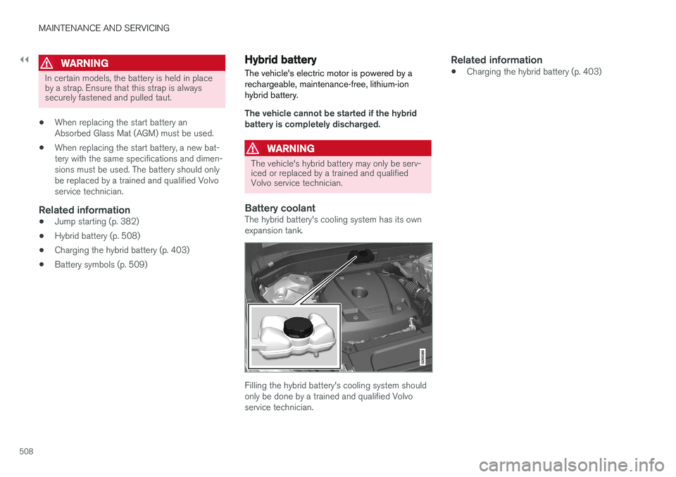
Battery coolantThe hybrid battery's cooling system has its own expansion tank.
Filling the hybrid battery's cooling system should only be done by a trained and qualified Volvoservice technician.
Related information
• Charging the hybrid battery (p. 403)
Page 515 of 580
![VOLVO XC90 T8 2017 Owner´s Manual MAINTENANCE AND SERVICING
}}
* Option/accessory.513
replaced by a trained and qualified Volvo service technician.
Function
[A]
Converter for controlling feed to the rear axle electric motor 5
– –](/img/45/36380/w960_36380-514.png "VOLVO XC90 T8 2017 Owner´s Manual MAINTENANCE AND SERVICING
}}
* Option/accessory.513
replaced by a trained and qualified Volvo service technician.
Function
[A]
Converter for controlling feed to the rear axle electric motor 5
– –")
MAINTENANCE AND SERVICING
}}
* Option/accessory.513
replaced by a trained and qualified Volvo service technician.
Function
[A]
Converter for controlling feed to the rear axle electric motor 5
– –
– –
Control module for actuator for engaging/changing gears5
High Voltage Coolant Heater control module5
Control module for: A/C, charge module, heat exchanger cut-offvalve, cut-off valve for coolantthrough the climate system5
Hybrid battery control module; high-voltage converter for com-bined high-voltage generator/starter motor with 500 V–12 Vvoltage converter5
– –
Converter for controlling feed to the rear axle electric motor
10
Function
[A]
Hybrid battery control module for high-voltage converter forcombined high-voltage genera-tor/starter motor with 500 V–12V voltage converter 10
Charging module 5
Cut-off valve for hybrid battery coolant; coolant pump 1 forhybrid battery
10
Coolant pump for electric drive system
10
Hybrid component cooling fan 25
– –
– –
– –
– –
– –
– –
– –
– –
Function
[A]
Front USB socket* 5
12-volt socket in the front tun- nel console 15
12-volt socket on the rear side of the tunnel console
A
12-volt socket in the tunnel con-sole between the rear seats B15
12-volt socket in the cargo com- partment USB sockets for iPad holders
B15
– –
Driver's side headlight, certain LED models
15
Passenger's side headlight, cer- tain LED models15
– –
Heated windshield
* driver side Shunt
Heated windshield
* driver side 40
Headlight washers
*25
Windshield washer 25
Page 516 of 580
![VOLVO XC90 T8 2017 Owner´s Manual ||
MAINTENANCE AND SERVICING
* Option/accessory.
514
Function [A]
– –
Horn 20
Alarm siren* 5
Brake system control module (valves, parking brake) 40
Windshield wipers 30
Tailgate window washer 25
H](/img/45/36380/w960_36380-515.png "VOLVO XC90 T8 2017 Owner´s Manual ||
MAINTENANCE AND SERVICING
* Option/accessory.
514
Function [A]
– –
Horn 20
Alarm siren* 5
Brake system control module (valves, parking brake) 40
Windshield wipers 30
Tailgate window washer 25
H")
||
MAINTENANCE AND SERVICING
* Option/accessory.
514
Function [A]
– –
Horn 20
Alarm siren* 5
Brake system control module (valves, parking brake) 40
Windshield wipers 30
Tailgate window washer 25
Heated windshield
*, passenger
side 40
– –
Brake system control module (ABS pump)
40
– –
Heated windshield
*, passenger
side Shunt
Feed when ignition is switched on to: engine control module,transmission components, elec-trical power steering, centralelectrical module 5
Exterior vehicle sound (certain markets)
5
Function
[A]
Passenger side headlight 7,5
– –
– –
– –
Air bags; Occupant Weight Sen- sor (OWS) 5
Driver side headlight Driver's side headlight, certain LED models7.5
15
Accelerator pedal sensor 5
Transmission control module; Gear selector control module 15
Engine control module 5
– –
– –
– –
– –
Engine control module; Actuator; Turbo-charger valve20
Function
[A]
Solenoids; Valves; Engine cool- ing system thermostat 10
Vacuum regulators; Valve 7.5
Spoiler shutter control module; Radiator shutter control module;Fuel leakage detection 5
– –
Heated oxygen sensors (front and rear)
15
Oil pump solenoid; A/C mag- netic coupling; heated oxygensensor (center)15
– –
Engine control module 20
Ignition coils; Spark plugs 15
– –
– –
Transmission oil pump control module
30
Vacuum pump control module 40
Transmission actuator 25
Page 526 of 580
MAINTENANCE AND SERVICING
524
Replacing bulbs
The halogen headlight bulbs 3
can be replaced
by the owner.
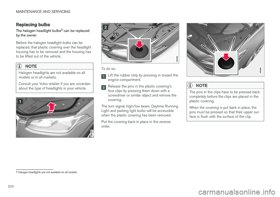
Before the halogen headlight bulbs can be replaced, that plastic covering over the headlighthousing has to be removed and the housing hasto be lifted out of the vehicle.
NOTE
Halogen headlights are not available on all models or in all markets. Consult your Volvo retailer if you are uncertain about the type of headlights in your vehicle.To do so:
Lift the rubber strip by pressing in toward the engine compartment.
Release the pins in the plastic covering's four clips by pressing them down with ascrewdriver or similar object and remove thecovering.
The turn signal, high/low beam, Daytime RunningLight and parking light bulbs will be accessiblewhen the plastic covering has been removed. Put the covering back in place in the reverse order.NOTE
The pins in the clips have to be pressed back completely before the clips are placed in theplastic covering. When the covering is put back in place, the pins must be pressed so that their upper sur-face is flush with the surface of the clip.
3 Halogen headlights are not available on all models.
Page 527 of 580
MAINTENANCE AND SERVICING
}}
525
NOTE
•For information regarding any bulbs not mentioned in this section, please contactyour Volvo retailer or a trained andauthorized Volvo service technician.
• Always switch off the ignition before star-ting to replace a bulb.
• If an error message remains in the dis-play after a faulty bulb has been replaced,contact an authorized Volvo workshop.
• Condensation may form temporarily onthe inside of the lenses of exterior lightssuch as headlights, fog lights, or taillights.This is normal and the lights aredesigned to withstand moisture. Normally,condensation will dissipate after thelights have been on for a short time.
• The optional Active Bending Light bulbscontain trace amounts of mercury. Thesebulbs should always be disposed of by atrained and qualified Volvo service techni-cian.
CAUTION
Never touch the glass of bulbs with your fin- gers. Grease and oils from your fingers vapor-ize in the heat and will leave a deposit on thereflector, which will damage it.
WARNING
• The ignition should be switched off com- pletely (be in ignition mode
0) when
replacing bulbs.
• If the engine has been running just prior to replacing bulbs in the headlight hous-ing, please keep in mind that componentsin the engine compartment will be hot.
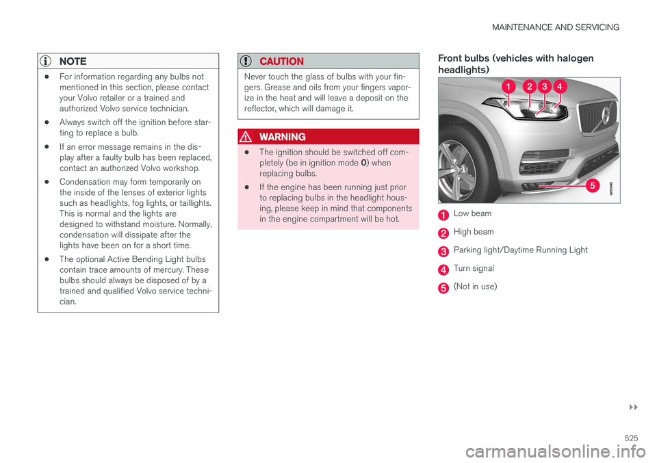
Front bulbs (vehicles with halogen headlights)
Low beam
High beam
Parking light/Daytime Running Light
Turn signal
(Not in use)
Page 528 of 580
||
MAINTENANCE AND SERVICING
526
Taillight bulbs
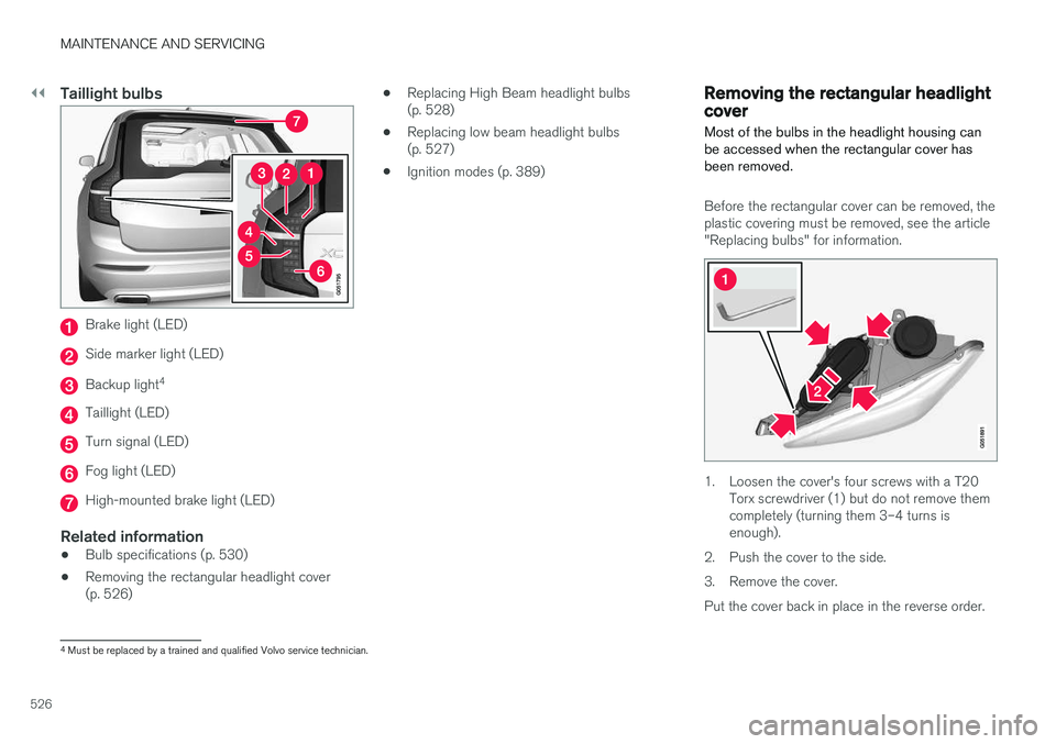
Brake light (LED)
Side marker light (LED)
Backup light4
Taillight (LED)
Turn signal (LED)
Fog light (LED)
High-mounted brake light (LED)
Related information
•
Bulb specifications (p. 530)
• Removing the rectangular headlight cover (p. 526) •
Replacing High Beam headlight bulbs(p. 528)
• Replacing low beam headlight bulbs(p. 527)
• Ignition modes (p. 389)
Removing the rectangular headlight cover
Most of the bulbs in the headlight housing can be accessed when the rectangular cover hasbeen removed.
Before the rectangular cover can be removed, the plastic covering must be removed, see the article"Replacing bulbs" for information.
1. Loosen the cover's four screws with a T20 Torx screwdriver (1) but do not remove them completely (turning them 3–4 turns isenough).
2. Push the cover to the side.
3. Remove the cover.Put the cover back in place in the reverse order.
4 Must be replaced by a trained and qualified Volvo service technician.
Page 529 of 580
MAINTENANCE AND SERVICING
527
Related information
•Replacing bulbs (p. 524)
Replacing low beam headlight bulbs
On models with halogen headlights, the low beam headlight bulb can be replaced by theowner.
Before the bulb can be replaced, the plastic cov- ering over the headlight housing has to be removed, see the article "Replacing bulbs."
CAUTION
Never touch the glass of bulbs with your fin- gers. Grease and oils from your fingers vapor-ize in the heat and will leave a deposit on thereflector, which will damage it.
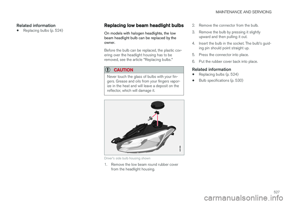
Driver's side bulb housing shown
1. Remove the low beam round rubber cover from the headlight housing. 2. Remove the connector from the bulb.
3. Remove the bulb by pressing it slightly
upward and then pulling it out.
4. Insert the bulb in the socket. The bulb's guid- ing pin should point straight up.
5. Press the connector into place.
6. Put the rubber cover back into place.
Related information
• Replacing bulbs (p. 524)
• Bulb specifications (p. 530)