ESP VOLVO XC90 TWIN ENGINE 2019 Owner's Manual
[x] Cancel search | Manufacturer: VOLVO, Model Year: 2019, Model line: XC90 TWIN ENGINE, Model: VOLVO XC90 TWIN ENGINE 2019Pages: 697, PDF Size: 10.33 MB
Page 245 of 697
KEY, LOCKS AND ALARM
}}
* Option/accessory. 243
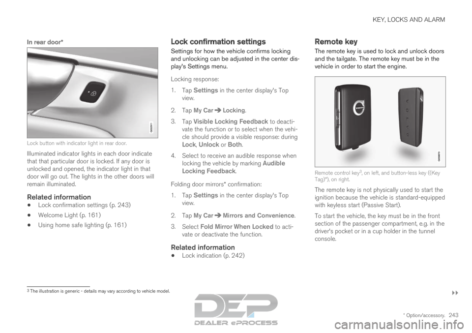
In rear door*Lock button with indicator light in rear door.
Illuminated indicator lights in each door indicate
that that particular door is locked. If any door is
unlocked and opened, the indicator light in that
door will go out. The lights in the other doors will
remain illuminated.
Related information
Lock confirmation settings (p. 243)
Welcome Light (p. 161)
Using home safe lighting (p. 161) Lock confirmation settings
Settings for how the vehicle confirms locking
and unlocking can be adjusted in the center dis-
play's Settings menu.
Locking response:
1.
Tap Settings in the center display's Top
view.
2.
Tap My Car Locking
.
3. Tap Visible Locking Feedback to deacti-
vate the function or to select when the vehi-
cle should provide a visible response: during
Lock, Unlock or Both.
4.
Select to receive an audible response when
locking the vehicle by marking Audible
Locking Feedback.
Folding door mirrors* confirmation:
1. Tap Settings in the center display's Top
view.
2.
Tap My Car Mirrors and Convenience
.
3. Select Fold Mirror When Locked to acti-
vate or deactivate the function.
Related information
Lock indication (p. 242) Remote key
The remote key is used to lock and unlock doors
and the tailgate. The remote key must be in the
vehicle in order to start the engine. Remote control key
3
, on left, and button-less key ((Key
Tag)*), on right.
The remote key is not physically used to start the
ignition because the vehicle is standard-equipped
with keyless start (Passive Start).
To start the vehicle, the key must be in the front
section of the passenger compartment, e.g. in the
driver's pocket or in a cup holder in the tunnel
console. 3
The illustration is generic - details may vary according to vehicle mode\
l.
Page 260 of 697
||KEY, LOCKS AND ALARM
* Option/accessory.
258 (1) This device may not cause harmful interfer-
ence, and
(2) this device must accept any interference
received, including interference that may cause
undesired operation.
Any changes or modification not expressly
approved by the party responsible for compliance
could void the user's authority to operate this
equipment.
Canada
Volvo Standard Key IC: 4008C-HUF8423
Volvo Tag ID IC: 4008C-HUF8432
This device complies with Industry Canada
license-exempt RSS standards. Operation is sub-
ject to the following two conditions:
(1) This device may not cause harmful interfer-
ence, and (2) this device must accept any inter-
ference received, including interference that may
cause undesired operation.
Immobilizer and Passive entry/Passive
start* systems
USA-FCC ID: LTQVO3134
This device complies with part 15 of the FCC
rules. Operation is subject to the following two
conditions:
(1) This device may not cause harmful interfer-
ence, and (2) this device must accept any interference
received, including interference that may cause
undesired operation.
Any changes or modification not expressly
approved by the party responsible for compliance
could void the user's authority to operate this
equipment.
Canada-IC:3659A-VO3134
This device complies with Industry Canada
license-exempt RSS standards. Operation is sub-
ject to the following two conditions:
(1) This device may not cause harmful interfer-
ence, and (2) this device must accept any inter-
ference received, including interference that may
cause undesired operation.
Related information
Remote key (p. 243) Keyless and touch-sensitive
surfaces*
If the vehicle is equipped with keyless locking
and unlocking, it is only necessary to have the
remote key within range, e.g. in a pocket or bag,
which makes it easier to open the vehicle if your
hands are full.
Page 282 of 697
||DRIVER SUPPORT
* Option/accessory.
280
WARNING
The Electronic Stability Control system
ESC is supplementary driver support
intended to facilitate driving and make it
safer – it cannot handle all situations in
all traffic, weather and road conditions.
ESC is not a substitute for the driver's
attention and judgment. The driver is
always responsible for ensuring the vehi-
cle is driven in a safe manner, at the
appropriate speed, with an appropriate
distance to other vehicles, and in accord-
ance with current traffic rules and regula-
tions.
Stability control 3This function helps control the driving and brak-
ing force of each individual wheel in an attempt
to stabilize the vehicle.
Spin control and active yaw controlThis function is active at low speeds and brakes
the wheels that are spinning to transfer additional
power from wheels that are not spinning.
This function also helps prevent the wheels from
spinning while the vehicle is accelerating.
Engine drag control
Engine drag control (EDC
4
) helps prevent inad-
vertent wheel lock, e.g. after downshifting or
using engine braking when driving at low speeds
on a slippery surface.
Inadvertent wheel lock while driving could impair
the driver's ability to steer the vehicle.
Trailer Stability Assist* 5
Trailer Stability Assist (TSA
6
) is designed to help
stabilize a vehicle that is towing a trailer if the
vehicle and trailer have begun to sway. For more
information, see "Trailer Stability Assist".
NOTE The TSA function is deactivated if
ESC Sport
Mode is activated.
Related information
Electronic Stability Control Sport mode
(p. 281)
Activating/deactivating Sport mode in Elec-
tronic Stability Control (p. 281)
Electronic Stability Control Sport mode limi-
tations (p. 281)
Electronic Stability Control symbols and mes-
sages (p. 282)
Trailer Stability Assist* (p. 485)
3
Also called traction control.4 Engine Drag Control5Trailer Stability Assist is included if the vehicle is equipped with a V\
olvo original towbar.6 Trailer Stability Assist
Page 285 of 697
DRIVER SUPPORT
283
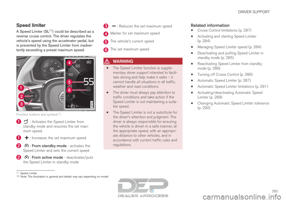
Speed limiter
A Speed Limiter (SL 11
) could be described as a
reverse cruise control. The driver regulates the
vehicle's speed using the accelerator pedal, but
is prevented by the Speed Limiter from inadver-
tently exceeding a preset maximum speed. Function buttons and symbols
12
. : Activates the Speed Limiter from
standby mode and resumes the set maxi-
mum speed. : Increases the set maximum speed
: From standby mode - activates the
Speed Limiter and sets the current speed : From active mode - deactivates/puts
the Speed Limiter in standby mode : Reduces the set maximum speed
Marker for set maximum speed
The vehicle's current speed
The set maximum speed
WARNING
The Speed Limiter function is supple-
mentary driver support intended to facili-
tate driving and help make it safer – it
cannot handle all situations in all traffic,
weather and road conditions.
The driver must always pay attention to
traffic conditions and take action if the
Speed Limiter is not maintaining a suita-
ble speed.
The Speed Limiter is not a substitute for
the driver's attention and judgment. The
driver is always responsible for ensuring
the vehicle is driven in a safe manner, at
the appropriate speed, with an appropri-
ate distance to other vehicles, and in
accordance with current traffic rules and
regulations.
Related information
Cruise Control limitations (p. 287)
Activating and starting Speed Limiter
(p. 284)
Managing Speed Limiter speed (p. 284)
Deactivating and putting Speed Limiter in
standby mode (p. 285)
Reactivating Speed Limiter from standby
mode (p. 286)
Turning off Cruise Control (p. 286)
Automatic Speed Limiter (p. 287)
Automatic Speed Limiter limitations (p. 291)
Activating/deactivating Automatic Speed
Limiter (p. 289)
Changing Automatic Speed Limiter tolerance
(p. 290) 11
Speed Limiter
12 Note: This illustration is general and details may vary depending on mod\
el.
Page 290 of 697
||DRIVER SUPPORT
288
WARNING
The ASL function is supplementary driver
support intended to facilitate driving and
help make it safer – it cannot handle all
situations in all traffic, weather and road
conditions.
Even if the driver can clearly see the
speed limit sign, the speed information
from the Road Sign Information (RSI)
function to ASL may be incorrect. In such
cases, the driver must intervene and
accelerate or brake to an appropriate
speed.
ASL is not a substitute for the driver's
attention and judgment. The driver is
always responsible for ensuring the vehi-
cle is driven in a safe manner, at the
appropriate speed, with an appropriate
distance to other vehicles, and in accord-
ance with current traffic rules and regula-
tions.
See also the heading "Road Sign Infor-
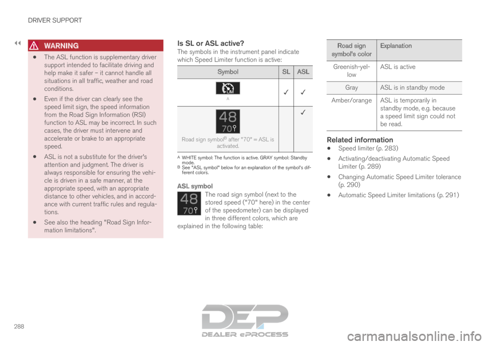
mation limitations".Is SL or ASL active?The symbols in the instrument panel indicate
which Speed Limiter function is active: Symbol
SLASL A
✓ ✓ Road sign symbol
B
after "70" = ASL is
activated. ✓ A
WHITE symbol: The function is active. GRAY symbol: Standby
mode.
B See "ASL symbol" below for an explanation of the symbol's dif-
ferent colors.
ASL symbol
The road sign symbol (next to the
stored speed ("70" here) in the center
of the speedometer) can be displayed
in three different colors, which are
explained in the following table: Road sign
symbol's color Explanation
Greenish-yel- low ASL is active
Gray
ASL is in standby mode
Amber/orange ASL is temporarily in standby mode, e.g. because
a speed limit sign could not
be read.
Related information
Speed limiter (p. 283)
Activating/deactivating Automatic Speed
Limiter (p. 289)
Changing Automatic Speed Limiter tolerance
(p. 290)
Automatic Speed Limiter limitations (p. 291)
Page 294 of 697

||DRIVER SUPPORT
292
WARNING
The cruise control function is supplemen-
tary driver support intended to facilitate
driving and help make it safer – it cannot
handle all situations in all traffic, weather
and road conditions.
The driver is advised to read all sections
in the Owner's Manual about this function
to learn of its limitations, which the driver
must be aware of before using the func-
tion (see the link list at the end of this
article).
Cruise control is not a substitute for the
driver's attention and judgment. The driver
is always responsible for ensuring the
vehicle is driven in a safe manner, at the
appropriate speed, with an appropriate
distance to other vehicles, and in accord-
ance with current traffic rules and regula-
tions.
Related information
Activating and starting Cruise Control
(p. 292)
Managing Cruise Control speed (p. 293)
Deactivating and putting Cruise Control in
standby mode (p. 294)
Reactivating Cruise Control from standby
mode (p. 295)
Switching off Cruise Control (p. 296)
Switching between Cruise Control and Adap-
tive Cruise Control (p. 313) Activating and starting Cruise
Control
The Cruise Control (CC 24
) function must be
selected and activated in order to regulate
speed. Note: This illustration is general and details may vary
depending on model.
Putting Cruise Control in standby modeTo put Cruise Control in standby mode:
–
Tap ◀ (1) or ▶ (3) and scroll to the (4) function.
>
A symbol will appear and Cruise Control
can then be activated.
Activating/starting Cruise ControlIn order to start Cruise Control from standby
mode, the vehicle's current speed must be
Page 302 of 697
||DRIVER SUPPORT
* Option/accessory.
300
WARNING
The radar sensor has a limited field of
vision. In some situations, it may detect a
vehicle later than expected or not detect
other vehicles at all.
The radar sensor cannot cover all driving
situations and traffic, weather and road
conditions.
The driver is responsible for maintaining a
safe distance and speed and must inter-
vene if the various driver support systems
do not maintain a suitable speed or suita-
ble distance to the vehicle ahead.
Maintenance of radar sensor components
may only be performed by a trained and
qualified Volvo technician.
Strong sunlight, reflections from the road
surface, strong lighting contrasts or using
sunglasses may make the warning light in
the windshield difficult to see. Poor
weather or winding roads can affect the
radar sensor's capacity to detect vehicles
ahead.
A vehicle's size (e.g., a motorcycle) can
also affect the radar sensor's capacity to
detect another vehicle. This may result in
the warning light illuminating at a shorter
distance than the one that has been set
or not illuminating at all.
High speeds may also result in the warn-
ing light illuminating at a shorter distance
than the one that has been set due to
limitations in the radar sensor's range.
NOTE The function uses the vehicle's radar unit,
which has some general limitations – see the
section "Radar unit limitations".
Related information
Distance Alert* (p. 296)
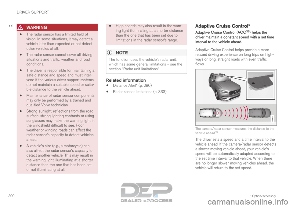
Radar sensor limitations (p. 333) Adaptive Cruise Control*
Adaptive Cruise Control (ACC 38
) helps the
driver maintain a constant speed with a set time
interval to the vehicle ahead.
Adaptive Cruise Control helps provide a more
relaxed driving experience on long trips on high-
ways or long, straight roads with even traffic
flows. The camera/radar sensor measures the distance to the
vehicle ahead
39
.
The driver sets a speed and a time interval to the
vehicle ahead. If the camera/radar sensor detects
a slower-moving vehicle ahead, your vehicle's
speed will be automatically adapted according to
the set time interval to that vehicle. When there
are no longer slower-moving vehicles ahead, the
vehicle will return to the set speed.
Page 303 of 697
DRIVER SUPPORT
}}
301
WARNING
The Adaptive Cruise Control function is
supplementary driver support intended to
facilitate driving and help make it safer –
it cannot handle all situations in all traffic,
weather and road conditions.
The driver is advised to read all sections
in the Owner's Manual about this function
to learn of its limitations, which the driver
must be aware of before using the func-
tion (see the link list at the end of this
article).
Adaptive Cruise Control is not a substi-
tute for the driver's attention and judg-
ment. The driver is always responsible for
ensuring the vehicle is driven in a safe
manner, at the appropriate speed, with an
appropriate distance to other vehicles,
and in accordance with current traffic
rules and regulations.
NOTE Depending on market, this function may be
either Standard or Optional.
Adaptive Cruise Control regulates speed by
accelerating and braking. It is normal for the brakes to emit a slight sound when they are
being used to adjust speed.
Adaptive Cruise Control always attempts to regu-
late speed smoothly. The driver must apply the
brakes in situations requiring immediate braking.
For example, when there are great differences in
speed between vehicles or if the vehicle ahead
brakes suddenly. Due to limitations in the radar
sensor, braking may occur unexpectedly or not at
all.
Adaptive Cruise Control is designed to follow a
vehicle ahead in the same lane and maintain a
time interval to that vehicle set by the driver. If the
radar sensor does not detect a vehicle ahead, it
will instead maintain the speed set by the driver.
This will also happen if the speed of the vehicle
ahead exceeds the set speed for your vehicle.
Adaptive Cruise Control can follow another
vehicle at speeds from a standstill up to
200 km/h (125 mph).
WARNING
Adaptive Cruise Control is not a collision
avoidance system. The driver is always
responsible and must intervene if the sys-
tem fails to detect a vehicle ahead.
Adaptive Cruise Control does not brake
for people or animals and does not brake
for small vehicles, such as bikes and
motorcycles. Similarly, it does not brake
for low trailers, oncoming, slow-moving or
stationary vehicles and objects.
Do not use Adaptive Cruise Control in
demanding situations, such as in city traf-
fic, at intersections, on slippery surfaces,
with a lot of water or slush on the road, in
heavy rain/snow, in poor visibility, on
winding roads, or on on/off ramps.
CAUTION Maintenance of Adaptive Cruise Control com-
ponents may only be performed by a work-
shop – an authorized Volvo workshop is rec-
ommended.
38
Adaptive Cruise Control
39 Note: This illustration is general and details may vary depending on mod\
el.
Page 309 of 697

DRIVER SUPPORT
}}
* Option/accessory. 307
NOTE
The greater the vehicles' speed, the
greater the distance between them for a
set time interval.
Only use the time intervals permitted by
local traffic regulations.
If the Adaptive Cruise Control does not
seem to respond with a speed increase
when activated, it may be because the
time interval to the vehicle ahead is
shorter than the set time interval.
WARNING
Only use a time interval suitable for the
current traffic conditions.
The driver should be aware that short
time intervals give them limited time to
react and act to any unforeseen traffic
situation.
Setting how ACC should maintain
distance* to the vehicle ahead
A number of different settings can be made for
how Adaptive Cruise Control should maintain a
time interval to the vehicle ahead. Settings are
made using the DRIVE MODE controls. Select one of the following:
Eco - ACC will focus on providing optimal
fuel economy, which will increase the time
interval to the vehicle ahead.
Comfort - ACC will focus on following the
set time interval to the vehicle ahead as
smoothly as possible.
Dynamic
- ACC will focus on following the
set time interval to the vehicle ahead more
exactly, which could mean faster acceleration
and heavier braking.
For more information, see "Drive modes".
Related information
Adaptive Cruise Control* (p. 300)
Drive modes (p. 454)
Managing Cruise Control speed (p. 293) Deactivating/reactivating Adaptive
Cruise Control
Adaptive Cruise Control (ACC
46
) can be tempo-
rarily put into standby mode and then reactiva-
ted.
Deactivating and putting Adaptive
Cruise Control in standby mode Note: This illustration is general and details may vary
depending on model.
46
Adaptive Cruise Control
Page 319 of 697
DRIVER SUPPORT
}}
317
WARNING
The Pilot Assist function is supplementary
driver support intended to facilitate driv-
ing and help make it safer – it cannot
handle all situations in all traffic, weather
and road conditions.
The driver is advised to read all sections
in the Owner's Manual about this function
to learn of its limitations, which the driver
must be aware of before using the func-
tion (see the link list at the end of this
article).
Pilot Assist should only be used if there
are clear lane lines painted on each side
of the lane. All other use will increase the
risk of contact with nearby obstacles that
cannot be detected by the functions.
Pilot Assist is not a substitute for the driv-
er's attention and judgment. The driver is
always responsible for ensuring the vehi-
cle is driven in a safe manner, at the
proper position within the lane, at the
appropriate speed, with an appropriate
distance to other vehicles, and in accord-
ance with current traffic rules and regula-
tions.NOTE Depending on market, this function may be
either Standard or Optional.
Pilot Assist regulates speed by accelerating and
braking. It is normal for the brakes to emit a slight
sound when they are being used to adjust speed.
Pilot Assist attempts to smoothly regulate speed.
The driver must apply the brakes in situations
requiring immediate braking. For example, when
there are great differences in speed between
vehicles or if the vehicle ahead brakes suddenly.
Due to limitations in the camera and radar sen-
sor, braking may occur unexpectedly or not at all.
Pilot Assist is designed to follow a vehicle ahead
in the same lane and maintain a time interval to
that vehicle set by the driver. If the radar sensor
does not detect a vehicle ahead, it will instead
maintain the speed set by the driver. This will also
happen if the speed of the vehicle ahead
exceeds the set speed for your vehicle.
Pilot Assist can follow another vehicle at
speeds from a standstill up to 200 km/h
(125 mph).
Pilot Assist can provide steering assistance
from near-stationary speeds up to 140 km/h
(87 mph).WARNING
Pilot Assist is not a collision avoidance
system. The driver must intervene if the
system fails to detect a vehicle ahead.
Pilot Assist does not brake for people,
animals, objects, small vehicles (e.g.
cycles and motorcycles), low trailers as
well as oncoming, slow or stationary vehi-
cles.
Do not use Pilot Assist in demanding sit-
uations, such as in city traffic, at intersec-
tions, on slippery surfaces, with a lot of
water or slush on the road, in heavy rain/
snow, in poor visibility, on winding roads,
on highway on- or off-ramps, or with a
trailer connected to the vehicle.
CAUTION Maintenance of the integrated components in
Pilot Assist may only be performed by a work-
shop – an authorized Volvo workshop is rec-
ommended.
In curves and forks in the roadPilot Assist is designed to interact with the driver.
The driver should never wait for steering assis-
tance from Pilot Assist, but instead should always
be ready to increase his or her own steering
efforts, particularly in curves.