brake sensor VOLVO XC90 TWIN ENGINE HYBRID 2017 Owners Manual
[x] Cancel search | Manufacturer: VOLVO, Model Year: 2017, Model line: XC90 TWIN ENGINE HYBRID, Model: VOLVO XC90 TWIN ENGINE HYBRID 2017Pages: 584, PDF Size: 14.2 MB
Page 5 of 584
3
Top tether anchors92
Integrated booster cushion*93
Raising the integrated booster cushion*94
Stowing the integrated booster cushion*96
INSTRUMENTS AND CONTROLS
Instruments and controls100
Trip computer101
Displaying trip computer information102
Displaying trip statistics104
HomeLink® Wireless Control System*104
Programming the HomeLink® Wire-less Control System*105
Adjusting the power door mirrors108
Laminated panoramic roof*110
Operating the laminated panoramic roof*111
Power windows113
Operating the power windows113
Rearview mirror114
Using sun shades115
Settings view115
Categories in Settings view116
Changing system settings in Set-tings view118
Changing settings in apps119
Resetting the settings view119
Resetting user data when the vehiclechanges owners120
Ambient temperature sensor120
Clock121
Head-up display (HUD)*122
Voice control125
Using voice commands125
Voice control for cell phones126
Voice control for radio and media127
Climate system voice commands128
Navigation system voice commands129
Voice control settings130
Indicator symbols in the instrument panel130
Instrument panel132
Hybrid-related information in theinstrument panel134
Instrument panel licenses136
Warning symbols in the instrument panel141
Compass142
Calibrating the compass143
Lighting panel and controls144
Parking lights146
Daytime Running Lights (DRL)146
Low beam headlights147
High and low beam headlights148
Active Bending Lights*149
Rear fog lights (certain models only)150
Brake lights151
Hazard warning flashers151
Using turn signals151
Page 81 of 584
SAFETY
79
WARNING
•Never try to open or repair any compo-nents of the IC system. This should bedone only by a trained and qualified Volvoservice technician.
•Never hang heavy items from the ceilinghandles. This could impede deploymentof the Inflatable Curtain.
•The cargo area and rear seat should notbe loaded to a level higher than 4 in.(10 cm) below the upper edge of the rearside windows. Objects placed higher thanthis level could impede the function ofthe Inflatable Curtain.
•In order for the IC to provide its best pro-tection, both front seat occupants andboth outboard rear seat occupants shouldsit in an upright position with the seat beltproperly fastened; adults using the seatbelt and children using the proper childrestraint system.
Related information
•Airbag system (p. 71)
•Side impact airbags (p. 77)
•Child safety (p. 81)
•Seat belts (p. 66)
Safety mode
As a safety precaution after a collision, the func-tionality of some of the vehicle's systems may bereduced.
If the vehicle has been involved in a collision, thetext Safety mode may appear in the informationdisplay.
NOTE
This text can only be shown if the display isundamaged and the vehicle's electrical sys-tem is intact.
Safety mode is a feature that is triggered if oneor more of the safety systems such as the front/side airbags inflatable curtain, etc., or one ormore of the seat belt pretensioners has deployed.The collision may have damaged an importantfunction in the vehicle, such as the fuel lines,sensors for one of the safety systems, the brakesystem, etc.
WARNING
•Never attempt to repair the vehicle your-self or to reset the electrical system afterthe vehicle has displayed Safety mode.This could result in injury or improper sys-tem function.
•Restoring the vehicle to normal operatingstatus should only be done by a trainedand qualified Volvo service technician.
•After Safety mode has been displayed, ifyou detect the odor of fuel vapor, or seeany signs of fuel leakage, do not attemptto start the vehicle. Leave the vehicleimmediately.
Related information
•Starting or moving a vehicle in safety mode(p. 80)
•General safety information (p. 62)
Page 134 of 584

||
INSTRUMENTS AND CONTROLS
132
SymbolExplanation
Lane keeping aid
White symbol: lane keeping aid onand marker lines detected.
Gray symbol: lane keeping aid onand no marker lines detected.
Yellow symbol: lane keeping aidactive
Lane keeping aid and rain sen-sor
White symbol: lane keeping aid onand marker lines detected. Rainsensor on.
Gray symbol: lane keeping aid onand no marker lines detected.Rain sensor on.
AUS modelsBCanadian modelsCXC90 T8 Twin Engine Plug-in Hybrid only.
Door/hood/tailgate/fuel filler door
reminder
If a door or the hood/tailgate/fuel filler door arenot closed properly, the information or warningsymbol will illuminate and a graphic will be dis-played in instrument panel. Stop the vehicle in asafe place as soon as possible and close thedoor, etc.
Related information
•Instrument panel (p. 132)
•Warning symbols in the instrument panel(p. 141)
•Door and seat belt reminders (p. 70)
Instrument panel
The instrument panel displays vehicle- and driv-ing-related information.
The gauges, indicators, symbols and functionsdisplayed in the instrument panel depend on theequipment/systems installed in the vehicle andwhich functions are currently activated.
Some of the functions listed below are optional.
WARNING
•If the instrument panel is not functioningproperly, information about e.g., brakes,airbags or other safety-related messagescannot be displayed and the driver cannotbe alerted to possible problems.
•If the instrument panel turns off, does notactivate when the ignition is switched onor is completely/partially not possible toread, do not drive the vehicle. Contact atrained and qualified Volvo service techni-cian.
Page 135 of 584
INSTRUMENTS AND CONTROLS
}}
133
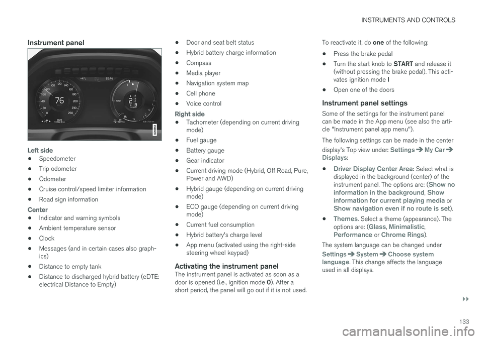
Instrument panel
Left side
•Speedometer
•Trip odometer
•Odometer
•Cruise control/speed limiter information
•Road sign information
Center
•Indicator and warning symbols
•Ambient temperature sensor
•Clock
•Messages (and in certain cases also graph-ics)
•Distance to empty tank
•Distance to discharged hybrid battery (eDTE:electrical Distance to Empty)
•Door and seat belt status
•Hybrid battery charge information
•Compass
•Media player
•Navigation system map
•Cell phone
•Voice control
Right side
•Tachometer (depending on current drivingmode)
•Fuel gauge
•Battery gauge
•Gear indicator
•Current driving mode (Hybrid, Off Road, Pure,Power and AWD)
•Hybrid gauge (depending on current drivingmode)
•ECO gauge (depending on current drivingmode)
•Current fuel consumption
•Hybrid battery's charge level
•App menu (activated using the right-sidesteering wheel keypad)
Activating the instrument panel
The instrument panel is activated as soon as adoor is opened (i.e., ignition mode 0). After ashort period, the panel will go out if it is not used.
To reactivate it, do one of the following:
•Press the brake pedal
•Turn the start knob to START and release it(without pressing the brake pedal). This acti-vates ignition mode I
•Open one of the doors
Instrument panel settings
Some of the settings for the instrument panelcan be made in the App menu (see also the arti-cle "Instrument panel app menu").
The following settings can be made in the center
display's Top view under: SettingsMy CarDisplays:
•Driver Display Center Area: Select what isdisplayed in the background (center) of theinstrument panel. The options are: (Show noinformation in the background, Showinformation for current playing media orShow navigation even if no route is set).
•Themes. Select a theme (appearance). Theoptions are: (Glass, Minimalistic,Performance or Chrome Rings).
The system language can be changed under
SettingsSystemChoose systemlanguage. This change affects the languageused in all displays.
Page 264 of 584
DRIVER SUPPORT
* Option/accessory, for more information, see Introduction.262
Driver support systems
The vehicle is equipped with a number of driversupport systems that help provide the driver withactive/passive support.
Some of these systems are standard while othersare optional and they are designed to e.g., helpthe driver maintain a set speed or a set distanceto a vehicle ahead, or warn the driver of a poten-tial collision situation and in certain cases applythe brakes if necessary. Certain optional systemscan also assist in various parking situations.
Related information
•Adjustable steering force (p. 262)
•Electronic Stability Control (ESC) (p. 263)
•Roll stability control (RSC) (p. 267)
•Speed limiter (SL)* (p. 267)
•Distance Alert* (p. 279)
•Cruise Control (CC) (p. 274)
•Adaptive Cruise Control (ACC)* (p. 281)
•Pilot Assist* (p. 295)
•Driver support system radar sensor (p. 318)
•Driver support system camera (p. 322)
•City Safety™ (p. 326)
•Blind Spot Information (BLIS)* (p. 339)
•Cross Traffic Alert (CTA)* (p. 341)
•Road Sign Information (RSI)* (p. 346)
•Driver Alert Control (DAC) (p. 348)
•Driving lane assistance (p. 350)
•Run-off Mitigation (p. 355)
•Park Assist* (p. 358)
•Park Assist Camera (PAC)* (p. 362)
•Park Assist Pilot (PAP)* (p. 368)
Adjustable steering force
Steering force increases with the speed of thevehicle to give the driver an enhanced sense ofcontrol and stability. At low speed the vehicle iseasier to steer in order to facilitate parking, etc.
Changing the steering force level
To change the level of steering force, see theinformation under the heading "individual" in arti-cle "Drive modes" for additional information.
NOTE
•This steering force level menu functioncannot be accessed when the vehicle isin motion.
•In certain situations, the power steeringfunction may become too hot and mustbe temporarily cooled. During cooling,power steering effect will be reduced andmore force may be necessary to turn thesteering wheel and a message will bedisplayed in the instrument panel.
Related information
•Driver support systems (p. 262)
•Drive modes (p. 420)
Page 269 of 584

DRIVER SUPPORT
}}
* Option/accessory, for more information, see Introduction.267
Roll stability control (RSC)
Volvo's Roll Stability Control (RSC) is a stabilitysystem designed to help minimize the risk of arollover in emergency maneuvers or if a skidshould occur.
RSC uses a gyroscopic sensor that registers theamount of change in the lateral angle at whichthe vehicle is leaning. Using this information, RSCcalculates the likelihood of a rollover. If there isan imminent risk of a rollover, the stability systemis activated, power to the engine is cut and thebrakes are applied to one or more of the wheelsuntil the vehicle regains stability.
WARNING
The vehicle
Page 284 of 584

||
DRIVER SUPPORT
282
vehicle set by the driver. If the radar sensor doesnot detect a vehicle ahead, ACC will insteadmaintain the speed set by the driver.
ACC is designed to smoothly regulate speed.However, the driver must apply the brakes in sit-uations that require immediate braking such aswhen there are great differences in speedbetween vehicles, or if the vehicle ahead brakessuddenly. Due to limitations in the radar sensor,braking may occur unexpectedly or not at all.
Adaptive Cruise Control can follow another vehi-cle from a standstill up to 125 mph (200 km/h).Always observe posted speed limits.
The driver can also toggle between ACC andCruise Control (CC) – see the article "Switchingbetween Cruise Control and Adaptive CruiseControl".
WARNING
•It is advisable to read through all of therelated articles pertaining to ACC (seethe list at the end of this article).
•Adaptive Cruise Control cannot cover alldriving situations and traffic, weather androad conditions.
•This system is designed to be a supple-mentary driving aid. It is not, however,intended to replace the driver's attentionand judgement. The driver is responsiblefor maintaining a safe distance and speedand must intervene if Adaptive CruiseControl does not maintain a suitablespeed or suitable distance to the vehicleahead.
•Maintenance of ACC components mayonly be performed by a trained and quali-fied Volvo technician.
Overview
The distance to the vehicle ahead (in the samelane) is monitored by a radar sensor. Your vehi-cle's speed is regulated by accelerating andbraking. The brakes may emit a sound when theyare being modulated by the adaptive cruise con-trol system. This is normal.
WARNING
•Adaptive Cruise Control is not a collisionavoidance system. The driver is alwaysresponsible for applying the brakes if thesystem does not detect another vehicle.
•Adaptive Cruise Control does not react topeople or animals, or small vehicles suchas bicycles and motorcycles. It also doesnot react to slow moving, parked orapproaching vehicles, or stationaryobjects.
•Do not use Adaptive Cruise Control indemanding driving conditions such as citydriving or other heavy traffic situations, inslippery conditions, when there is a greatdeal of water or slush on the road, duringheavy rain or snow, in poor visibility, onwinding roads or on highway on- or off-ramps.
Page 286 of 584

||
DRIVER SUPPORT
* Option/accessory, for more information, see Introduction.284
WARNING
Adaptive Cruise Control only warns of vehiclesdetected by the radar sensor. In some casesthere may be no warning or the warning maybe delayed. The driver should always apply thebrakes when necessary.
Head-up-display *
A flashing light alerts the driver
A flashing icon will appear in the head-up displayto alert the driver of a collision risk.
NOTE
Strong sunlight, reflections, extreme light con-trasts, the use of sunglasses, or if the driver isnot looking straight ahead may make the vis-ual warning signal in the windshield difficult tosee.
Related information
•Starting and activating Adaptive CruiseControl (ACC)* (p. 284)
•Changing Adaptive Cruise Control (ACC)speed (p. 287)
•Setting an Adaptive Cruise Control timeinterval (p. 288)
•Changing target vehicles and automaticbraking with Adaptive Cruise Control (ACC)(p. 289)
•Switching between Cruise Control andAdaptive Cruise Control* (p. 278)
•Passing Assistance with Adaptive CruiseControl or Pilot Assist-2 (p. 289)
•Deactivating/resuming Adaptive CruiseControl (ACC) (p. 285)
•Adaptive Cruise Control (ACC) - trouble-shooting (p. 291)
•Adaptive Cruise Control (ACC) symbols andmessages (p. 293)
•Pilot Assist* (p. 295)
•Distance Alert* (p. 279)
•Head-up display (HUD)* (p. 122)
•Radar sensor limitations (p. 319)
Starting and activating Adaptive
Cruise Control (ACC)*
ACC must first be put in active mode before itcan be started in order to regulate speed or aset time interval to the vehicle ahead.
Starting ACC (putting it in standby
mode)
Function buttons and symbols
–Press ◀ (2) or ▶ (3) to scroll to the ACC
() function. The symbol (4) will be dis-played in the instrument panel.
>The symbol indicates that ACC has beenstarted and is in standby mode. Instandby mode, the vehicle will not main-tain a set speed or a time interval to thevehicle ahead.
Page 288 of 584
||
DRIVER SUPPORT
* Option/accessory, for more information, see Introduction.286
WARNING
When ACC is in standby mode, the driver hasto control the vehicle's speed and distance toa vehicle ahead.
When ACC is in standby mode, the driver willbe alerted if the distance to the vehicle aheadis too short by the Distance Alert function.See the article "Distance Alert" for additionalinformation.
Standby mode due to action by the driver
ACC is temporarily deactivated and put instandby mode if:
•the brakes are applied
•The gear selector is moved to N
•the vehicle is driven faster than the setspeed for more than 1 minute.
In these cases, the driver will have to regulate thevehicle's speed.
A temporary increase in speed, such as whenpassing another vehicle, does not affect the ACCset speed. The vehicle will return to the set speedwhen the accelerator pedal is released.
Automatic standby mode
ACC interacts with other systems, such asElectronic Stability Control. If any of these othersystems are not functioning properly, ACC willturn off automatically.
WARNING
If this happens, the driver will be alerted by anaudible signal and a message in the instru-ment panel. The driver will have to adapt thevehicle's speed, apply the brakes when nec-essary and keep a safe distance to the vehicleahead.
ACC switches automatically to standby mode if:
•the vehicle's speed goes below approx.3 mph (5 km/h) and ACC cannot determineif the vehicle ahead is stationary or is anobject such as a speed bump, etc
•the vehicle's speed goes below approx.3 mph (5 km/h) and the vehicle aheadchanges lanes or turns so that ACC nolonger has a target vehicle to follow
•the driver opens the door
•the driver unbuckles the seat belt
•the engine speed (rpm) is too high/low
•the wheels lose traction
•the brake temperature is too high
•the parking brake is applied
•the stability system's ESC Sport Mode isactivated
•the Off Road drive mode is selected
•The radar sensor is covered by e.g., wet snowor if heavy rain interferes with radar waves
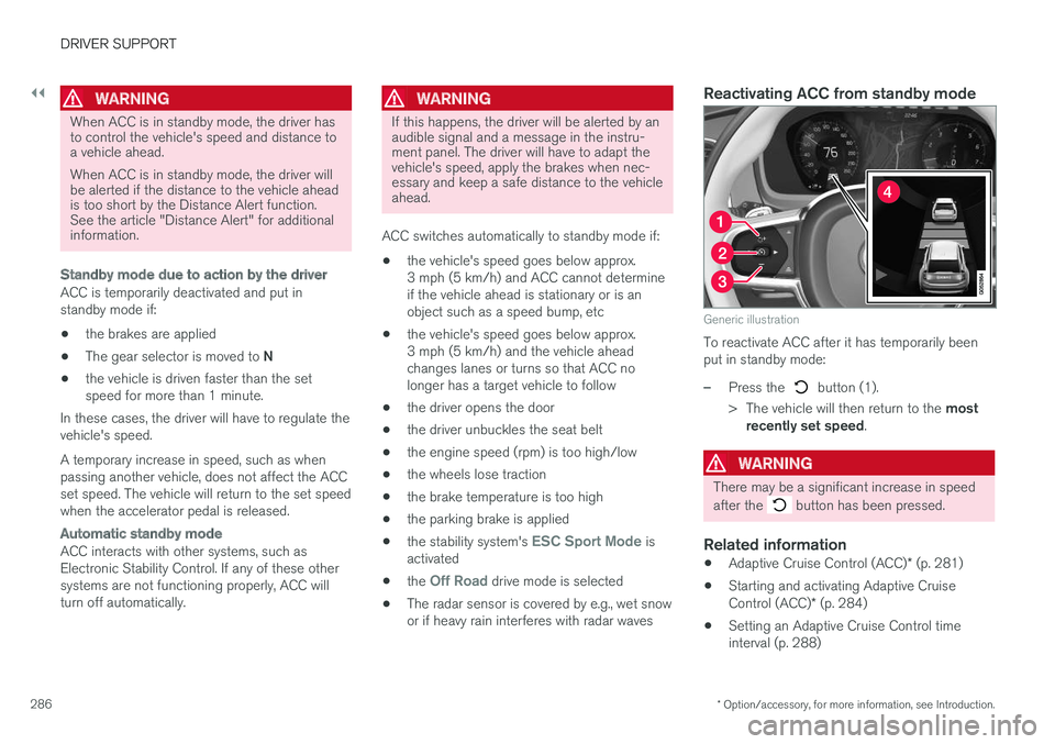
Reactivating ACC from standby mode
Generic illustration
To reactivate ACC after it has temporarily beenput in standby mode:
–Press the button (1).
>The vehicle will then return to the mostrecently set speed.
WARNING
There may be a significant increase in speed
after the button has been pressed.
Related information
•Adaptive Cruise Control (ACC)* (p. 281)
•Starting and activating Adaptive CruiseControl (ACC)* (p. 284)
•Setting an Adaptive Cruise Control timeinterval (p. 288)
Page 294 of 584
DRIVER SUPPORT
* Option/accessory, for more information, see Introduction.292
Adaptive Cruise Control (ACC) -limitations
Adaptive Cruise Control (ACC) functionality maybe limited in certain situations.
Steep roads and/or heavy loads
Adaptive Cruise Control is primarily intended foruse on relatively level roads. The function may notbe able to maintain the correct time interval tothe vehicle ahead when driving down steep hills.The driver should be attentive and prepared toapply the brakes in these situations.
Do not use Adaptive Cruise Control when thevehicle is transporting a heavy load or if it is tow-ing a trailer.
Additional information
•The Off Road drive mode cannot beselected if Adaptive Cruise Control is acti-vated.
•Adaptive Cruise Control uses the vehicle'scamera and radar sensor, which have certaingeneral limitations. See the articles "Cameralimitations" and "Radar sensor limitations"for additional information.
Related information
•Adaptive Cruise Control (ACC)* (p. 281)
•Radar sensor limitations (p. 319)
•Camera limitations (p. 323)