ESP YAMAHA DT125R 2000 Owners Manual
[x] Cancel search | Manufacturer: YAMAHA, Model Year: 2000, Model line: DT125R, Model: YAMAHA DT125R 2000Pages: 91, PDF Size: 4.67 MB
Page 27 of 91
3-14
INSTRUMENT AND CONTROL FUNCTIONS
1
23
4
5
6
7
8
9
12
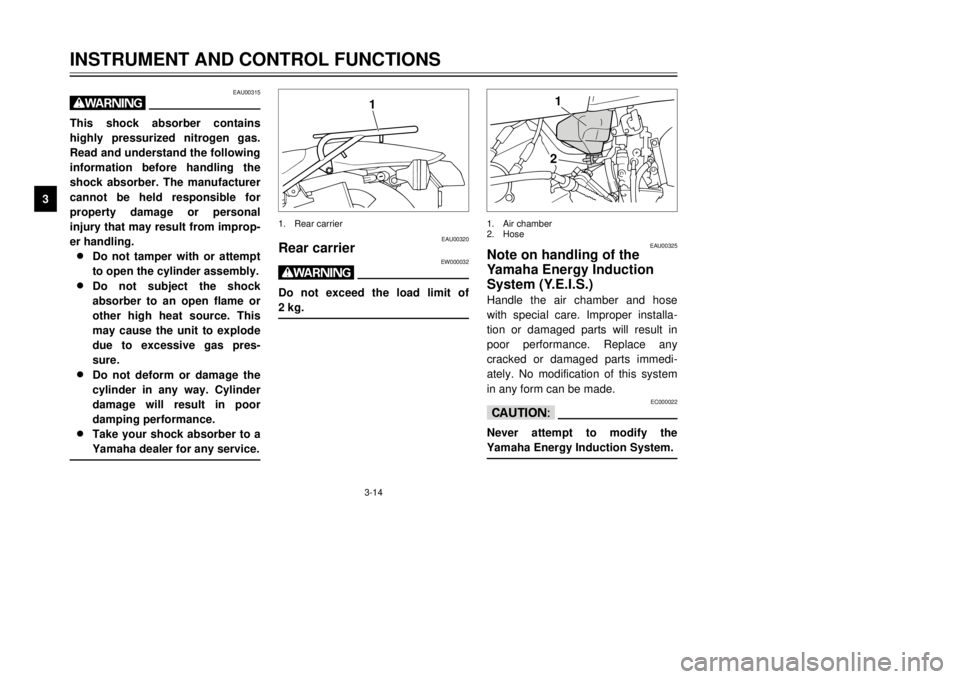
1.Air chamber
2.Hose
EAU00325
Note on handling of the
Yamaha Energy Induction
System (Y.E.I.S.)Handle the air chamber and hose
with special care. Improper installa-
tion or damaged parts will result in
poor performance. Replace any
cracked or damaged parts immedi-
ately. No modification of this system
in any form can be made.
EC000022
cCNever attempt to modify the
Yamaha Energy Induction System.
EAU00315
wThis shock absorber contains
highly pressurized nitrogen gas.
Read and understand the following
information before handling the
shock absorber. The manufacturer
cannot be held responsible for
property damage or personal
injury that may result from improp-
er handling.
8 8
Do not tamper with or attempt
to open the cylinder assembly.
8 8
Do not subject the shock
absorber to an open flame or
other high heat source. This
may cause the unit to explode
due to excessive gas pres-
sure.
8 8
Do not deform or damage the
cylinder in any way. Cylinder
damage will result in poor
damping performance.
8 8
Take your shock absorber to a
Yamaha dealer for any service.
1
EAU00320
Rear carrier
EW000032
wDo not exceed the load limit of
2 kg.1.Rear carrier
3MB-9-E7 12/27/00 2:52 PM Page 26
Page 29 of 91
EW000045
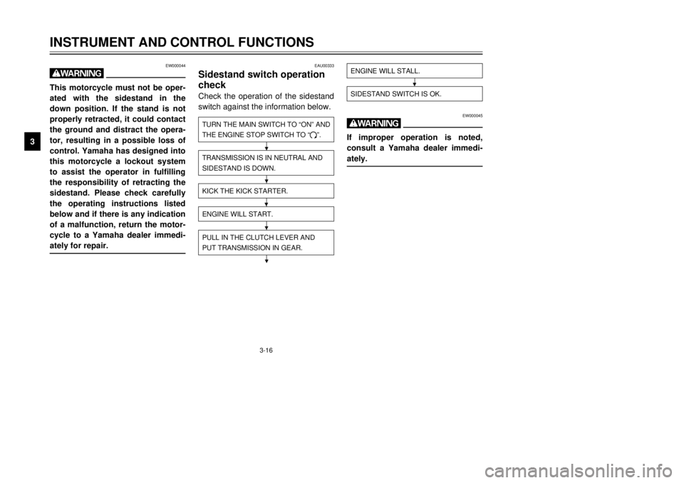
wIf improper operation is noted,
consult a Yamaha dealer immedi-
ately.
3-16
INSTRUMENT AND CONTROL FUNCTIONS
1
23
4
5
6
7
8
9
ENGINE WILL STALL.SIDESTAND SWITCH IS OK.
EAU00333
Sidestand switch operation
checkCheck the operation of the sidestand
switch against the information below.TURN THE MAIN SWITCH TO ÒONÓ AND
THE ENGINE STOP SWITCH TO Ò#Ó.TRANSMISSION IS IN NEUTRAL AND
SIDESTAND IS DOWN.PULL IN THE CLUTCH LEVER AND
PUT TRANSMISSION IN GEAR.ENGINE WILL START.KICK THE KICK STARTER.
EW000044
wThis motorcycle must not be oper-
ated with the sidestand in the
down position. If the stand is not
properly retracted, it could contact
the ground and distract the opera-
tor, resulting in a possible loss of
control. Yamaha has designed into
this motorcycle a lockout system
to assist the operator in fulfilling
the responsibility of retracting the
sidestand. Please check carefully
the operating instructions listed
below and if there is any indication
of a malfunction, return the motor-
cycle to a Yamaha dealer immedi-
ately for repair.
3MB-9-E7 12/27/00 2:52 PM Page 28
Page 30 of 91

4-1
EAU01114
PRE-OPERATION CHECKS
1
2
34
5
6
7
8
9 Owners are personally responsible for their vehicleÕs condition. Your motorcycleÕs vital functions can start to deteriorate
quickly and unexpectedly, even if it remains unused (for instance, if it is exposed to the elements). Any damage, fluid
leak or loss of tire pressure could have serious consequences. Therefore, it is very important that, in addition to a thor-
ough visual inspection, you check the following points before each ride.
EAU00340
PRE-OPERATION CHECK LIST
ITEMCHECKSPAGE
Front brake9Check operation, free play, fluid level and vehicle for fluid leakage.
9Fill with DOT 4 (or DOT 3) brake fluid if necessary.
3-6, 6-21 ~ 6-25
Rear brake9Check operation, free play, fluid level and vehicle for fluid leakage.
9Fill with DOT 4 (or DOT 3) brake fluid if necessary.
Clutch9Check operation, condition and free play.
3-5, 6-21
9Adjust if necessary.
9Check for smooth operation.
Throttle grip and housing9Lubricate.6-17, 6-27
9Adjust throttle cable free play if necessary.
Engine oil9Check oil level.
3-9
9Fill with oil if necessary.
Transmission oil9Check oil level.
6-11 ~ 6-12
9Fill with oil if necessary.
Coolant9Check coolant level.
6-12
9Fill with coolant if necessary.
Drive chain9Check chain slack and condition.
6-26 ~ 6-27
9Adjust if necessary.
Wheels and tires9Check tire pressure, wear, damage and spoke tightness.
6-18 ~ 6-20
9Tighten spokes if necessary.
Control and meter cable9Check for smooth operation.
6-27
9Lubricate if necessary.
3MB-9-E7 12/27/00 2:52 PM Page 29
Page 34 of 91
5-3
OPERATION AND IMPORTANT RIDING POINTS
1
2
3
45
6
7
8
9 1.Turn the fuel cock to ÒONÓ.
2.Turn the main switch to ÒONÓ and
the engine stop switch to Ò#Ó.
3.Shift the transmission into neu-
tral.
NOTE:
When the transmission is in neutral,
the neutral indicator light should be
on. If the light does not come on, ask
a Yamaha dealer to inspect it.4.Turn on the starter (choke) and
completely close the throttle grip.
5.Kick the kick starter to start the
engine.
6.After starting the engine, move
the starter (choke) to the halfway
position.
NOTE:
For maximum engine life, never
accelerate hard with a cold engine!7.After the engine is warm, turn off
the starter (choke) completely.NOTE:
The engine is warm when it responds
normally to the throttle with the starter
(choke) turned off.
EAU01258
Starting a warm engineThe starter (choke) is not required
when the engine is warm.
EC000046
cCSee the ÒEngine break-inÓ section
prior to operating the motorcycle
for the first time.
3MB-9-E7 12/27/00 2:52 PM Page 33
Page 54 of 91
6-17
PERIODIC MAINTENANCE AND MINOR REPAIR
1
2
3
4
56
7
8
9
b
a
1
EAU00632
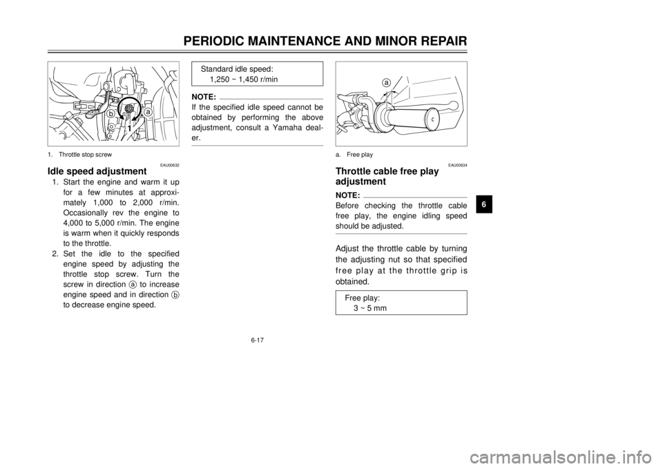
Idle speed adjustment1.Start the engine and warm it up
for a few minutes at approxi-
mately 1,000 to 2,000 r/min.
Occasionally rev the engine to
4,000 to 5,000 r/min. The engine
is warm when it quickly responds
to the throttle.
2.Set the idle to the specified
engine speed by adjusting the
throttle stop screw. Turn the
screw in direction ato increase
engine speed and in direction b
to decrease engine speed.1.Throttle stop screw
NOTE:
If the specified idle speed cannot be
obtained by performing the above
adjustment, consult a Yamaha deal-
er.
Standard idle speed:
1,250 ~ 1,450 r/min
a
EAU00634
Throttle cable free play
adjustmentNOTE:
Before checking the throttle cable
free play, the engine idling speed
should be adjusted.Adjust the throttle cable by turning
the adjusting nut so that specified
free play at the throttle grip is
obtained.a.Free play
Free play:
3 ~ 5 mm
3MB-9-E7 12/27/00 2:52 PM Page 53
Page 63 of 91
6-26
PERIODIC MAINTENANCE AND MINOR REPAIR
1
2
3
4
56
7
8
9
EC000096
cCToo little chain slack will overload
the engine and other vital parts.
Keep the slack within the specified
limits.3.Tighten the wheel axle nut to the
specified torque.
EAU01533*
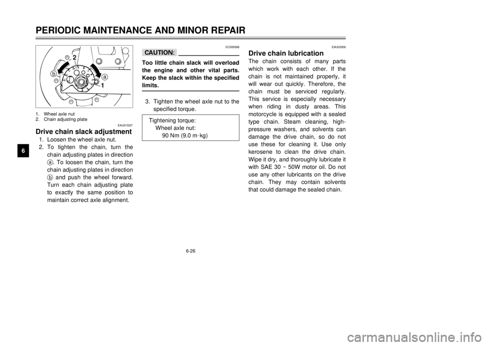
Drive chain slack adjustment1.Loosen the wheel axle nut.
2.To tighten the chain, turn the
chain adjusting plates in direction
a. To loosen the chain, turn the
chain adjusting plates in direction
band push the wheel forward.
Turn each chain adjusting plate
to exactly the same position to
maintain correct axle alignment.
a b
2
1
1.Wheel axle nut
2.Chain adjusting plate
Tightening torque:
Wheel axle nut:
90 Nm (9.0 m
0kg)
EAU03006
Drive chain lubricationThe chain consists of many parts
which work with each other. If the
chain is not maintained properly, it
will wear out quickly. Therefore, the
chain must be serviced regularly.
This service is especially necessary
when riding in dusty areas. This
motorcycle is equipped with a sealed
type chain. Steam cleaning, high-
pressure washers, and solvents can
damage the drive chain, so do not
use these for cleaning it. Use only
kerosene to clean the drive chain.
Wipe it dry, and thoroughly lubricate it
with SAE 30 ~ 50W motor oil. Do not
use any other lubricants on the drive
chain. They may contain solvents
that could damage the sealed chain.
3MB-9-E7 12/27/00 2:52 PM Page 62
Page 79 of 91
7-1
EAU01518
MOTORCYCLE CARE AND STORAGE
1
2
3
4
5
67
8
9
CareThe exposure of its technology
makes a motorcycle charming but
also vulnerable. Although high-quality
components are used, they are not
all rust-resistant. While a rusty
exhaust pipe may remain unnoticed
on a car, it does look unattractive on
a motorcycle. Frequent and proper
care, however, will keep your motor-
cycle looking good, extend its life and
maintain its performance. Moreover,
the warranty states that the vehicle
must be properly taken care of. For
all these reasons, it is recommended
that you observe the following clean-
ing and storing precautions.Before cleaning
1.Cover up the muffler outlet with a
plastic bag.
2.Make sure that all caps and cov-
ers as well as all electrical cou-
plers and connectors, including
the spark plug cap, are tightly
installed.
3.Remove extremely stubborn dirt,
like oil burnt onto the crankcase,
with a degreasing agent and a
brush, but never apply such
products onto seals, gaskets,
sprockets, the drive chain and
wheel axles. Always rinse the dirt
and degreaser off with water.Cleaning
After normal use
Remove dirt with warm water, a neu-
tral detergent and a soft clean
sponge, then rinse with plenty of
clean water. Use a tooth or bottle
brush for hard-to-reach parts.
Tougher dirt and insects will come off
more easily if the area is covered with
a wet cloth for a few minutes before
cleaning.
ECA00010
cC8
8
Avoid using strong acidic
wheel cleaners, especially on
spoked wheels. If you do use
such products for hard-to-
remove dirt, do not leave it on
any longer than instructed,
then thoroughly rinse it off
with water, immediately dry
the area and apply a corrosion
protection spray.
3MB-9-E7 12/27/00 2:52 PM Page 78
Page 86 of 91

8-3
1
2
3
4
5
6
78
9
SPECIFICATIONS
90 kg load ~ maximum
load*
Front150 kPa (1.50 kg/cm
2, 1.50 bar)
Rear175 kPa (1.75 kg/cm2, 1.75 bar)
Off-road riding
Front125 kPa (1.25 kg/cm2, 1.25 bar)
Rear150 kPa (1.50 kg/cm2, 1.50 bar)
* Load is total weight of cargo, rider, passenger and accessories.
Wheels
Front
TypeSpoke wheel
Size1.60 ´21
Rear
TypeSpoke wheel
Size1.85 ´18
Brakes
Front
TypeSingle disc brake
OperationRight hand operation
FluidDOT 3 or DOT 4Rear
TypeSingle disc brake
OperationRight foot operation
FluidDOT 3 or DOT 4
Suspension
FrontTelescopic fork
RearSwingarm (link suspension)
Shock absorber
FrontCoil spring/oil damper
RearCoil-gas spring/oil damper
Wheel travel
Front270 mm
Rear260 mm
Electrical
Ignition systemC.D.I.
Charging system
TypeC.D.I. magneto
3MB-9-E7 12/27/00 2:52 PM Page 85