check engine YAMAHA DT125R 2000 Owners Manual
[x] Cancel search | Manufacturer: YAMAHA, Model Year: 2000, Model line: DT125R, Model: YAMAHA DT125R 2000Pages: 91, PDF Size: 4.67 MB
Page 6 of 91
EAU00009
TABLE OF CONTENTS
1
2
3
4
5
6
7
8
9 GIVE SAFETY THE RIGHT OF WAY..................1-1
DESCRIPTION....................................................2-1
Left view............................................................2-1
Right view.........................................................2-2
Controls/Instruments.........................................2-3
INSTRUMENT AND CONTROL FUNCTIONS....3-1
Main switch.......................................................3-1
Indicator lights...................................................3-1
Oil level indicator circuit check..........................3-2
Speedometer....................................................3-3
Tachometer.......................................................3-3
Engine temperature gauge...............................3-4
Handlebar switches..........................................3-4
Clutch lever.......................................................3-5
Shift pedal.........................................................3-5
Front brake lever...............................................3-6
Rear brake pedal..............................................3-6
Fuel tank cap....................................................3-6
Fuel (except for Switzerland and Austria).........3-7
Fuel (for Switzerland and Austria)....................3-7
Catalyzer (for Switzerland and Austria)............3-8
Two-stroke engine oil........................................3-9
Fuel cock..........................................................3-9
Starter (choke) Ò
1Ó.........................................3-10Kick starter......................................................3-11
Steering lock...................................................3-11
Seat................................................................3-12
Helmet holder.................................................3-12
Rear shock absorber adjustment....................3-13
Rear carrier.....................................................3-14
Note on handling of the Yamaha Energy
Induction System (Y.E.I.S.).............................3-14
Y.P.V.S.
(Yamaha Power Valve System)......................3-15
Sidestand........................................................3-15
Sidestand switch operation check..................3-16
PRE-OPERATION CHECKS...............................4-1
Pre-operation check list....................................4-1
OPERATION AND IMPORTANT RIDING
POINTS................................................................5-1
Starting the engine............................................5-1
Starting a warm engine.....................................5-3
Shifting..............................................................5-4
Recommended shift points
(for Switzerland only)........................................5-4
Tips for reducing fuel consumption...................5-5
Engine break-in.................................................5-5
Parking..............................................................5-6
123
45
3MB-9-E7 12/27/00 2:52 PM Page 5
Page 14 of 91
3-1
ON
OFF
EAU00028
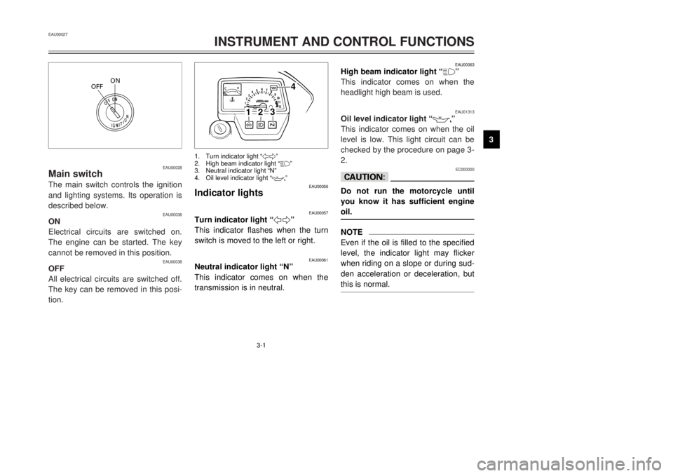
Main switchThe main switch controls the ignition
and lighting systems. Its operation is
described below.
EAU00036
ON
Electrical circuits are switched on.
The engine can be started. The key
cannot be removed in this position.
EAU00038
OFF
All electrical circuits are switched off.
The key can be removed in this posi-
tion.EAU00027
INSTRUMENT AND CONTROL FUNCTIONS
1
23
4
5
6
7
8
9
EAU00063
High beam indicator light Ò
&Ó
This indicator comes on when the
headlight high beam is used.
EAU01313
Oil level indicator light Ò
7
Ó
This indicator comes on when the oil
level is low. This light circuit can be
checked by the procedure on page 3-
2.EC000000
cCDo not run the motorcycle until
you know it has sufficient engine
oil.NOTE
Even if the oil is filled to the specified
level, the indicator light may flicker
when riding on a slope or during sud-
den acceleration or deceleration, but
this is normal.
1
2
3
4
EAU00056
Indicator lights
EAU00057
Turn indicator light Ò5Ó
This indicator flashes when the turn
switch is moved to the left or right.
EAU00061
Neutral indicator light ÒNÓ
This indicator comes on when the
transmission is in neutral.1.Turn indicator light Ò5Ó
2.High beam indicator light Ò&Ó
3.Neutral indicator light ÒNÓ
4.Oil level indicator light Ò
7
Ó
3MB-9-E7 12/27/00 2:52 PM Page 13
Page 15 of 91
EAU00075
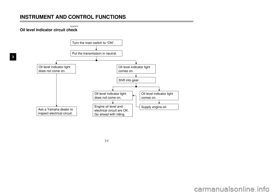
Oil level indicator circuit check
3-2
INSTRUMENT AND CONTROL FUNCTIONS
1
23
4
5
6
7
8
9Turn the main switch to ÒONÓ.
Put the transmission in neutral.
Oil level indicator light
does not come on.Ask a Yamaha dealer to
inspect electrical circuit.
Oil level indicator light
comes on.
Oil level indicator light
does not come on.
Supply engine oil.
Shift into gear.
Engine oil level and
electrical circuit are OK.
Go ahead with riding.
Oil level indicator light
comes on.
3MB-9-E7 12/27/00 2:52 PM Page 14
Page 24 of 91
3-11
INSTRUMENT AND CONTROL FUNCTIONS
1
23
4
5
6
7
8
9
1
EAU00212
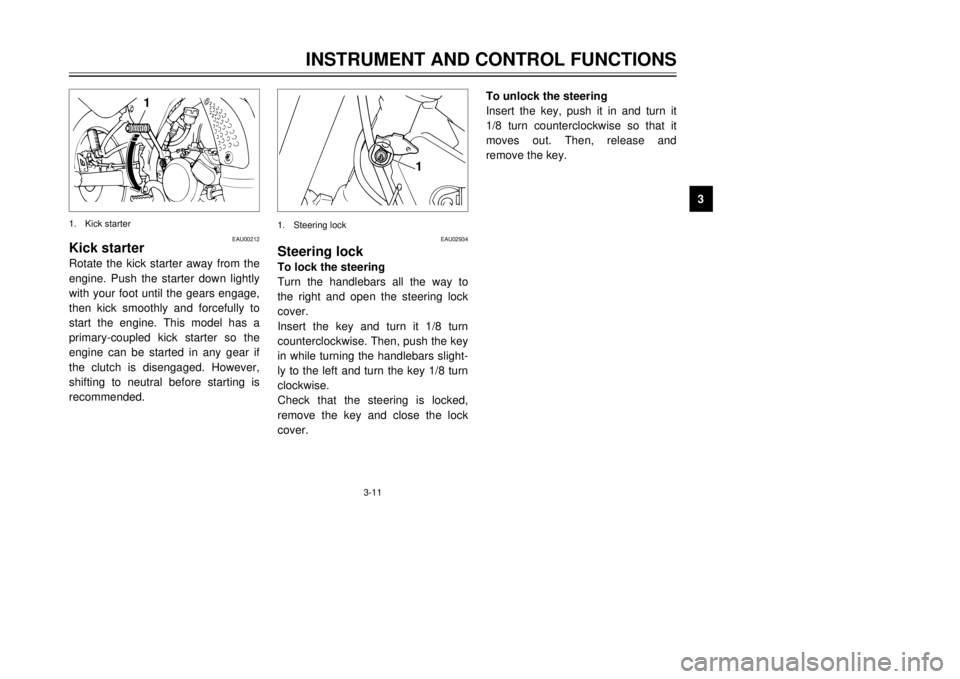
Kick starterRotate the kick starter away from the
engine. Push the starter down lightly
with your foot until the gears engage,
then kick smoothly and forcefully to
start the engine. This model has a
primary-coupled kick starter so the
engine can be started in any gear if
the clutch is disengaged. However,
shifting to neutral before starting is
recommended.1.Kick starter
EAU02934
Steering lockTo lock the steering
Turn the handlebars all the way to
the right and open the steering lock
cover.
Insert the key and turn it 1/8 turn
counterclockwise. Then, push the key
in while turning the handlebars slight-
ly to the left and turn the key 1/8 turn
clockwise.
Check that the steering is locked,
remove the key and close the lock
cover.
1
1.Steering lock
To unlock the steering
Insert the key, push it in and turn it
1/8 turn counterclockwise so that it
moves out. Then, release and
remove the key.
3MB-9-E7 12/27/00 2:52 PM Page 23
Page 29 of 91
EW000045
wIf improper operation is noted,
consult a Yamaha dealer immedi-
ately.
3-16
INSTRUMENT AND CONTROL FUNCTIONS
1
23
4
5
6
7
8
9
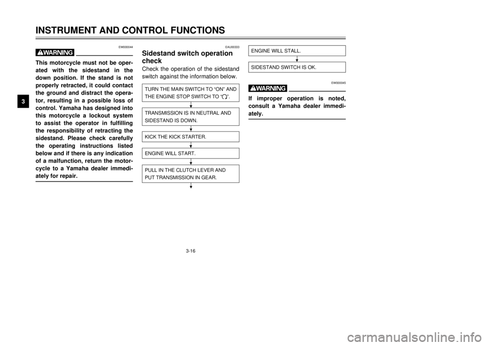
ENGINE WILL STALL.SIDESTAND SWITCH IS OK.
EAU00333
Sidestand switch operation
checkCheck the operation of the sidestand
switch against the information below.TURN THE MAIN SWITCH TO ÒONÓ AND
THE ENGINE STOP SWITCH TO Ò#Ó.TRANSMISSION IS IN NEUTRAL AND
SIDESTAND IS DOWN.PULL IN THE CLUTCH LEVER AND
PUT TRANSMISSION IN GEAR.ENGINE WILL START.KICK THE KICK STARTER.
EW000044
wThis motorcycle must not be oper-
ated with the sidestand in the
down position. If the stand is not
properly retracted, it could contact
the ground and distract the opera-
tor, resulting in a possible loss of
control. Yamaha has designed into
this motorcycle a lockout system
to assist the operator in fulfilling
the responsibility of retracting the
sidestand. Please check carefully
the operating instructions listed
below and if there is any indication
of a malfunction, return the motor-
cycle to a Yamaha dealer immedi-
ately for repair.
3MB-9-E7 12/27/00 2:52 PM Page 28
Page 30 of 91

4-1
EAU01114
PRE-OPERATION CHECKS
1
2
34
5
6
7
8
9 Owners are personally responsible for their vehicleÕs condition. Your motorcycleÕs vital functions can start to deteriorate
quickly and unexpectedly, even if it remains unused (for instance, if it is exposed to the elements). Any damage, fluid
leak or loss of tire pressure could have serious consequences. Therefore, it is very important that, in addition to a thor-
ough visual inspection, you check the following points before each ride.
EAU00340
PRE-OPERATION CHECK LIST
ITEMCHECKSPAGE
Front brake9Check operation, free play, fluid level and vehicle for fluid leakage.
9Fill with DOT 4 (or DOT 3) brake fluid if necessary.
3-6, 6-21 ~ 6-25
Rear brake9Check operation, free play, fluid level and vehicle for fluid leakage.
9Fill with DOT 4 (or DOT 3) brake fluid if necessary.
Clutch9Check operation, condition and free play.
3-5, 6-21
9Adjust if necessary.
9Check for smooth operation.
Throttle grip and housing9Lubricate.6-17, 6-27
9Adjust throttle cable free play if necessary.
Engine oil9Check oil level.
3-9
9Fill with oil if necessary.
Transmission oil9Check oil level.
6-11 ~ 6-12
9Fill with oil if necessary.
Coolant9Check coolant level.
6-12
9Fill with coolant if necessary.
Drive chain9Check chain slack and condition.
6-26 ~ 6-27
9Adjust if necessary.
Wheels and tires9Check tire pressure, wear, damage and spoke tightness.
6-18 ~ 6-20
9Tighten spokes if necessary.
Control and meter cable9Check for smooth operation.
6-27
9Lubricate if necessary.
3MB-9-E7 12/27/00 2:52 PM Page 29
Page 32 of 91

5-1
1
2
3
45
6
7
8
9
EAU00373
w8 8
Before riding this motorcycle,
become thoroughly familiar
with all operating controls and
their functions. Consult a
Yamaha dealer regarding any
control or function that you do
not thoroughly understand.
8 8
Never start your engine or let
it run for any length of time in
a closed area. The exhaust
fumes are poisonous and can
cause loss of consciousness
and death within a short time.
Always operate your motorcy-
cle in an area with adequate
ventilation.
8 8
Before starting out, always be
sure the sidestand is up.
Failure to retract the sidestand
completely can result in a seri-
ous accident when you try to
turn a corner.
EAU01177
Starting the engineNOTE:
This motorcycle is equipped with an
ignition circuit cut-off system. The
engine can be started only under one
of the following conditions:
8The transmission is in neutral.
8The sidestand is up, the trans-
mission is in gear and the clutch
is disengaged.
The motorcycle must not be ridden
when the sidestand is down.
EW000056
wBefore going through the following
steps, check the function of the
sidestand switch. (Refer to page
3-16.)
EAU00372
OPERATION AND IMPORTANT RIDING POINTS
3MB-9-E7 12/27/00 2:52 PM Page 31
Page 42 of 91

6-5
PERIODIC MAINTENANCE AND MINOR REPAIR
1
2
3
4
56
7
8
9
EAU03884
NOTE:
8The air filter needs more frequent service if you are riding in unusually wet or dusty areas.
8Hydraulic brake service
9Regularly check and, if necessary, correct the brake fluid level.
9Every two years replace the internal components of the brake master cylinders and calipers, and change the
brake fluid.
9Replace the brake hoses every four years and if cracked or damaged.21
*Carburetor¥Check starter (choke) operation.
¥Adjust engine idling speed.ÖÖÖÖÖÖ
22*Autolube pump¥Check operation.
¥Bleed if necessary.ÖÖÖÖ
23Transmission oil¥Check oil level.ÖÖÖÖÖÖ
¥Change.ÖÖ
24*Cooling system¥Check coolant level and vehicle for coolant leakage.ÖÖÖÖÖ
¥Change.Every 3 years
25*Front and rear brake
switches¥Check operation.ÖÖÖÖÖÖ
26Moving parts and cables¥Lubricate.ÖÖÖÖÖ
27*Lights, signals and
switches¥Check operation.
¥Adjust headlight beam.ÖÖÖÖÖÖ NO.ITEMCHECK OR MAINTENANCE JOBODOMETER READING (´ 1,000 km)
ANNUAL
CHECK
16121824
3MB-9-E7 12/27/00 2:52 PM Page 41
Page 48 of 91
6-11
PERIODIC MAINTENANCE AND MINOR REPAIR
1
2
3
4
56
7
8
9 Spark plug gap:
0.7 ~ 0.8 mm
Tightening torque:
Spark plug:
20 Nm (2.0 m
0kg)
1
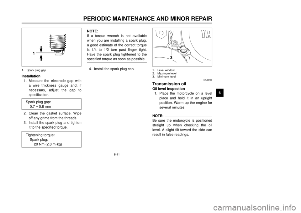
3 2
EAU03109
Transmission oilOil level inspection
1.Place the motorcycle on a level
place and hold it in an upright
position. Warm up the engine for
several minutes.NOTE:
Be sure the motorcycle is positioned
straight up when checking the oil
level. A slight tilt toward the side can
result in false readings.1.Level window
2.Maximum level
3.Minimum level
Installation
1.Measure the electrode gap with
a wire thickness gauge and, if
necessary, adjust the gap to
specification.
2.Clean the gasket surface. Wipe
off any grime from the threads.
3.Install the spark plug and tighten
it to the specified torque.
1
1.Spark plug gap
NOTE:
If a torque wrench is not available
when you are installing a spark plug,
a good estimate of the correct torque
is 1/4 to 1/2 turn past finger tight.
Have the spark plug tightened to the
specified torque as soon as possible.4.Install the spark plug cap.
3MB-9-E7 12/27/00 2:52 PM Page 47
Page 49 of 91
6-12
PERIODIC MAINTENANCE AND MINOR REPAIR
1
2
3
4
56
7
8
95.Fill the engine with sufficient oil
to reach the specified level.
Install the oil filler cap and tight-
en it.
EC000079
cCDo not put in any chemical addi-
tives. Transmission oil also lubri-
cates the clutch and additives
could cause clutch slippage.6.Start the engine and warm up for
a few minutes. While warming
up, check for oil leakage. If oil
leakage is found, stop the engine
immediately and check for
cause. Recommended oil:
See page 8-1.
Oil quantity:
Total amount: 0.8 L
Periodic oil change: 0.75 L
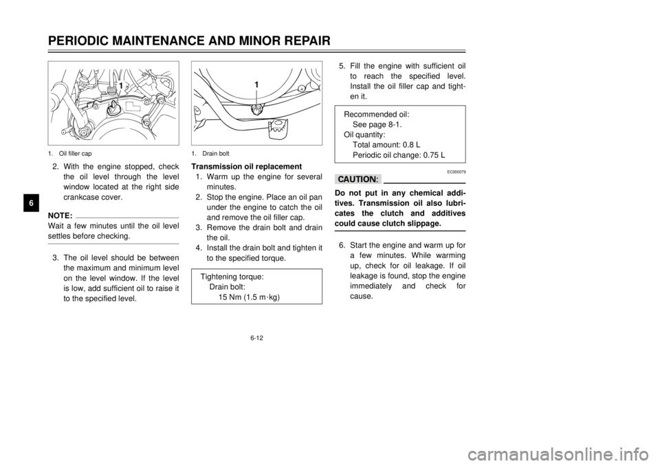
1
Transmission oil replacement
1.Warm up the engine for several
minutes.
2.Stop the engine. Place an oil pan
under the engine to catch the oil
and remove the oil filler cap.
3.Remove the drain bolt and drain
the oil.
4.Install the drain bolt and tighten it
to the specified torque.1.Drain bolt
Tightening torque:
Drain bolt:
15 Nm (1.5 m
0kg)
1
2.With the engine stopped, check
the oil level through the level
window located at the right side
crankcase cover.NOTE:
Wait a few minutes until the oil level
settles before checking.3.The oil level should be between
the maximum and minimum level
on the level window. If the level
is low, add sufficient oil to raise it
to the specified level.1.Oil filler cap
3MB-9-E7 12/27/00 2:52 PM Page 48